The beating heart of any automobile, the engine bay, is a marvel of engineering, a complex symphony of metal, plastic, rubber, and fluids meticulously designed for performance. For 3D artists, game developers, and automotive visualization specialists, recreating this intricate space in stunning digital realism presents one of the most rewarding yet challenging tasks. A truly convincing 3D car model isn’t just about a polished exterior; it’s about the depth, detail, and functional accuracy that extends beneath the hood. The ability to model, texture, and render an engine bay with photorealistic precision can elevate a project from good to exceptional, captivating audiences with its authenticity and technical prowess.
This comprehensive guide delves into the advanced techniques and industry best practices required to craft hyper-realistic 3D engine bay models. We’ll explore everything from foundational topology strategies and meticulous UV mapping to advanced PBR material creation, high-fidelity rendering workflows, and crucial optimization techniques for real-time applications like game engines and AR/VR. Whether you’re aiming for a cinematic render, an interactive automotive configurator, or a high-performance game asset, mastering the art of the 3D engine bay is paramount. Prepare to unlock the secrets to transforming complex mechanical references into breathtaking digital art.
Mastering Engine Bay Topology and Modeling Precision
The foundation of any realistic 3D model, especially one as intricate as an engine bay, lies in its topology. Clean, efficient, and well-structured geometry is not merely an aesthetic choice; it dictates how well a model will deform, how easily it can be UV mapped, and ultimately, how accurately it will render and perform in real-time environments. For engine bay components, which are a mix of hard surfaces, organic shapes (hoses), and numerous small details, precision is paramount.
The Foundation: Blueprint Analysis and Reference Gathering
Before touching any modeling tools, the most critical step is comprehensive reference gathering. This involves more than just a few online images. Seek out:
- Technical Schematics and Blueprints: These provide accurate dimensions, proportions, and placement of components.
- High-Resolution Photographs: Capture details from multiple angles, focusing on material finishes, wear, and specific connections. Look for detailed shots of bolts, clamps, labels, and wiring harnesses.
- Real-World Inspections: If possible, examining a physical engine bay provides invaluable insight into how components fit together, cable routing, and the nuances of various material interactions under different lighting conditions.
Organize your references meticulously. A well-categorized reference library will save countless hours of guesswork and ensure anatomical correctness, which is crucial for believability.
Strategic Subdivision and Edge Flow for Complex Components
Engine bay modeling primarily involves hard-surface techniques. The goal is to achieve crisp edges and smooth curves without excessive polygon counts. Here’s how:
- Base Mesh Creation: Start with simple primitives (cubes, cylinders) and gradually refine them. Use blocking out to establish the main forms and proportions of major components like the engine block, cylinder heads, and intake manifold.
- Edge Loops and Support Edges: To maintain sharp edges when subdividing (e.g., using a Subdivision Surface modifier in Blender or Turbosmooth in 3ds Max), strategically place ‘support loops’ close to the hard edges. These extra edges prevent the mesh from smoothing out too much, preserving the intended sharpness.
- N-gons and Triangles: While modern renderers and game engines handle triangles well, maintaining an all-quad topology is generally preferred during the modeling phase. Quads offer better control over edge flow, cleaner subdivisions, and easier UV unwrapping. Convert to triangles only as a final step for game engine export if necessary.
- Hoses and Wires: Model these using spline-based workflows, then convert to mesh. Ensure a consistent number of divisions along their length for smooth curvature. The Blender 4.4 documentation provides excellent guidance on using curves and modifiers for creating precise cylindrical objects.
- Small Details (Bolts, Clips, Labels): For extreme close-ups, these should be modeled. For mid-range shots or game assets, normal maps can simulate fine details. However, visible bolts and clamps often benefit from actual geometry for proper lighting and silhouette.
Aim for a balanced polygon density: higher for critical, highly visible, or complex curved parts, and lower for simpler, less visible components. For instance, a main engine block might have a higher poly count than a hidden bracket. A typical engine bay for high-fidelity rendering might range from 500,000 to several million polygons, depending on the level of detail, while a game-ready asset will be significantly optimized, perhaps 100,000-300,000 polygons for an entire vehicle including the engine, leveraging techniques like normal mapping for surface detail.
Intricate UV Mapping for Engine Components
Once your engine bay components are modeled, the next crucial step is UV mapping. This process flattens the 3D surface into a 2D space, allowing you to apply textures accurately. Given the sheer number and complexity of engine parts—from curved pipes to flat surfaces and irregular shapes—efficient and precise UV mapping is essential for realistic material representation.
Unwrapping Strategies for Diverse Engine Surfaces
Effective UV unwrapping is less about a single technique and more about a strategic approach tailored to different types of geometry:
- Seam Placement: The key to successful unwrapping is intelligent seam placement. Think of it like cutting a cardboard box to lay it flat. For cylindrical objects like hoses or pipes, placing a seam along the ‘underside’ or a less visible edge works best. For complex, organic-looking engine parts (like certain manifolds), you might need to strategically split them into multiple UV islands to minimize distortion. The goal is to create islands that can be unwrapped with minimal stretching or compression.
- Hard Surface Unwrapping: For flat or boxy components, projection methods like ‘Box Projection’ or ‘Planar Projection’ can be a good starting point, followed by manual adjustment. For more complex hard-surface parts, ‘Smart UV Project’ (Blender) or similar automatic unwrapping tools can quickly generate islands, but often require significant cleanup and optimization. Always check for distortion using a checker map pattern.
- Manual Refinement: After initial automatic unwrapping, manual refinement is almost always necessary. Stitching edges, relaxing distorted areas, and aligning UV islands to better match texture flow are critical steps. Tools like ‘Live Unwrap’ in Blender, as detailed in the Blender 4.4 UV unwrapping documentation, can provide real-time feedback and aid in minimizing distortion.
For repetitive small parts like bolts or washers, consider overlapping their UVs on a single texture space if they share identical materials. This saves texture memory and simplifies texturing, though it means unique wear and tear cannot be painted on individual instances.
Efficient UV Packing and Texel Density Consistency
Once unwrapped, your UV islands need to be efficiently arranged within the 0-1 UV space (the square texture canvas). This is known as UV packing:
- Maximizing UV Space: Efficient packing minimizes wasted space, allowing you to get the most detail out of your texture maps. Automated packing algorithms in most 3D software (e.g., ‘Pack Islands’ in Blender) can do a good job, but manual tweaking is often required for optimal results, especially around larger, irregular islands.
- Texel Density: This refers to the number of texture pixels per unit of 3D surface area. Maintaining a consistent texel density across all visible engine components is crucial for uniform detail. If some parts have high texel density and others low, textures will look crisp in some areas and blurry in others. Tools exist to visualize and equalize texel density, ensuring a professional, even appearance. For hero assets, aim for a texel density that supports texture resolutions of 4K or even 8K for extremely close-up renders.
- Multiple UV Sets: For very complex engine bays, you might consider using multiple UV sets. One set could be for primary textures, and another for secondary details like decals, grunge, or specific effects that overlay the base material. This offers greater flexibility in texturing.
The challenges of UV mapping an engine bay stem from the sheer number of distinct parts and their varying geometries. Thorough planning, strategic seam placement, and meticulous packing are key to avoiding artifacts, maximizing texture quality, and streamlining the subsequent texturing process.
Crafting Realistic PBR Materials for Engine Bays
With precise models and clean UVs, the next step is to breathe life into your engine bay through physically based rendering (PBR) materials. PBR materials accurately simulate how light interacts with surfaces, resulting in photorealistic renders. An engine bay is a fantastic showcase for PBR, featuring a wide array of materials: brushed metals, polished chrome, cast iron, various plastics (shiny, matte, textured), rubber, painted surfaces, and even fluids.
Physically Based Rendering Principles for Metals, Plastics, and Rubber
PBR workflows rely on a few core principles that artists must understand:
- Energy Conservation: Light reflected from a surface cannot be more intense than the incoming light. This means if a surface is highly reflective (metallic), it will be less diffuse (less color contribution), and vice-versa.
- Fresnel Effect: The amount of light reflected from a surface depends on the angle of incidence. Surfaces generally reflect more light when viewed at a grazing angle (like looking across a wet road surface).
Most PBR workflows use either a ‘Metallic/Roughness’ or ‘Specular/Glossiness’ setup. Metallic/Roughness is generally more common in modern pipelines:
- Base Color Map: Defines the diffuse color for non-metals and the reflective color for metals.
- Metallic Map: A grayscale map where white (1.0) indicates a metallic surface and black (0.0) indicates a non-metallic (dielectric) surface. Values in between are generally avoided.
- Roughness Map: A grayscale map defining the microscopic surface irregularities. Black (0.0) is perfectly smooth/shiny, white (1.0) is completely rough/matte. This is crucial for distinguishing between polished chrome, brushed aluminum, and matte black plastic.
- Normal Map: Adds high-frequency surface detail without adding actual geometry (e.g., fine scratches, casting imperfections, bolt threads).
- Ambient Occlusion (AO) Map: Simulates contact shadows where surfaces are close together, adding depth and realism.
For engine components, meticulously creating these maps is key:
- Cast Iron: Low metallic value, high roughness, and a dark, gritty base color. Normal maps can add subtle casting texture.
- Aluminum (Brushed/Machined): High metallic, medium roughness with anisotropy (directionality in reflections). Base color will be light grey.
- Chrome/Polished Steel: High metallic, very low roughness. Base color will be grey/white, reflecting environment heavily.
- Plastics: Zero metallic. Varying roughness based on type (shiny for reservoirs, matte for wiring insulation). Base color determines the plastic’s hue.
- Rubber: Zero metallic, typically high roughness, dark base color.
The Blender 4.4 documentation on the Principled BSDF shader is an excellent resource for understanding how these parameters translate into physically accurate materials.
Building Complex Shader Networks for Wear and Tear
Realism isn’t just about clean materials; it’s about the story they tell. Engine bays are exposed to heat, oil, grime, and vibrations, leading to wear and tear that must be represented:
- Layering Textures: Use blend modes and masks within your shader networks to layer different material properties. For example, a base metal material can have layers of dust, oil stains, heat discoloration, and subtle scratches.
- Procedural Textures: Tools like Substance Painter or Blender’s procedural nodes can generate realistic dirt, rust, and grunge based on curvature, ambient occlusion, and edge wear. This is far more efficient than hand-painting every detail.
- Micro-Scratches and Imperfections: Even highly polished surfaces have micro-scratches. These are typically added via subtle normal and roughness maps, contributing significantly to realism, especially under specular highlights.
- Decals: Engine labels, warnings, and brand logos are crucial details. These can be applied as separate textures with alpha channels, masked onto the base material.
High-resolution textures are critical for detail. For hero assets, individual engine components might utilize 2K or 4K texture sets, while less prominent parts could use 1K. Consider using texture atlases (combining multiple smaller textures into one larger map) for game-ready assets to optimize draw calls.
High-Fidelity Engine Bay Rendering Workflows
After meticulously modeling and texturing your engine bay, the final step in creating breathtaking visualizations is the rendering process. This involves setting up lighting, choosing the right renderer, and applying post-processing techniques to achieve photorealism and artistic impact. The goal is to make the digital engine bay indistinguishable from a real photograph.
Lighting the Mechanical Marvel: Studio and Environment Setups
Lighting is paramount in showcasing the intricate details of an engine bay. It defines form, highlights textures, and creates atmosphere:
- HDRI (High Dynamic Range Image) Lighting: This is the backbone of most realistic rendering setups. An HDRI captures real-world lighting information (color, intensity, direction) and wraps it around your scene, providing realistic reflections and ambient illumination. For engine bays, studio HDRIs with softboxes or industrial interior HDRIs can work wonders, simulating workshop or showroom environments.
- Key, Fill, and Rim Lighting: Beyond HDRIs, strategic placement of virtual lights enhances details.
- Key Light: The primary light source, defining the main form and shadows. For an engine, this might highlight the main engine block or a key component.
- Fill Light: Softer light used to reduce harsh shadows and bring out detail in shaded areas, preventing pure black voids.
- Rim Light: Placed behind and to the side of the engine, it creates a subtle outline, separating the engine from the background and adding depth.
- Area Lights and Spotlights: Use small area lights to pick out specific details, like the gleam off a chrome manifold, or spotlights to draw attention to intricate wiring. Small, subtle lights inside crevices can highlight otherwise hidden geometry.
- Color Temperature: Pay attention to the color temperature of your lights. Cooler temperatures (blues) can suggest a sterile, modern feel, while warmer temperatures (oranges) can imply a more rugged, workshop aesthetic or even heat.
Renderer-Specific Settings for Photorealism
Different renderers offer unique strengths and settings that can be leveraged for engine bay realism:
- Corona Renderer (3ds Max/Cinema 4D): Known for its ease of use and photorealistic output with minimal tweaking. Focus on realistic materials, subtle caustics for reflective metals, and ample light samples for clean renders. Corona’s physical camera settings are intuitive for depth of field and motion blur.
- V-Ray (3ds Max/Maya/SketchUp): A robust, industry-standard renderer offering extensive control. Utilize its powerful global illumination (Brute Force/Light Cache) and carefully manage ray tracing depth for complex reflections and refractions within the engine bay. V-Ray’s adaptive sampling can efficiently render intricate details.
- Cycles (Blender): Blender’s integrated path-tracing renderer is highly capable. Ensure your ‘Samples’ count is sufficient for noise-free images, especially in areas with complex reflections or transparency. For detailed insights into optimizing Cycles rendering, refer to the Blender 4.4 Cycles render settings documentation. Leveraging the ‘Denoising’ feature in Cycles can drastically reduce render times while maintaining quality.
- Arnold (Maya/3ds Max/Cinema 4D): A physically based, unbiased renderer excellent for intricate details and complex materials. Focus on its powerful SSS (Subsurface Scattering) for plastics (though less critical for engine bays unless specific materials warrant it) and its robust handling of numerous light sources without excessive noise.
Regardless of the renderer, enable global illumination for realistic light bouncing, and consider advanced features like caustics for light passing through transparent objects or reflecting off polished metals. Ensure sufficient ‘Light Bounces’ to fully illuminate shadowed areas.
Post-Processing and Compositing for Impact
A raw render is rarely the final product. Post-processing in tools like Adobe Photoshop, Affinity Photo, or Nuke can dramatically enhance the final image:
- Color Correction and Grading: Adjust saturation, contrast, and color balance to achieve the desired mood and visual punch.
- Depth of Field (DoF): Adds realism by blurring foreground and background elements, mimicking a camera lens. Control the focal point to draw attention to key engine details.
- Bloom and Glare: Simulate the way light scatters around bright areas, adding a subtle glow to highlights, particularly on chrome or polished surfaces.
- Vignette: A subtle darkening around the edges of the frame can help focus the viewer’s eye on the central subject.
- Render Passes: Renderers can output various ‘passes’ (e.g., beauty, albedo, normal, depth, object ID, reflection, shadow). Compositing these passes allows for non-destructive adjustments and fine-tuning of specific elements in post-production.
The combination of well-executed lighting, optimized renderer settings, and thoughtful post-processing transforms a technical render into a captivating piece of automotive art.
Optimizing Engine Bays for Game Engines and Real-time Applications
While cinematic renders prioritize absolute visual fidelity, game engines and real-time applications like AR/VR demand a delicate balance between detail and performance. An engine bay, with its hundreds of individual components, presents unique optimization challenges. The goal is to maintain visual quality while ensuring smooth frame rates and efficient resource utilization.
LODs and Draw Calls: Balancing Detail and Performance
Two critical concepts for real-time optimization are Level of Detail (LODs) and Draw Calls:
When sourcing models from marketplaces such as 88cars3d.com, always check for optimized versions or models that explicitly mention LODs and atlased textures if your target is real-time performance.
AR/VR Considerations: Polycount and Batched Instancing
AR/VR applications have even stricter performance budgets than traditional games due to the need for high frame rates (90+ FPS) and rendering for two eyes. This necessitates aggressive optimization:
- Aggressive Polycount Reduction: Target even lower poly counts for LODs. An entire vehicle, including an engine bay, might need to be below 100,000-150,000 polygons for mobile AR/VR, leveraging normal maps for all fine details.
- Batched Instancing: For highly repetitive parts like bolts, washers, or small clips, instead of merging them, use instancing. This allows the GPU to render multiple copies of the same mesh geometry using a single draw call, provided they share the same material and transformations.
- Shader Complexity: Keep shaders as simple as possible. Avoid complex material nodes or excessive texture lookups. Use optimized mobile PBR shaders provided by the game engine.
- Baked Lighting: For static elements, bake global illumination and shadows directly into lightmaps. This eliminates costly real-time lighting calculations and significantly boosts performance.
Collision Meshes and Physics Integration
For interactive applications, the engine bay might need collision detection:
- Simplified Collision Meshes: Create separate, very low-polygon collision meshes that approximate the shape of the engine components. These ‘collision hulls’ are invisible in-game but are used by the physics engine for interactions. Do not use the high-detail visual mesh for collision.
- Physics Assets: For dynamic parts (e.g., a removable engine cover), define physics assets within the game engine to allow for realistic movement and interaction.
Optimizing an engine bay for real-time demands a systematic approach, carefully weighing visual fidelity against performance targets. It requires deep knowledge of game engine pipelines and a willingness to make compromises to achieve a smooth, immersive experience.
File Formats, Compatibility, and Production Pipelines
In the world of 3D, assets rarely stay within a single software ecosystem. From initial modeling to final rendering or game integration, 3D engine bay models often traverse multiple applications and platforms. Understanding file formats, ensuring compatibility, and establishing a robust production pipeline are crucial for efficiency, preventing data loss, and maintaining asset quality.
Navigating the File Format Landscape
Various 3D file formats serve different purposes, each with its advantages and disadvantages:
- FBX (.fbx): Developed by Autodesk, FBX is the industry standard for interoperability, especially between DCC (Digital Content Creation) applications and game engines. It supports meshes, materials, textures, animations, and cameras. It’s excellent for transferring complex scenes but can sometimes be verbose and have version-specific quirks. Most 3D car models available on platforms like 88cars3d.com often come in FBX format for broad compatibility.
- OBJ (.obj): A universal format, highly compatible but simpler than FBX. It primarily stores geometry (vertices, faces, UVs) and basic material assignments (via an accompanying .mtl file). It does not support advanced features like rigging, animation, or complex PBR materials directly, making it better for static meshes.
- GLB (.glb) / glTF (.gltf): An open standard, increasingly popular for web-based 3D, AR/VR, and real-time applications. It’s efficient, supports PBR materials, animations, and is designed for runtime delivery. GLB is the binary version, containing all assets in a single file. Highly recommended for web viewers and mobile AR.
- USDZ (.usdz) / Universal Scene Description (.usd): Developed by Pixar, USD is becoming a powerful open-source framework for scene description and asset interchange, particularly favored in large-scale production pipelines and AR/VR (USDZ is Apple’s optimized package format for AR). It’s designed to compose and override complex scenes non-destructively.
- Alembic (.abc): An open computer graphics interchange format focused on baking animated scenes. It’s less common for static engine bays but useful if the engine has animated parts (e.g., pistons, cooling fans).
- Native Formats (.max, .blend, .ma): Always maintain your original project files in your DCC application’s native format. These contain all scene data, modifiers, and unbaked information for maximum flexibility.
Ensuring Compatibility Across Software and Platforms
Transferring an engine bay model between different software requires careful attention to detail:
- Export Settings: When exporting to an interchange format like FBX, pay close attention to the export settings. Ensure you’re exporting meshes, UVs, normals, tangents, and embedded media (textures) correctly. Check units (meters, centimeters) to maintain scale consistency between applications.
- Material Conversion: PBR materials are largely standardized, but their implementation can vary. Always verify material appearance after import into a new software or game engine. Often, you’ll need to reconnect or recreate shader networks using the target application’s material system, even if the texture maps transfer correctly.
- Naming Conventions: Adopt consistent naming conventions for meshes, materials, and textures across your entire pipeline. This dramatically simplifies management and avoids confusion, especially when collaborating or importing into environments that auto-assign materials based on names.
- Mesh Integrity: Before export, ensure your meshes are clean: no non-manifold geometry, flipped normals, or isolated vertices. These issues can cause rendering artifacts or errors during import.
Production Pipeline Integration and Quality Control
A well-defined production pipeline is essential for large projects and teams:
- Version Control: Implement a version control system (e.g., Git LFS, Perforce) for your 3D assets. This allows you to track changes, revert to previous versions, and manage collaborative efforts efficiently.
- Asset Management: Use dedicated asset management tools or a structured folder system to organize models, textures, and project files. Clearly label iterations (e.g., “Engine_Bay_v01_Blocking,” “Engine_Bay_v02_HighPoly,” “Engine_Bay_v03_GameReady”).
- Quality Control (QC): Establish rigorous QC checkpoints. Regularly review models for topology errors, UV issues, texture resolution, material accuracy, and performance (for real-time assets). When sourcing models from marketplaces, particularly for detailed components like engine bays, inspect the topology, UVs, and material setup carefully to ensure they meet your project’s standards. High-quality platforms like 88cars3d.com typically provide detailed product descriptions including poly counts and formats, but a personal inspection is always wise.
- Documentation: Document your workflow, naming conventions, and any specific requirements for different platforms. This ensures consistency and helps onboarding new team members.
By meticulously managing file formats, prioritizing compatibility, and adhering to a structured pipeline, artists can navigate the complexities of 3D production with confidence, ensuring their realistic engine bay models integrate seamlessly into any project.
Conclusion
Creating a realistic 3D engine bay is a testament to an artist’s skill, blending technical precision with an eye for intricate detail. From the initial stages of meticulous reference gathering and crafting pristine topology to the complexities of UV mapping, the artistry of PBR material creation, and the final flourish of high-fidelity rendering and real-time optimization, every step demands dedication and expertise. We’ve explored the foundational importance of clean geometry, the strategic unwrapping of hundreds of parts, the physically accurate representation of diverse materials, and the critical balance between visual fidelity and performance for different applications.
The journey from a blank canvas to a fully realized, optimized engine bay asset is challenging but immensely rewarding. By applying the advanced techniques discussed – whether meticulously subdividing complex components in Blender using its powerful modeling tools, building intricate PBR shader networks, or strategically implementing LODs for game engine efficiency – you can elevate your automotive 3D projects to new heights of realism. Remember, attention to detail is your most powerful tool. For those seeking a head start or needing high-quality base models, platforms like 88cars3d.com offer a curated selection of expertly crafted 3D car models, providing a solid foundation for further customization and integration into your unique projects.
Embrace the complexity, hone your craft, and continue to push the boundaries of what’s possible in 3D visualization. The world of digital automotive anatomy is vast and ever-evolving, and with these insights, you are well-equipped to contribute stunning, photorealistic engine bay models to any production pipeline.
Featured 3D Car Models
Texture: Yes
Material: Yes
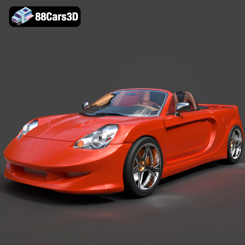
Download the Toyota MRS-007 3D Model featuring clean geometry, realistic detailing, and a fully modeled interior. Includes .blend, .fbx, .obj, .glb, .stl, .ply, .unreal, and .max formats for rendering, simulation, and game development.
Price: $10
View Product

Texture: Yes
Material: Yes
Download the Porsche 911 Turbo S 2024 3D Model featuring clean geometry, realistic detailing, and a fully modeled interior. Includes .blend, .fbx, .obj, .glb, .stl, .ply, .unreal, and .max formats for rendering, simulation, and game development.
Price: $20
View Product

Texture: Yes
Material: Yes
Download the Pontiac Solstice 2009 3D Model featuring clean geometry, realistic detailing, and a fully modeled interior. Includes .blend, .fbx, .obj, .glb, .stl, .ply, .unreal, and .max formats for rendering, simulation, and game development.
Price: $10
View Product

Texture: Yes
Material: Yes
Download the Mini Cooper Countryman 2025 3D Model featuring clean geometry, realistic detailing, and a fully modeled interior. Includes .blend, .fbx, .obj, .glb, .stl, .ply, .unreal, and .max formats for rendering, simulation, and game development.
Price: $29.9
View Product
Texture: Yes
Material: Yes
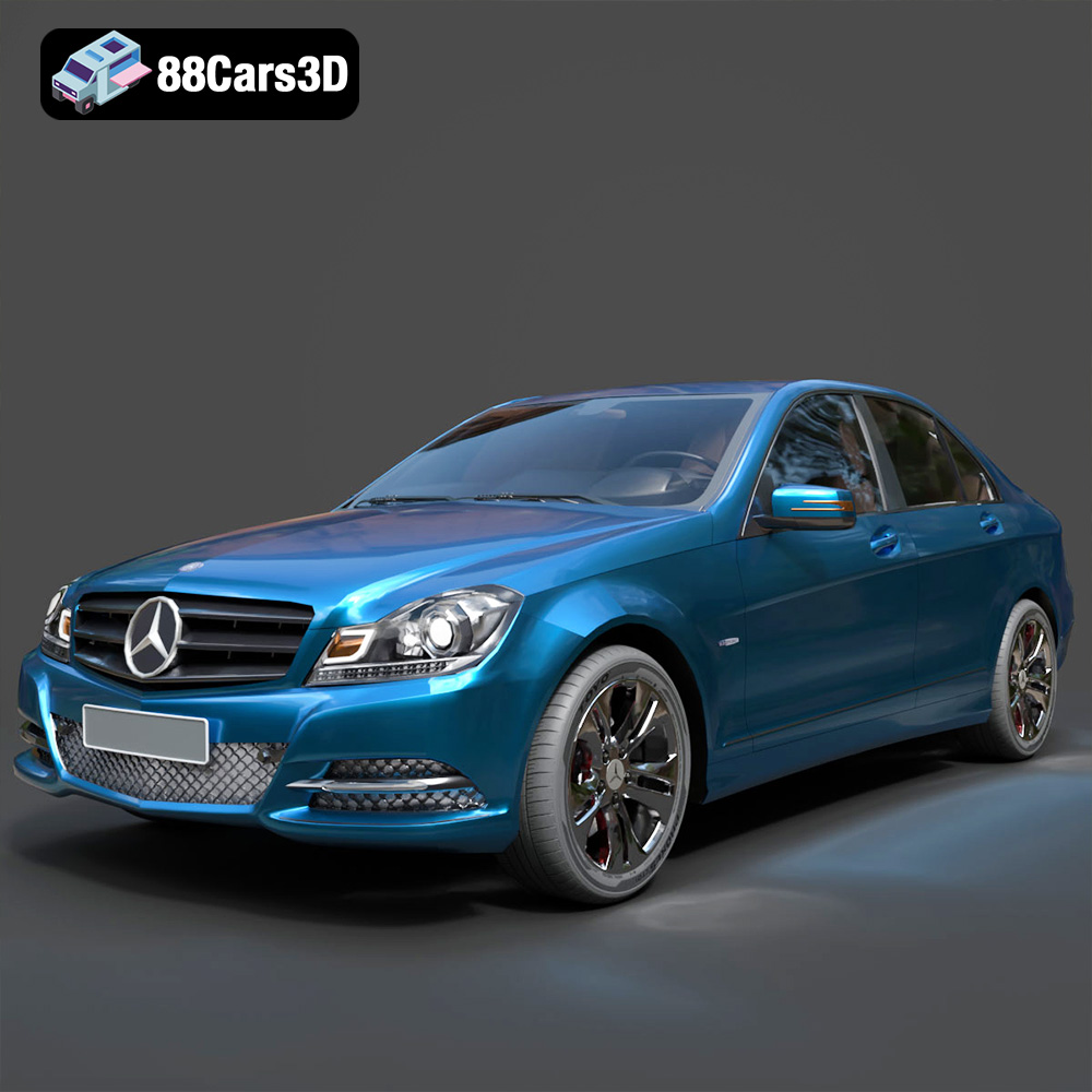
Download the Mercedes C Classe 2012 3D Model featuring clean geometry, realistic detailing, and a fully modeled interior. Includes .blend, .fbx, .obj, .glb, .stl, .ply, .unreal, and .max formats for rendering, simulation, and game development.
Price: $19.9
View Product
Texture: Yes
Material: Yes
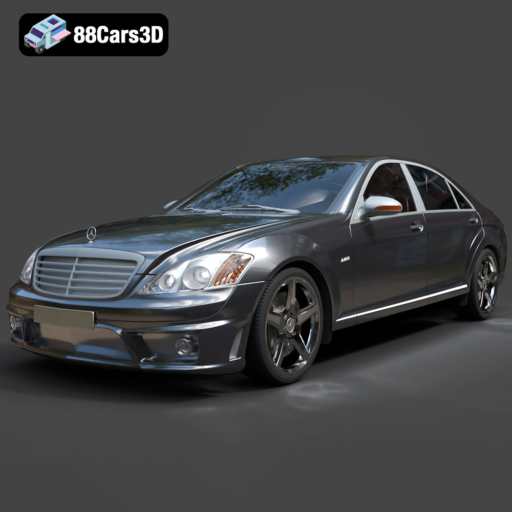
Download the Mercedes-Benz S65 AMG 2018 3D Model featuring clean geometry, realistic detailing, and a fully modeled interior. Includes .blend, .fbx, .obj, .glb, .stl, .ply, .unreal, and .max formats for rendering, simulation, and game development.
Price: $19.9
View Product
Texture: Yes
Material: Yes
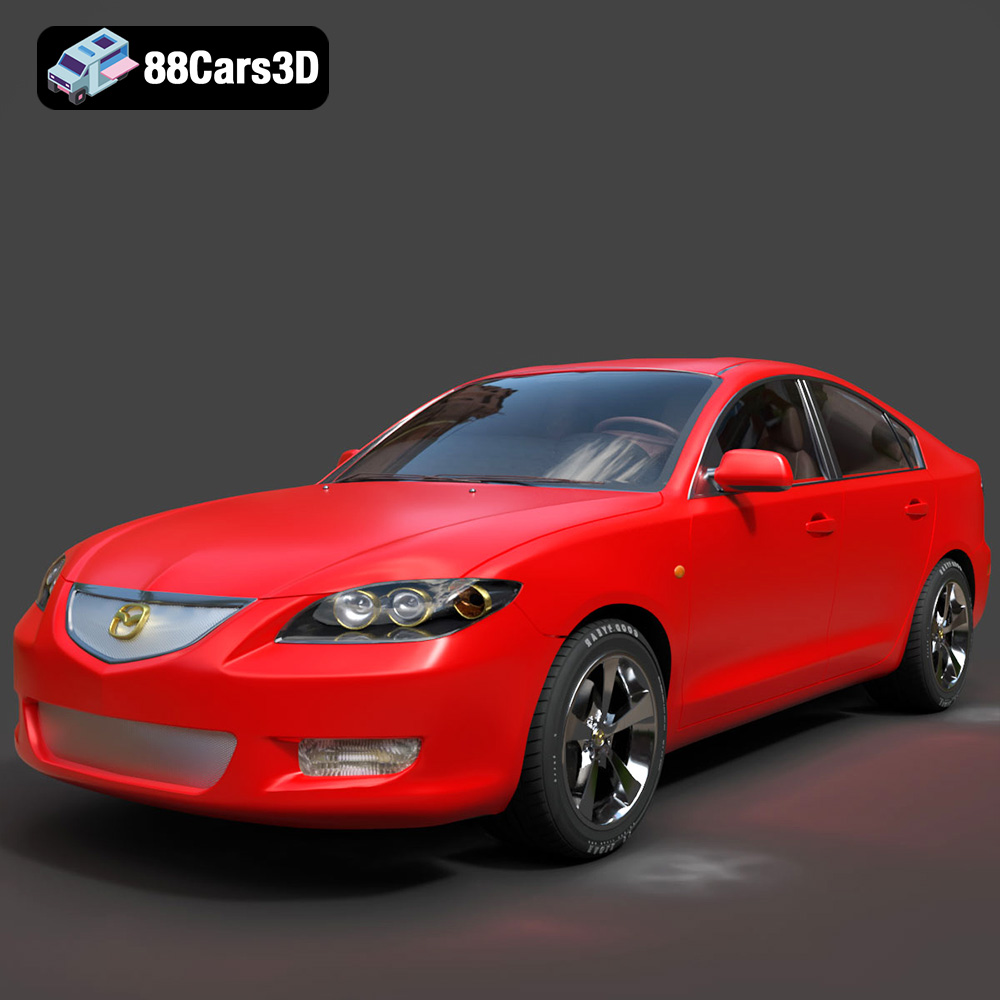
Download the Mazda 3 Sedan 2004 3D Model featuring clean geometry, realistic detailing, and a fully modeled interior. Includes .blend, .fbx, .obj, .glb, .stl, .ply, .unreal, and .max formats for rendering, simulation, and game development.
Price: $10
View Product

Texture: Yes
Material: Yes
Download the Martin Rapide 2011 3D Model featuring clean geometry, realistic detailing, and a fully modeled interior. Includes .blend, .fbx, .obj, .glb, .stl, .ply, .unreal, and .max formats for rendering, simulation, and game development.
Price: $20.9
View Product
Texture: Yes
Material: Yes
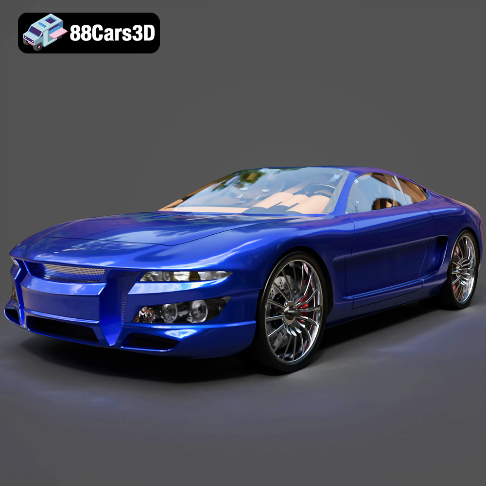
Download the Car Tasergal 005 3D Model featuring clean geometry, realistic detailing, and a fully modeled interior. Includes .blend, .fbx, .obj, .glb, .stl, .ply, .unreal, and .max formats for rendering, simulation, and game development.
Price: $10
View Product
Texture: Yes
Material: Yes
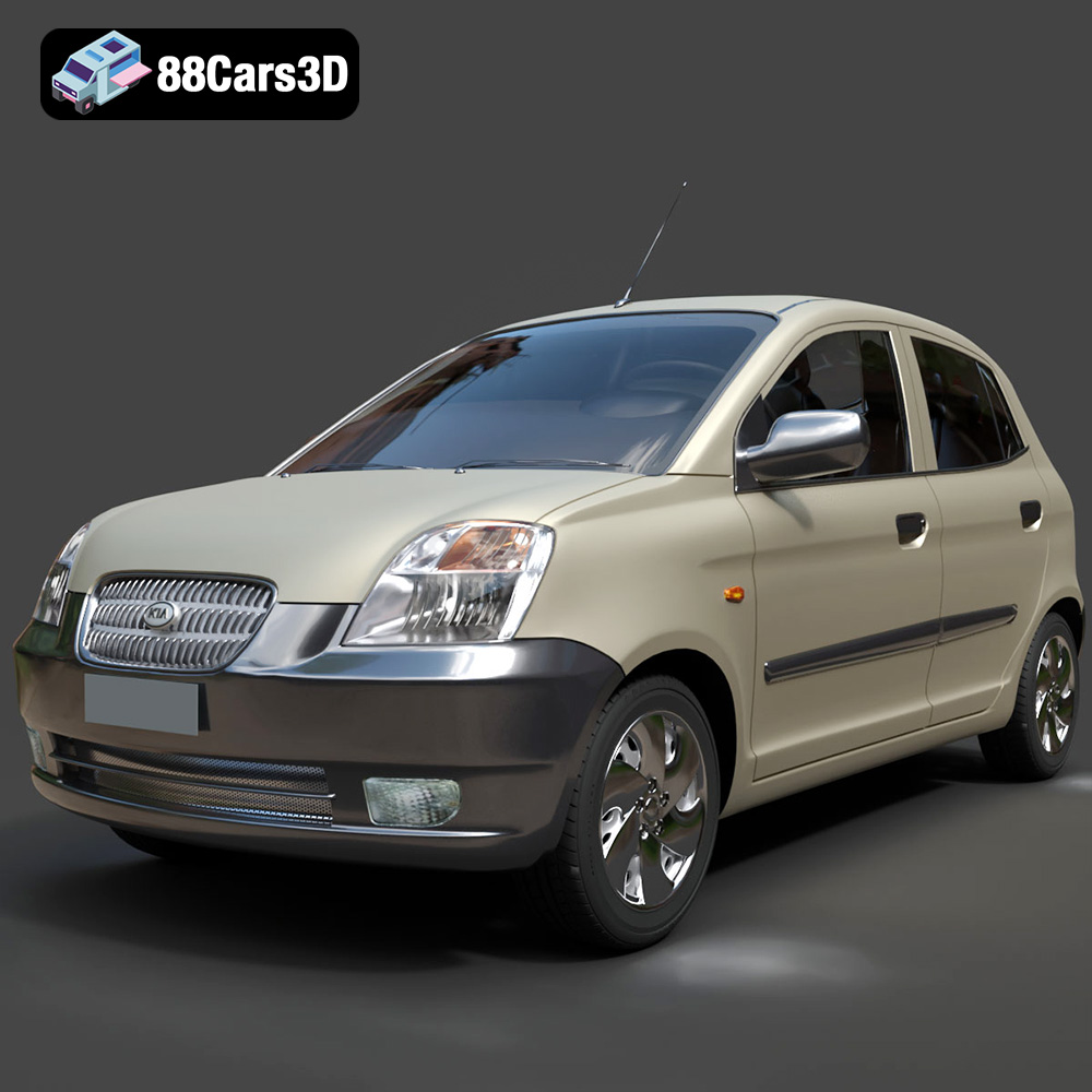
Download the Kia Picanto 2024 3D Model featuring clean geometry, realistic detailing, and a fully modeled interior. Includes .blend, .fbx, .obj, .glb, .stl, .ply, .unreal, and .max formats for rendering, simulation, and game development.
Price: $15.99
View Product