
Mastering Your 3D Prints: A Deep Dive into STL File Preparation with Blender
The world of 3D printing is an exciting frontier, where digital designs transform into tangible objects. At the heart of this process lies the STL (STereoLithography) file format, the universal language for 3D printers. While many online platforms, such as 88cars3d.com, offer meticulously crafted, print-ready STL files for automotive enthusiasts, even the best models can sometimes benefit from a little fine-tuning. Whether you’re aiming for flawless FDM prints or pristine resin casts, understanding how to clean up and prepare your STL files is a crucial skill. This comprehensive guide will walk you through the essential steps of STL file preparation, focusing on the powerful and versatile capabilities of Blender, a free and open-source 3D creation suite. We’ll explore everything from understanding mesh topology and common STL errors to advanced slicing techniques and post-processing magic, ensuring your 3D printed car models are nothing short of spectacular.
Understanding the Anatomy of an STL File
Before we dive into the cleaning process, it’s essential to grasp what an STL file actually is and why it matters for 3D printing. Unlike other 3D file formats that can store rich data like color and texture, STL files are intentionally simple. They represent a 3D surface geometry as a collection of interconnected triangles, also known as facets. Each triangle is defined by its three vertices and a normal vector, which indicates the outward-facing direction of the surface. This simplicity is what makes STL files universally compatible with most 3D printing software and hardware. However, this simplicity can also be a source of issues if the mesh isn’t “watertight” or contains geometric errors.
Mesh Topology: The Foundation of Printability
The term “mesh topology” refers to how the vertices, edges, and faces of a 3D model are connected. For a 3D printable model, the mesh must form a **manifold** or **watertight** volume. This means there should be no holes, no internal faces, and no edges shared by more than two faces. Think of it like a balloon: it needs to be fully sealed to hold air. If there are holes, your slicer software might interpret them as internal voids, leading to print failures, under-extrusion, or hollow-looking sections.
- Manifold Geometry: Every edge must connect exactly two faces. This ensures a continuous surface without gaps or self-intersections.
- Non-Manifold Edges: These are edges connected to more than two faces, often indicating internal walls or strange geometry that can confuse slicers.
- Holes/Gaps: Openings in the mesh that break the watertight seal. These are common issues that need careful repair.
- Internal Faces: Triangles facing inwards, contributing to unnecessary complexity and potential print artifacts.
Common STL Errors and Their Impact on Printing
When downloading models, especially from diverse marketplaces, you might encounter various issues that can derail your printing efforts. Understanding these common STL errors will help you identify and fix them efficiently using tools like Blender.
- Non-Manifold Vertices: Vertices where multiple edges meet at sharp angles, often creating internal geometry.
- Degenerate Faces: Triangles with zero area (e.g., all vertices are the same point) or triangles where vertices are collinear (forming a line instead of a plane).
- Self-Intersections: Parts of the mesh crossing over themselves, creating invalid geometry that slicers cannot process correctly.
- Inverted Normals: Facets whose normal vectors point inwards instead of outwards. Slicers may interpret these areas as hollow or missing.
- Disconnected Components: Separate pieces of geometry that are not connected, effectively creating multiple smaller models instead of one unified object.
These errors can manifest in your prints as missing sections, unexpected blobs, weak points, or even complete print failures. Proactive mesh repair is therefore an indispensable part of the 3D printing workflow.
Blender: Your Free Gateway to STL Mesh Repair
Blender is a professional-grade, open-source 3D creation suite renowned for its powerful modeling, sculpting, animation, and rendering capabilities. What makes it particularly attractive for 3D printing enthusiasts is its robust mesh editing toolkit, which can be leveraged for detailed STL file preparation and repair—all without the cost of proprietary software. While it has a steeper learning curve than some dedicated mesh repair tools, its flexibility and depth are unmatched. Platforms like 88cars3d.com often provide models in a well-prepared state, but for custom modifications or troubleshooting tricky files, Blender is an invaluable asset.
Setting Up Blender for STL Workflows
Getting Blender ready for STL file manipulation is straightforward. You’ll primarily be working in **Edit Mode** with the mesh data.
- Importing STL Files: Navigate to
File > Import > STL (.stl). Select your STL file. - Understanding the Interface: Familiarize yourself with the 3D Viewport, the Outliner (to see your imported objects), and the Properties panel.
- Entering Edit Mode: Select your imported model in the 3D Viewport and press the
Tabkey to switch between Object Mode and Edit Mode. In Edit Mode, you can manipulate individual vertices, edges, and faces. - Navigation and Selection Tools: Learn to use the mouse and keyboard shortcuts for orbiting, panning, zooming, and selecting elements (
Gfor grab/move,Rfor rotate,Sfor scale,Ato select all,Bfor box select,Cfor circle select).
Essential Blender Tools for Mesh Cleanup
Blender offers a suite of tools specifically designed for mesh manipulation that are highly effective for STL repair.
- Merge Vertices: Found under the
Mesh > Clean Upmenu or by pressingMin Edit Mode. This is crucial for removing duplicate vertices that can create non-manifold geometry. Common options include “By Distance” (merges vertices within a specified proximity) and “By Distance (Weld)” which is often more reliable. - Recalculate Normals: Access this via
Mesh > Normals > Recalculate Outside(shortcutShift + N). This ensures all faces are oriented correctly, preventing issues with slicers interpreting surfaces as inside-out. - Remove Doubles: Similar to Merge Vertices, this is found under
Mesh > Clean Up > Merge by Distance. It’s a fundamental step to consolidate overlapping geometry. - Mesh > Clean Up Options: Explore options like “Limited Dissolve” (simplifies geometry while preserving major features) and “Make Manifold” (attempts to automatically fix non-manifold issues, though often requires manual follow-up).
These tools, when used systematically, form the backbone of your STL cleaning process.
Step-by-Step STL File Repair in Blender
Now, let’s put these tools into practice with a structured workflow. The goal is to achieve a **watertight** and **manifold** mesh that your slicer can interpret without errors.
Phase 1: Initial Assessment and Basic Cleanup
Before diving into complex fixes, perform a quick assessment and apply fundamental cleanup operations.
- Import and Inspect: Import your STL file into Blender. In Edit Mode, use
Alt + Ato deselect everything, thenAto select all. Look for any visual anomalies or disconnected parts in the 3D Viewport. - Remove Doubles: With all vertices selected, go to
Mesh > Clean Up > Merge by Distance. Start with a small distance value (e.g., 0.0001m) and gradually increase it until overlapping vertices merge without compromising the model’s details. A larger distance can merge unintentionally. - Recalculate Normals: Ensure all faces point outwards by selecting everything in Edit Mode and pressing
Shift + N. If some faces remain dark or oddly shaded, you might need to manually flip their normals by selecting them and pressingCtrl + N(orShift + Nfor flip inside).
Phase 2: Identifying and Fixing Non-Manifold Geometry
Non-manifold geometry is a common culprit for print failures. Blender’s selection tools can help isolate these problematic areas.
- Select Non-Manifold: In Edit Mode, go to
Select > Select All by Trait > Non Manifold. This will highlight all problematic edges and vertices. - Analyze and Repair:
- Holes: If holes are selected, you can manually close them. Select the boundary loop of the hole (
Alt + Clickon an edge) and pressFto create a new face. For complex holes, you might need to add edge loops (Ctrl + R) and manually connect vertices. - Internal Faces: These appear as faces within the solid body. Select them and press
X > Facesto delete them. - Manifold Edges: Edges shared by more than two faces. These often require careful manual cleanup. You might need to dissolve edges (
X > Dissolve Edges) and reconnect vertices to form a clean manifold structure.
- Holes: If holes are selected, you can manually close them. Select the boundary loop of the hole (
- Add Modifier (Optional but Recommended): The “3D-Print Toolbox” add-on, built into Blender, can automate some checks. Enable it via
Edit > Preferences > Add-onsand search for “3D-Print Toolbox”. It provides a panel in the 3D Viewport (pressNto open) with tools to check for overhangs, wall thickness, and manifold errors, often highlighting issues more clearly. - Check for Intersections: While Blender doesn’t have a single button for “fix self-intersections,” visual inspection is key. Sometimes, intersecting geometry can be fixed by deleting the intersecting faces and rebuilding the surface. Tools like the Knife tool (
K) or Boolean operations (using the modifier stack, though be cautious as Booleans can create new issues) can help. - Decimation for Complexity: If your model is excessively dense with triangles (high poly count), it can slow down slicing. Use the
Decimatemodifier (Add Modifier > Decimate) to reduce the poly count. Use the “Collapse” mode and adjust theRatio. Be careful not to reduce it too much, as this can lose fine details. - Wall Thickness: For successful prints, especially with resin printers, ensuring adequate wall thickness is vital. The 3D-Print Toolbox add-on has a “Check All Walls” feature that highlights areas below a specified minimum thickness. You can then thicken these areas manually or using the Solidify modifier.
- Understanding Overhangs: Most slicers have a setting to visualize overhangs beyond a certain angle (e.g., 45 degrees). Areas exceeding this threshold will require support.
- Model Orientation: The way you orient the model on the print bed dramatically affects the amount and placement of supports needed. For complex car models, consider orientations that minimize overhangs on visible surfaces. For example, printing a car body upright might require extensive supports on the undercarriage, while tilting it can reduce this.
- Support Type: Slicers offer various support types:
- Normal/Grid: Standard supports.
- Tree/Organic: Often preferred for complex models as they use less material and are easier to remove, branching out like trees.
- Custom Supports: Some advanced slicers allow placing manual support points.
- Support Settings: Fine-tune settings like Support Density (how solid the supports are), Support Wall Thickness, Support Pattern, and Support Interface Layers (a denser layer at the top of supports to create a smoother surface finish on the model). Experimentation is key here. A good starting point for FDM might be 10-15% density and 0.2mm interface layers.
- Strategic Placement: Rotate and position your model in the slicer to minimize overhangs, avoid supports on critical details (like tire treads or body panels), and ensure a stable base. For car models, consider placing the largest, flattest surface (e.g., the roof or undercarriage) against the print bed if possible.
- Bed Adhesion Techniques:
- Brim: Adds a single layer of extruded material around the base of the print, increasing surface area for better adhesion. Ideal for models with small footprints or sharp corners.
- Raft: Prints a dense grid of material beneath the model, providing a stable foundation. Useful for problematic materials or uneven build surfaces.
- Skirt: Extrudes a few lines around the model without touching it. Primarily used to prime the nozzle and check filament flow before the actual print begins.
- Slicer Software: Popular slicers like Cura, PrusaSlicer, and Simplify3D offer intuitive tools for rotating, scaling, and placing models. Understanding their interfaces is crucial for optimizing orientation.
- FDM Materials:
- PLA: Easy to print, good detail, relatively brittle. Excellent for static display models. Layer height: 0.1-0.2mm. Print Temp: 190-220°C. Bed Temp: 50-60°C.
- PETG: More durable and temperature-resistant than PLA, slightly harder to print due to stringing. Good for functional parts. Layer height: 0.15-0.25mm. Print Temp: 230-250°C. Bed Temp: 70-85°C.
- ABS: Strong, high-temperature resistance, but prone to warping and requires an enclosed printer. Layer height: 0.15-0.2mm. Print Temp: 240-260°C. Bed Temp: 90-110°C.
- Resin (SLA/DLP) Materials:
- Standard Resins: Offer high detail and smooth surfaces. Ideal for intricate car models. Layer height: 0.025-0.05mm. Exposure times vary significantly by resin and printer.
- Tough/ABS-like Resins: Provide increased durability and impact resistance.
- Key Slicer Settings:
- Layer Height: Lower values (e.g., 0.1mm for FDM, 0.025mm for resin) result in finer detail but longer print times. Higher values (e.g., 0.2mm for FDM) print faster but show more visible layer lines. For detailed car models, 0.1-0.15mm is often a good balance for FDM.
- Infill Density and Pattern: For display models, 10-20% infill is usually sufficient. Patterns like Gyroid or Cubic offer good strength-to-weight ratios. Higher infill increases print time and material usage.
- Print Speed: Slower speeds generally yield better quality, especially for outer walls. Consider speeds around 40-60 mm/s for outer walls on FDM printers.
- Tools: Needle-nose pliers, flush cutters, hobby knives (X-Acto knives), dental picks, and sometimes small files or sanding sticks are essential.
- Technique: For FDM prints, gently break away larger support sections with pliers. Use flush cutters to snip away smaller contact points. For resin prints, supports are often thinner and can be carefully cut away with a hobby knife. Always wear safety glasses, especially when cutting or sanding.
- Sanding: Start with coarser grit sandpaper (e.g., 150-220 grit) to remove support marks and layer lines, progressing to finer grits (400, 800, 1000+) for a smooth finish. Wet sanding can help reduce dust and achieve a smoother surface.
- Filling Gaps: Use modeling putty (e.g., Tamiya Putty, Green Stuff) or automotive filler primer to fill any small gaps, layer lines, or support contact points. Sand smooth after drying.
- Priming: Apply a thin, even coat of primer (spray primer is recommended). Primer helps reveal imperfections that need further sanding and provides a uniform surface for paint adhesion. Use light coats to avoid obscuring fine details.
- Painting: Acrylic model paints are versatile and widely available. Use an airbrush for smooth, even coats or fine brushes for details. Automotive spray paints can also be used for base coats. Research the specific paint types and techniques for achieving realistic automotive finishes.
- Alignment Aids: Many models include pins, sockets, or alignment keys to help ensure parts fit together correctly.
- Adhesives: Cyanoacrylate (super glue) is excellent for fast bonding of most plastics. For FDM prints, plastic cement or even solvent welding (using acetone for ABS, though use with extreme caution and ventilation) can create very strong bonds. For resin prints, UV resin or super glue works well.
- Test Fitting: Always dry-fit parts before applying glue to ensure a perfect fit. Minor adjustments with a hobby knife or sandpaper might be necessary.
Phase 3: Addressing Intersecting Geometry and Refinements
Self-intersections and overly complex geometry can also cause slicing issues.
Advanced Techniques for Optimal Print Quality
Beyond basic cleanup, advanced preparation can significantly improve the outcome of your 3D prints, turning a good model into a great one. This involves strategic decisions about how the model will be sliced and printed.
Support Structure Generation: The Unsung Hero
Support structures are temporary scaffolding printed alongside your model to hold up overhangs and bridges that would otherwise collapse. Generating effective supports is an art, and proper STL preparation makes it easier.
Print Orientation and Bed Adhesion: The Foundation of Success
The orientation of your model on the print bed influences print time, support requirements, surface quality, and adhesion. Bed adhesion is critical to prevent prints from detaching mid-print.
Material Selection and Printer Settings: Tailoring for Your Model
The choice of material and corresponding printer settings will significantly impact the final appearance and durability of your 3D printed car.
Post-Processing: Bringing Your 3D Printed Car to Life
Once your model is printed, the journey isn’t over. Post-processing is where you refine the print, enhance its details, and achieve a professional finish.
Support Removal and Surface Finishing
Careful removal of support structures is crucial to avoid damaging the model.
Filling, Priming, and Painting
These steps transform a raw print into a realistic model.
Assembly of Multi-Part Models
Many complex car models, especially those from marketplaces like 88cars3d.com, are designed in multiple parts for easier printing and assembly.
Conclusion: Your 3D Printed Masterpiece Awaits
Mastering STL file preparation is a transformative skill for any 3D printing enthusiast. From understanding the fundamental structure of STL files to leveraging the powerful capabilities of Blender for mesh repair, each step contributes to the success of your prints. By systematically cleaning your models, strategically orienting them, optimizing slicer settings, and employing careful post-processing techniques, you can elevate your 3D printed car models from mere replicas to stunning displays of craftsmanship. Remember, even the highest quality STL files from sources like 88cars3d.com can sometimes benefit from a personal touch, especially when aiming for specific aesthetic outcomes or troubleshooting elusive print issues. Embrace the process, experiment with settings, and don’t be afraid to iterate. With practice and attention to detail, your 3D printer will become a powerful tool for bringing your automotive passion to life, one perfectly printed layer at a time.
Featured 3D Car Models
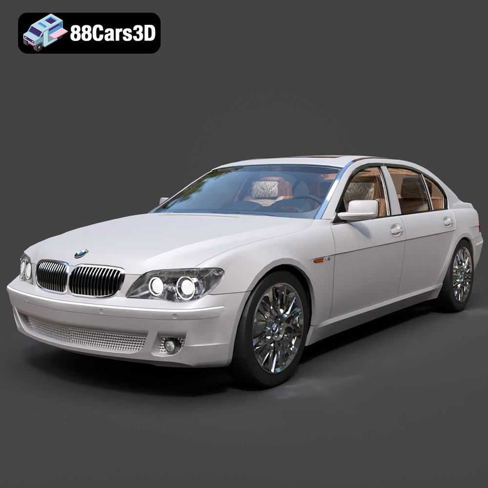
BMW 760Li E66 2005 3D Model
Texture: Yes
Material: Yes
Download the BMW 760Li E66 2005 3D Model featuring a detailed exterior, refined interior, and robust chassis. Includes .blend, .fbx, .obj, .glb, .stl, .ply, .unreal, and .max formats for rendering, simulation, and game development.
Price: $10.79

BMW 6 Series 3D Model
Texture: Yes
Material: Yes
Download the BMW 6 Series 3D Model featuring precisely modeled body panels, detailed interior, and authentic wheels. Includes .blend, .fbx, .obj, .glb, .stl, .ply, .unreal, and .max formats for rendering, simulation, and game development.
Price: $10.79

BMW M6 Coupe (F12) 3D Model
Texture: Yes
Material: Yes
Download the BMW M6 Coupe (F12) 3D Model featuring its iconic sporty design and luxurious details. Includes .blend, .fbx, .obj, .glb, .stl, .ply, .unreal, and .max formats for rendering, simulation, and game development.
Price: $10.79

BMW M5 F10 3D Model
Texture: Yes
Material: Yes
Download the BMW M5 F10 3D Model featuring high-performance luxury sedan design, detailed interior, and realistic PBR textures. Includes .blend, .fbx, .obj, .glb, .stl, .ply, .unreal, and .max formats for rendering, simulation, and game development.
Price: $10.79

BMW M3 Coupe E92-002 3D Model
Texture: Yes
Material: Yes
Download the BMW M3 Coupe E92-002 3D Model featuring authentic styling, detailed exterior, and a faithful interior. Includes .blend, .fbx, .obj, .glb, .stl, .ply, .unreal, and .max formats for rendering, simulation, and game development.
Price: $10.79

BMW 6 Series Gran Coupe 2013 3D Model
Texture: Yes
Material: Yes
Download the BMW 6 Series Gran Coupe 2013 3D Model featuring a sophisticated design, detailed exterior, and well-appointed interior. Includes .blend, .fbx, .obj, .glb, .stl, .ply, .unreal, and .max formats for rendering, simulation, and game development.
Price: $20.79

BMW 7 Series 750 F01 3D Model
Texture: Yes
Material: Yes
Download the BMW 7 Series 750 F01 3D Model featuring a detailed exterior and a luxurious interior. Includes .blend, .fbx, .obj, .glb, .stl, .ply, .unreal, and .max formats for rendering, simulation, and game development.
Price: $10.79
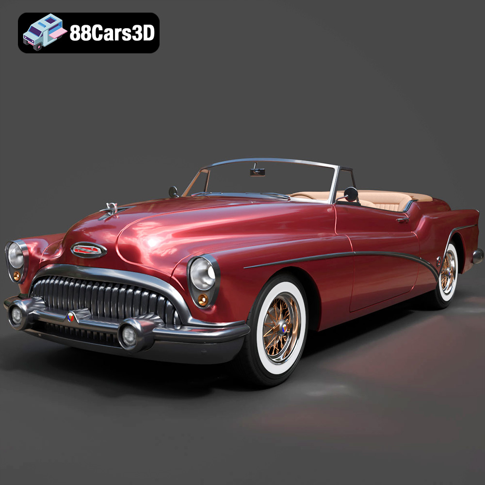
Buick Skylark Convertible 1953 3D Model
Texture: Yes
Material: Yes
Download the Buick Skylark Convertible 1953 3D Model featuring iconic 1950s styling, a detailed exterior with chrome accents, and an accurately modeled interior. Includes .blend, .fbx, .obj, .glb, .stl, .ply, .unreal, and .max formats for rendering, simulation, and game development.
Price: $10.79

Buick Roadmaster Hardtop Coupe 1957 3D Model
Texture: Yes
Material: Yes
Download the Buick Roadmaster Hardtop Coupe 1957 3D Model featuring a classic American design with detailed exterior and interior. Includes .blend, .fbx, .obj, .glb, .stl, .ply, .unreal, and .max formats for rendering, simulation, and game development.
Price: $10.79
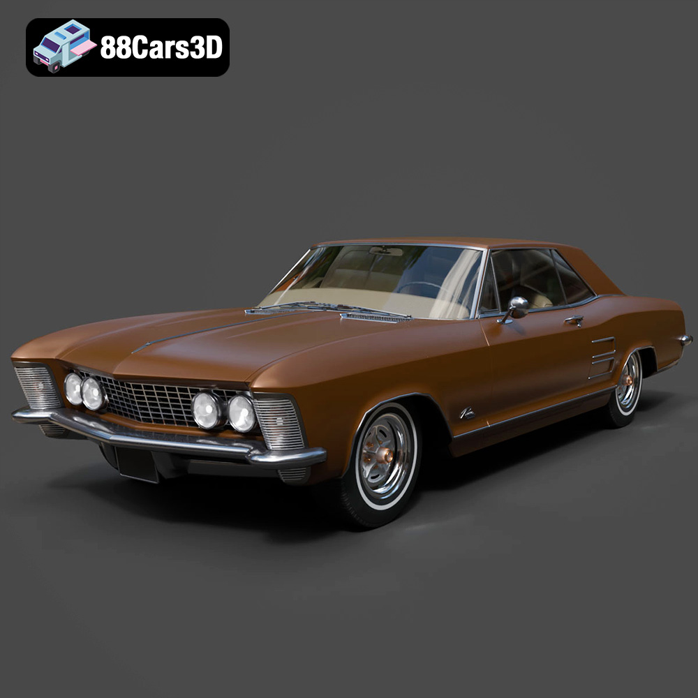
Buick Riviera 1963 3D Model
Texture: Yes
Material: Yes
Download the Buick Riviera 1963 3D Model featuring classic American muscle car design and iconic styling. Includes .blend, .fbx, .obj, .glb, .stl, .ply, .unreal, and .max formats for rendering, simulation, and game development.
Price: $10.79
