
The roar of an engine, the sleek lines of a supercar, the timeless elegance of a classic — automotive design captivates enthusiasts worldwide. For 3D artists and designers, translating this passion into tangible creations has historically been confined to screens. However, with the advent of accessible and sophisticated 3D printing technology, the boundaries between digital and physical are blurring. Now, your meticulously crafted 3D car models, once destined solely for stunning renders or interactive game assets, can be brought to life as physical prototypes, collectibles, or even functional components.
Preparing a digital 3D model for the physical rigors of 3D printing is a specialized skill set. It requires a deep understanding of mesh integrity, material properties, and the unique constraints of additive manufacturing. This comprehensive guide will navigate you through the essential technical steps, from ensuring watertight topology to optimizing file formats, to transform your virtual automotive masterpieces into print-ready objects. Whether you’re a seasoned automotive designer, a game developer looking to prototype, or a hobbyist eager to hold your digital creations, mastering these techniques will unlock a new dimension for your work, ensuring your 3D car models emerge from the printer exactly as you envisioned.
Understanding 3D Printability: Core Principles of a Robust Mesh
Before diving into specific software techniques, it’s crucial to grasp the fundamental principles that define a “3D printable” model. Unlike automotive rendering or visualization, where a model’s visual fidelity is paramount, 3D printing demands structural integrity and geometric precision. A beautiful render can mask numerous topological flaws, but a 3D printer will ruthlessly expose them, leading to failed prints, inaccuracies, or fragile results. Understanding these core concepts is the first step toward successful additive manufacturing.
Manifold Meshes: The Watertight Foundation
The most critical concept in 3D printing preparation is that of a “manifold” or “watertight” mesh. Imagine your 3D model as a hollow shell that needs to hold water. If there are any holes, gaps, or internal faces, the water would leak out. A 3D printer needs to understand what is “inside” and “outside” your model to correctly lay down material. A non-manifold mesh, characterized by issues like unmerged vertices, open edges, flipped normals, or intersecting faces, creates ambiguity for the slicer software, leading to errors. Each edge in a manifold mesh should be shared by exactly two faces. Deviations from this rule are red flags that must be addressed.
Wall Thickness: Ensuring Structural Integrity
Just as a real car needs a certain gauge of metal for its body panels, a 3D printed model requires adequate wall thickness to maintain structural integrity. Too thin, and your model will be fragile, prone to breaking during or after printing, or even impossible for the printer to resolve. The minimum wall thickness is highly dependent on the chosen 3D printing technology (FDM, SLA, SLS) and material. For standard FDM printing, a minimum of 0.8mm to 1.2mm is often recommended, roughly equivalent to two nozzle widths. For SLA resins, even thinner walls (down to 0.5mm) might be achievable, but always consult the specifications of your specific printer and material. Critically examine small details like antenna, mirrors, or spoilers on your 3D car models to ensure they meet minimum thickness requirements.
Scale and Resolution: Detail vs. Printability
The scale of your model directly impacts its printability and the level of detail achievable. A highly detailed 3D car model designed for large-scale automotive rendering might have intricate grilles or fine trim that become microscopically small when scaled down for a desktop printer. Ensure your model’s units in your 3D software (e.g., millimeters or inches) correspond to the real-world dimensions you desire for the final print. Related to this is mesh resolution (polygon count). While higher polygon counts allow for smoother curves and finer details, excessively dense meshes can lead to unnecessarily large file sizes and longer processing times for slicers. For most FDM prints, a resolution that provides smooth curves without excessive polygon density is ideal, typically aiming for polygon counts that are detailed enough but avoid microscopic triangles that a printer can’t accurately reproduce. Striking a balance between visual fidelity and printability is key.
Topology and Mesh Repair for Impeccable Prints
The topology of your 3D car model is the blueprint for its physical form. For 3D printing, a clean, error-free mesh is non-negotiable. Even models optimized for game assets might possess topological shortcuts or optimizations that are detrimental to 3D printing. This section will delve into identifying common mesh issues and the essential repair workflows using popular 3D software.
Identifying Common Mesh Issues
Before you can fix a problem, you need to find it. Common culprits for non-manifold meshes include:
- Open Edges/Holes: Unclosed boundaries where surfaces should connect.
- Flipped Normals: Faces pointing inwards instead of outwards, confusing the printer about which side is “solid.”
- Intersecting/Overlapping Geometry: Two or more surfaces occupying the same space, creating ambiguous volume.
- Internal Geometry: Faces or volumes entirely contained within the model, adding unnecessary complexity and potential errors.
- Non-Manifold Edges/Vertices: Edges shared by more than two faces, or vertices with disconnected geometry.
- Zero-Thickness Walls: Surfaces with no volume, impossible to print.
- Loose Parts: Disconnected mesh components that are not intended to be separate.
Many 3D software packages offer analysis tools to highlight these issues. For example, in Blender, the 3D Print Toolbox addon (built-in, needs to be enabled) is invaluable for checking manifold status, overhangs, wall thickness, and intersections. It provides a visual overlay to pinpoint exact problem areas.
Repair Workflows in Blender (Blender 4.4 Documentation Reference)
Blender is an incredibly powerful tool for 3D modeling and preparing models for print. Here’s a typical workflow:
- Enable 3D Print Toolbox: Go to
Edit > Preferences > Add-onsand search for “3D Print Toolbox.” Enable it. - Select Model & Analyze: In Object Mode, select your 3D car model. In the N-Panel (press ‘N’), navigate to the ‘3D Print’ tab. Click ‘Check All’ to run a comprehensive analysis.
- Fix Non-Manifold Edges: The toolbox will highlight non-manifold edges. Often, these are caused by unmerged vertices. In Edit Mode, select all vertices (A), then use
Mesh > Clean Up > Merge by Distance(previously “Remove Doubles”) with a small threshold. This merges overlapping vertices. - Fill Holes: If you have open boundaries, select the loop of open edges in Edit Mode, then press ‘F’ to fill a single face, or use
Face > Fillfor more complex holes. The 3D Print Toolbox’s ‘Make Manifold’ button can sometimes automatically fix minor holes and open edges. For more control, refer to Blender 4.4’s documentation on creating faces and edges. - Recalculate Normals: Flipped normals are common. In Edit Mode, select all faces (A) and press
Shift+N(orMesh > Normals > Recalculate Outside) to ensure all normals point consistently outwards. - Remove Internal Geometry: This is trickier. You might need to use Boolean operations (
Object > Boolean > Difference) or manually delete faces that are completely enclosed and not contributing to the outer shell. - Wall Thickness Check: Use the 3D Print Toolbox’s ‘Thickness’ check. It will highlight areas below your specified minimum wall thickness. You may need to manually extrude these areas or apply a solidify modifier.
Advanced Repair Techniques and Considerations
For highly complex 3D car models, especially those with intricate interiors or overlapping components, manual repair can be time-consuming. Here are some advanced strategies:
- Boolean Operations: For models composed of multiple intersecting parts, use Boolean modifiers (Union, Difference) to combine them into a single, watertight mesh. Be cautious, as Booleans can sometimes introduce messy topology, requiring post-Boolean cleanup.
- Remeshing: Tools like Blender’s Remesh Modifier can convert complex, messy geometry into a clean, uniform voxel or quad-based mesh. This is particularly useful for sculptural or organic forms, though it can alter fine details on hard-surface models if not used carefully.
- Specialized Software: For particularly stubborn meshes, dedicated mesh repair software like Netfabb, Meshmixer, or Magics can provide powerful automated repair tools that go beyond standard 3D modeling packages. These are often used in professional 3D printing environments.
- Slicer Software Repair: Many slicer programs (e.g., Cura, PrusaSlicer, Simplify3D) have built-in mesh repair algorithms. While useful for minor issues, it’s always best practice to fix problems in your 3D modeling software first for maximum control and reliability.
Always re-check your model after each significant repair step to ensure new issues haven’t been introduced. This iterative process of identification and correction is key to achieving a truly print-ready mesh.
Scaling, Orientation, and Support Structures: Optimizing for the Print Bed
Once your 3D car model boasts a flawless, watertight mesh, the next crucial steps involve preparing it for the physical constraints of the 3D printer itself. This includes setting the correct scale, determining the optimal print orientation, and strategizing for necessary support structures. These decisions profoundly impact print quality, material usage, and print time.
Achieving Accurate Scale for Your Automotive Models
The first step in preparing your model for the print bed is to define its real-world dimensions. Digital 3D modeling environments often operate in arbitrary units, or units not natively understood by the slicer. Before exporting, ensure your model is scaled correctly within your 3D software. If you’ve designed a 1:24 scale model of a real car, ensure that its dimensions in your software (e.g., 180mm length for a typical car at that scale) translate directly to the desired output. Most 3D printing software will allow you to scale models, but it’s best practice to export at the correct scale from your modeling application. For precision, double-check dimensions in your slicer software after importing. Remember, the smaller the scale, the more challenging it becomes to print fine details and thin walls, reinforcing the importance of our earlier discussion on wall thickness.
Optimal Print Orientation for Strength and Detail
The orientation of your 3D car model on the print bed is critical for several reasons: print quality, structural integrity, and minimizing (or strategically placing) support material. When using FDM printers, prints are weakest along the Z-axis (layer lines). Therefore, orienting a model to distribute stress across layers, or to maximize strength in a critical direction, is important. For instance, printing a car chassis flat on its base generally provides the strongest foundation. Overhangs, areas of your model that extend outwards without material directly beneath them, require support. Minimizing the need for supports, or placing them in less visible or easily removable areas, is a key optimization. Consider rotating your car model to reduce severe overhangs (e.g., bumpers, spoilers, wheel arches) and to present the most critical, highly detailed surfaces upwards, where print quality is typically highest. Experiment with different orientations in your slicer to visually assess support generation and overhang angles.
Support Structure Strategies for Complex Car Geometries
Complex 3D car models, with their intricate curves, undercuts, and fine details, almost always require support structures. These temporary structures prevent drooping and ensure accurate geometry during printing. Modern slicer software offers various support types (e.g., tree supports, linear supports, custom supports) and settings (density, angle threshold, contact Z distance). For automotive models, common areas requiring support include:
- Undersides of bumpers and spoilers.
- Wheel arches and fenders.
- Wing mirrors and small protruding details.
- Internal cavities or deep recesses.
The goal is to use supports judiciously. Over-supporting can lead to excessive post-processing cleanup and surface damage, while under-supporting results in print failure. Consider “paint-on” or “block” support tools available in most slicers to manually add or remove supports in specific areas, giving you granular control. For models with very delicate details, soluble supports (if your printer supports a dual extrusion system) offer a clean removal method, preserving surface quality. Always factor in the additional material and print time that supports will add to your project.
File Formats, Export Settings, and Slicer Integration
With your 3D car model topologically sound and optimally oriented, the next step is to export it in a format universally understood by 3D printing software. This section covers the most common file formats, recommended export settings from your 3D modeling application, and how these integrate with the slicing software that prepares your model for the printer.
Choosing the Right File Format for 3D Printing
While many 3D file formats exist, a few are dominant in the 3D printing world:
- STL (Stereolithography): The industry standard and most widely accepted format. It’s simple, containing only raw triangular mesh data (vertices and normals) and no color or texture information. Its ubiquity makes it a safe choice, though it can lead to large files for very high-resolution models.
- OBJ (Wavefront Object): Another widely supported format that can also store color, texture (through an associated MTL file), and sometimes even UV mapping information. While not strictly necessary for basic 3D printing, it offers more versatility if you plan to paint or post-process your model with surface details. For print, only the mesh geometry is parsed by slicers.
- 3MF (3D Manufacturing Format): A newer, more advanced format designed to overcome STL’s limitations. It’s an XML-based data package that can contain geometry, materials, colors, textures, support structures, and even printer settings within a single file. It’s more robust and efficient than STL, offering a “what you see is what you print” experience. Support for 3MF is growing rapidly.
- AMF (Additive Manufacturing File Format): Similar to 3MF, AMF is an XML-based format that supports geometry, materials, and colors. It’s less common than STL or 3MF but offers similar benefits in consolidating print information.
For most basic 3D prints of 3D car models, STL is perfectly acceptable. For more complex projects involving multi-material printing or models requiring embedded color data (e.g., for full-color binder jetting), 3MF is the superior choice. Platforms like 88cars3d.com often provide models in various common formats, allowing flexibility for different workflows.
Export Settings from Your 3D Software
Regardless of the format you choose, paying attention to export settings in your 3D modeling software (e.g., Blender, 3ds Max, Maya) is crucial:
- Scale/Units: Ensure your export units match your intended print scale (e.g., millimeters). Most slicers assume millimeters.
- Up Axis: Ensure the Z-axis is set as “Up” during export, which is standard for 3D printing. Some software might default to Y-up.
- Selection Only: Export only the selected object to avoid including extraneous scene geometry.
- Apply Modifiers/Transforms: Apply any modifiers (like Subdivision Surfaces, Solidify) and reset transforms (scale, rotation) before exporting to ensure the mesh is exported in its final, true form.
- Resolution/Subdivision: For formats like STL, you might have options to control triangulation or “chord height.” Aim for a balance where curves appear smooth without generating an excessively high polygon count. A tolerance of 0.01mm to 0.1mm is often a good starting point for detailed automotive models.
- Binary vs. ASCII: STL files can be exported as binary (smaller file size, faster loading) or ASCII (larger file size, human-readable). Binary is almost always preferred.
Always double-check the exported file in a dedicated viewer or by re-importing it into your 3D software to confirm its integrity before sending it to the slicer.
Pre-Print Slicing Software: The Final Frontier
After export, your model enters the realm of slicing software (e.g., Cura, PrusaSlicer, Simplify3D, Repetier-Host). This software acts as the bridge between your 3D model and the printer, performing several critical functions:
- Mesh Repair: While not a substitute for proper modeling, most slicers offer basic mesh repair to fix minor issues like flipped normals or small holes.
- Scaling and Orientation: Allows for final adjustments to size and placement on the build plate.
- Support Generation: Automatically or manually generates support structures.
- G-code Generation: The core function, converting your 3D model into layer-by-layer instructions (G-code) that the 3D printer understands.
- Print Settings: Control over layer height, infill density, print speed, temperature, retraction, and countless other parameters that directly influence print quality and strength.
Spend time learning your chosen slicer software. It is a powerful tool for optimizing print quality and troubleshooting. Understanding its capabilities and settings is as crucial as preparing your 3D model itself.
Advanced Considerations and Post-Processing for Refined Results
Beyond the fundamental steps of mesh preparation and export, several advanced considerations can elevate the quality and functionality of your 3D printed 3D car models. This includes strategizing for multi-part assemblies, understanding the impact of material choice, and utilizing post-processing techniques to achieve a professional finish.
Multi-Part Models and Assembly Planning
For large or highly detailed automotive models, printing the entire object as a single piece might be impractical or impossible. Consider breaking down your model into smaller, manageable components. This approach offers several advantages:
- Overhang Reduction: Printing parts separately can significantly reduce the need for support structures. For instance, a car body could be printed in multiple sections (e.g., chassis, main body, interior, wheels) that assemble later.
- Material Efficiency: Small parts can often be nested more efficiently on the print bed.
- Print Quality: It’s often easier to achieve high print quality on smaller, simpler geometries.
- Repairability: If one small part fails, you only need to reprint that section, not the entire model.
- Detail Preservation: Fine details that might be lost or damaged during a single large print can be better preserved on smaller components.
When designing for multi-part assembly, remember to incorporate interlocking features like pegs, slots, or magnets. This ensures precise alignment and a strong bond between components. Plan your cuts strategically, aiming for inconspicuous locations along natural seam lines or panel gaps on the 3D car model. Using modeling software like Blender, you can precisely cut models using Boolean operations or the Knife tool, then refine the edges for clean mating surfaces. The more thought put into assembly during the digital design phase, the smoother the physical assembly process will be.
Material Considerations and Their Impact on Design
The choice of 3D printing material profoundly influences the final product’s strength, flexibility, surface finish, and even the necessary design considerations.
- PLA (Polylactic Acid): Easy to print, good for aesthetic models, but less durable and heat resistant. Ideal for display 3D car models.
- ABS (Acrylonitrile Butadiene Styrene): Stronger and more heat resistant than PLA, but prone to warping. Good for functional prototypes or models requiring more durability.
- PETG (Polyethylene Terephthalate Glycol): A good all-rounder, offering strength, flexibility, and ease of printing, making it a popular choice for many applications.
- Resins (SLA/DLP): Offer incredible detail and smooth surface finishes, perfect for highly detailed automotive models where fine features are paramount. However, they can be more brittle than FDM plastics.
- Nylon & Composites: Used for demanding applications requiring high strength, stiffness, or specific properties.
Each material has minimum wall thickness requirements and shrinkage properties that must be considered during the design phase. For instance, if you’re designing a snap-fit component, the material’s flexibility will dictate the size and geometry of the snaps. Always consult the material data sheets and printer manufacturer guidelines. When sourcing models from marketplaces such as 88cars3d.com, consider if the model’s design lends itself to your intended material and printing method.
Post-Printing Techniques for a Professional Finish
The journey doesn’t end when the print finishes. Post-processing can transform a raw 3D print into a highly refined, professional-grade automotive model.
- Support Removal: Carefully remove support structures using pliers, tweezers, or hobby knives. For delicate areas, heat guns can soften plastic for easier removal, but be cautious not to deform the model.
- Sanding and Filling: Layer lines are inherent to FDM printing. Sanding with progressively finer grits can smooth surfaces. For stubborn lines or imperfections, automotive body filler or specialized 3D print fillers can be applied and sanded.
- Priming and Painting: A good primer (e.g., automotive primer) creates a uniform surface for paint adhesion and helps reveal any remaining imperfections. Acrylic paints, airbrushing, and weathering techniques can then be used to achieve realistic finishes, turning your 3D car model into a true showpiece.
- Vapor Smoothing (for ABS): Acetone vapor can smooth ABS prints by melting the outer layer, removing layer lines. This requires caution and proper ventilation.
- Clear Coats/Sealers: A final clear coat protects the paint and can add gloss or a matte finish, further enhancing the model’s realism, similar to the clear coats used in real automotive design.
The level of post-processing will depend on your desired outcome, but even basic sanding and painting can dramatically improve the visual appeal of your 3D printed 3D car models.
Conclusion: Bridging the Digital and Physical Divide
The journey from a dazzling digital concept to a tangible 3D printed 3D car model is a rewarding fusion of artistry and technical precision. By meticulously preparing your models, understanding the nuances of mesh topology, and leveraging the power of modern 3D software and printing technologies, you unlock a new dimension of creative possibility. This comprehensive guide has equipped you with the knowledge to navigate the critical steps: from ensuring a watertight mesh and optimizing wall thickness, through selecting the right file formats and mastering export settings, to strategizing for supports and refining your prints with post-processing techniques.
Whether you’re prototyping a new automotive design, creating a detailed collectible, or simply exploring the tactile potential of your digital assets, a robust understanding of 3D printing preparation is indispensable. The principles discussed here are universal, applicable across various software platforms and printing technologies. Remember to always check your work, test different settings, and embrace the iterative nature of 3D printing. Platforms like 88cars3d.com provide a treasure trove of high-quality 3D car models that serve as excellent starting points for your printing adventures. Now, go forth and transform your virtual visions into physical realities, holding the future of automotive visualization and design in the palm of your hand.
Featured 3D Car Models

BMW 3 F30 3D Model
Texture: Yes
Material: Yes
Download the BMW 3 F30 3D Model featuring a detailed exterior, realistic interior, and optimized mesh. Includes .blend, .fbx, .obj, .glb, .stl, .ply, .unreal, and .max formats for rendering, simulation, and game development.
Price: $10.79
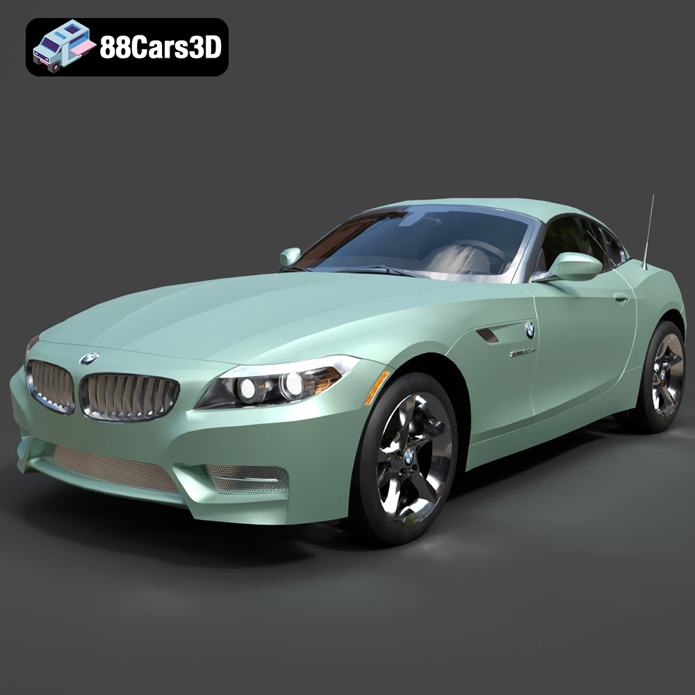
BMW Z4 Roadster E89 2012 3D Model
Texture: Yes
Material: Yes
Download the BMW Z4 Roadster E89 3D Model featuring clean geometry, realistic detailing, and a fully modeled interior. Includes .blend, .fbx, .obj, .glb, .stl, .ply, .unreal, and .max formats for rendering, simulation, and game development.
Price: $13.99

BMW Z4 E85 2005 3D Model
Texture: Yes
Material: Yes
Download the BMW Z4 E85 3D Model featuring clean geometry, realistic detailing, and a fully modeled interior. Includes .blend, .fbx, .obj, .glb, .stl, .ply, .unreal, and .max formats for rendering, simulation, and game development.
Price: $13.99

BMW M3 2024 3D Model
Texture: Yes
Material: Yes
Download the BMW M3 2024 3D Model featuring clean geometry, realistic detailing, and a fully modeled interior. Includes .blend, .fbx, .obj, .glb, .stl, .ply, .unreal, and .max formats for rendering, simulation, and game development.
Price: $13.99
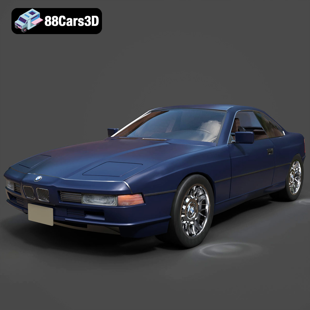
BMW 850i Coupe 1990 3D Model
Texture: Yes
Material: Yes
Download the BMW 850i Coupe 1990 3D Model featuring clean geometry, realistic detailing, and a fully modeled interior. Includes .blend, .fbx, .obj, .glb, .stl, .ply, .unreal, and .max formats for rendering, simulation, and game development.
Price: $13.99
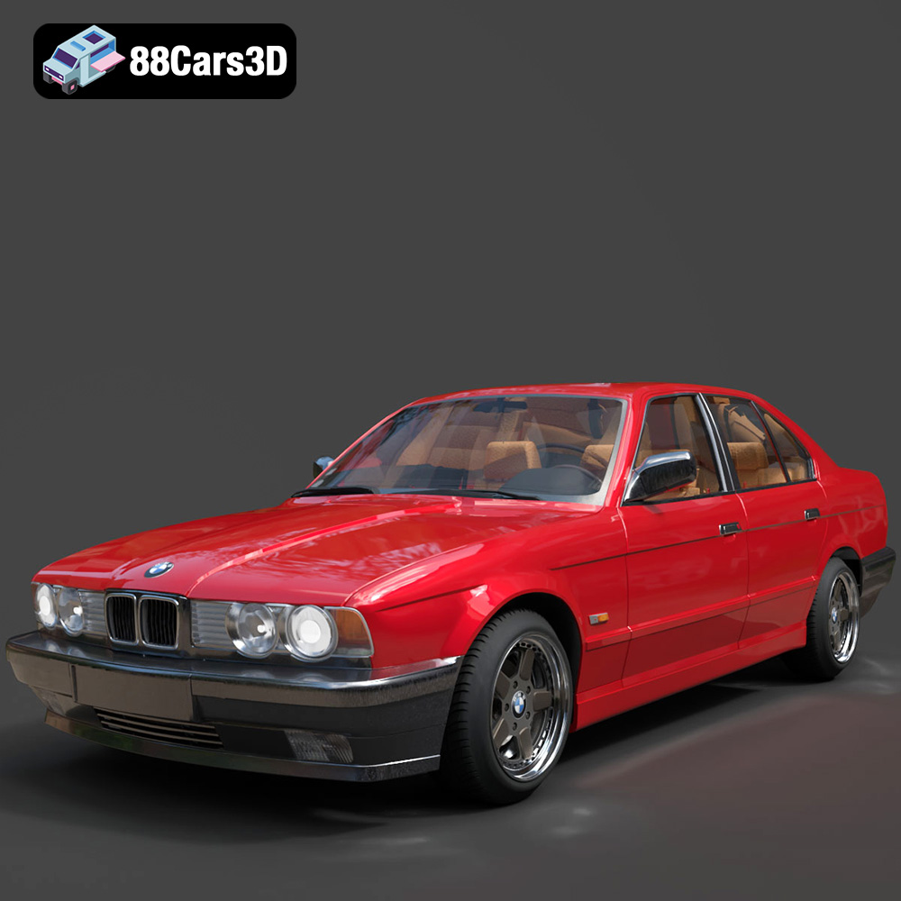
BMW 525i E34 1993 3D Model
Texture: Yes
Material: Yes
Download the BMW 525i E34 1993 3D Model featuring clean geometry, realistic detailing, and a fully modeled interior. Includes .blend, .fbx, .obj, .glb, .stl, .ply, .unreal, and .max formats for rendering, simulation, and game development.
Price: $12.99

BMW 7 Series 2016 3D Model
Texture: Yes
Material: Yes
Download the BMW 7 Series 2016 3D Model featuring luxurious design, detailed interior, and accurate exterior. Includes .blend, .fbx, .obj, .glb, .stl, .ply, .unreal, and .max formats for rendering, simulation, and game development.
Price: $10.79
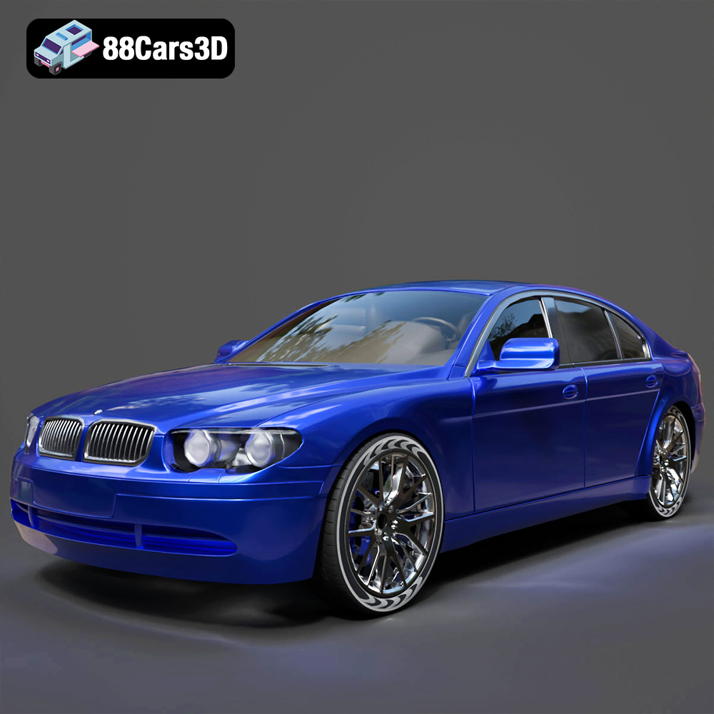
BMW 7 Series 30th Anniversary 3D Model
Texture: Yes
Material: Yes
Download the BMW 7 Series 30th Anniversary 3D Model featuring a meticulously crafted exterior, detailed interior, and realistic wheels. Includes .blend, .fbx, .obj, .glb, .stl, .ply, .unreal, and .max formats for rendering, simulation, and game development.
Price: $35.79

BMW 7-Series F02 3D Model
Texture: Yes
Material: Yes
Download the BMW 7-Series F02 3D Model featuring a detailed exterior and interior, optimized for rendering and animation. Includes .blend, .fbx, .obj, .glb, .stl, .ply, .unreal, and .max formats for rendering, simulation, and game development.
Price: $10.79
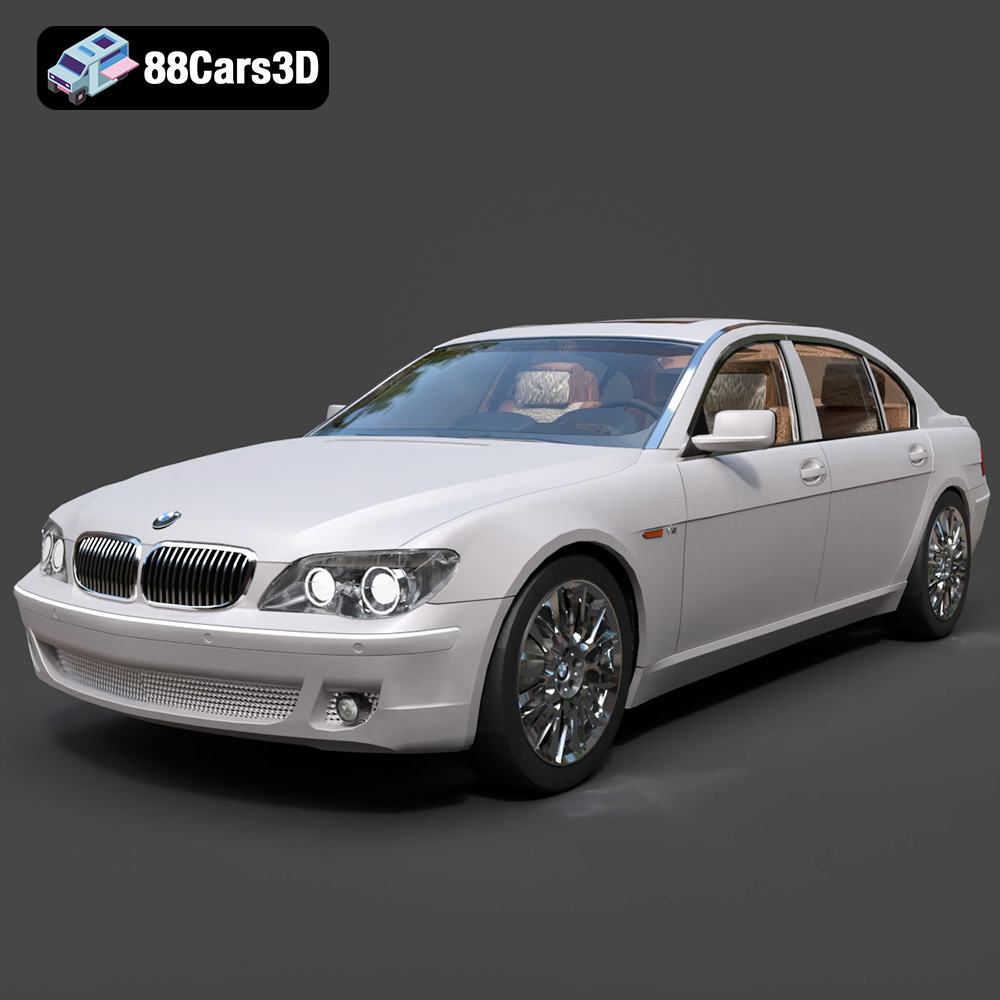
BMW 760Li E66 2005 3D Model
Texture: Yes
Material: Yes
Download the BMW 760Li E66 2005 3D Model featuring a detailed exterior, refined interior, and robust chassis. Includes .blend, .fbx, .obj, .glb, .stl, .ply, .unreal, and .max formats for rendering, simulation, and game development.
Price: $10.79
