
“`html
Mastering Your 3D Prints: Scaling, Hollowing, and Optimizing STL Files for Speed and Detail
The world of 3D printing is a fascinating intersection of digital design and physical creation. For enthusiasts and professionals alike, transforming a digital blueprint into a tangible object is an incredibly rewarding process. However, achieving high-quality prints, especially for intricate models like those found on 88cars3d.com, often requires more than just hitting the ‘print’ button. Understanding how to properly prepare your STL files—from scaling and hollowing to optimizing slicing parameters—is crucial for both print success and efficiency. This article will guide you through the essential techniques to scale, hollow, and optimize your printable car models for faster print times without sacrificing the exquisite detail that makes these digital replicas so desirable. We’ll delve into the technical nuances of STL file manipulation, slicing strategies, and printer settings, ensuring your next FDM or resin print is a triumph.
Understanding the Anatomy of an STL File
Before we dive into manipulation, it’s essential to grasp what an STL file fundamentally is. Standing for Stereolithography (or Standard Triangle Language), STL is the de facto standard for 3D printing data. It describes the surface geometry of a 3D object using a collection of triangular facets. Each facet is defined by three vertices (points in 3D space) and a normal vector, which indicates the outward direction from the surface. This simple yet powerful representation allows 3D printers to reconstruct the object layer by layer.
Mesh Topology and Manifold Integrity
The arrangement and connectivity of these triangles, known as mesh topology, significantly impact printability. A “manifold” mesh is one that forms a closed, watertight volume, meaning it has no holes, self-intersections, or flipped normals. Imagine a balloon: it’s a single, continuous surface. A non-manifold mesh is like a balloon with holes or patches overlapping incorrectly. Most slicing software struggles with non-manifold geometry, leading to errors like missing sections, incorrect infill, or print failures. Software like Meshmixer, Blender, or Netfabb are invaluable tools for diagnosing and repairing mesh issues. Common problems include:
- Holes: Gaps in the surface that need to be filled.
- Flipped Normals: Triangles facing inwards instead of outwards, confusing the slicer.
- Non-Manifold Edges: Edges shared by more than two triangles or edges that don’t connect properly.
- Internal Faces: Triangles inside the model’s volume that don’t form part of the external surface.
Identifying and fixing these issues is the first step towards a successful print, especially for complex models like detailed automotive replicas where a clean surface is paramount.
File Formats Beyond STL
While STL is ubiquitous, it’s worth noting other file formats used in 3D modeling and printing. OBJ (Object) files can store color and texture information alongside geometry, making them suitable for visual renders. FBX (Filmbox) is another versatile format often used in animation and game development, capable of storing complex scene data. However, for direct 3D printing, STL remains the most widely supported format. When downloading models from marketplaces such as 88cars3d.com, you’ll primarily encounter STL files, which are ready for direct use in your slicer after any necessary scaling or preparation.
Scaling Your Models: From Miniature to Museum Piece
One of the primary advantages of 3D printing is the ability to produce models at virtually any scale. Whether you want a tiny desktop trinket or a large-scale display piece, scaling is a fundamental operation. However, scaling isn’t just about resizing; it involves considering printer limitations, desired detail levels, and structural integrity.
Proportional vs. Non-Proportional Scaling
Most slicing software allows for proportional scaling, where all dimensions (X, Y, Z) are increased or decreased by the same factor, maintaining the original aspect ratio. This is ideal for general resizing. Non-proportional scaling allows you to adjust individual axes. This can be useful for correcting minor distortions or adapting a model to fit specific constraints, but it can also drastically alter the model’s intended proportions if not used carefully. For automotive models, maintaining the sleek lines and accurate dimensions is crucial, so proportional scaling is usually the preferred method.
Detail Considerations at Different Scales
As you scale a model down, fine details can become smaller than the printer’s capabilities (e.g., the nozzle diameter for FDM or the pixel size for resin printers). Small features like thin spoilers, intricate grilles, or emblems might disappear or print as blobs. Conversely, scaling up can sometimes reveal imperfections in the original mesh or lead to printing artifacts becoming more pronounced. When scaling, consider these points:
- Minimum Feature Size: Research your printer’s capabilities. For FDM, a nozzle size of 0.4mm typically means details smaller than 0.8-1.0mm in any dimension might struggle. For resin, the resolution is much higher, but extremely fine details can still be fragile.
- Structural Integrity: Scaling up thin parts can make them incredibly fragile. You might need to thicken walls or add internal supports during the design or preparation phase.
- Visual Accuracy: Ensure that scaling doesn’t compromise the iconic proportions of the vehicle.
For example, scaling a 1:24th scale model down to 1:72nd might render the side mirrors unprintable on an FDM printer unless they are intentionally thickened or designed to be printed separately.
Practical Scaling Workflow
Using your slicer (like Cura or PrusaSlicer):
- Import STL: Load your desired model file.
- Select Model: Ensure the model is selected.
- Access Scale Tool: Find the scaling options in the software’s toolbar or settings panel.
- Choose Uniform Scaling: Enter a single percentage value (e.g., 200% to double the size, 50% to halve it) or a scaling factor for all axes (X, Y, Z).
- Preview: Observe the model in the virtual build space to ensure proportions are maintained and details remain visible.
- Apply and Slice: Confirm the scaling and proceed to slicing.
For advanced manipulation or before slicing, software like Meshmixer or Blender offers more precise control over scaling and even allows for mesh repair or modification if scaling reveals issues with fine details.
Hollowing Models: Saving Material and Print Time
Many 3D printer settings for solid objects involve printing them completely filled with internal structure (infill). For larger or solid models, this can consume significant amounts of filament/resin and drastically increase print time. Hollowing the model—making it hollow with a specified wall thickness—is a common optimization technique to reduce material usage and speed up printing, particularly beneficial for FDM printing.
The Benefits of Hollowing
Hollowing offers several advantages:
- Reduced Material Consumption: Significantly less filament or resin is used, lowering costs.
- Faster Print Times: Less material means less extrusion or curing, leading to quicker prints. A hollowed model can print in a fraction of the time compared to a solid one.
- Reduced Weight: For large models, hollowing makes them lighter and easier to handle.
- Less Warping Potential: For materials like ABS that are prone to warping, solid large prints can experience significant internal stresses. Hollowing can alleviate some of these stresses.
However, hollowing is not always suitable. Extremely small models might not benefit much, and some resin printers might struggle with very thin internal walls during curing. For detailed printable car models, hollowing is often ideal for the main body while smaller components might remain solid.
Techniques for Hollowing
There are two primary ways to achieve a hollow model:
- Slicer-Based Hollowing: Most modern slicers (Cura, PrusaSlicer, Simplify3D) offer a “Hollow” or “Wall Thickness” setting. This feature automatically creates an internal cavity, leaving a specified wall thickness. It’s the simplest method but offers less control.
- CAD/Mesh Editing Software: Using tools like Meshmixer, Blender, or Fusion 360 provides more control. You can manually create an internal shell, add drainage holes (essential for resin printing to allow uncured resin to escape), and precisely define wall thickness. This is often the preferred method for complex models or when specific structural requirements exist.
For resin printing, hollowing is almost essential for larger models to prevent suction forces from damaging the print or the FEP film during layer separation, and to save expensive resin. Adding drainage holes is critical here; place them strategically in areas that won’t be visible or can be easily post-processed.
Setting Wall Thickness and Drainage Holes
When using slicer-based hollowing, a typical wall thickness might range from 1mm to 3mm for FDM, depending on the nozzle size and desired durability. For resin, 1mm to 2mm is common. If you’re manually hollowing:
- Select Model: Import the STL into your chosen software (e.g., Meshmixer).
- Use Offset/Hollow Tool: Apply an offset inwards to create the internal cavity. Specify the desired wall thickness.
- Add Drainage Holes (Resin): Use sculpting or primitive tools to create holes. Ensure they are large enough (at least 2-3mm diameter) and strategically placed. Consider adding two holes if the model has distinct internal chambers.
- Check for Errors: Ensure the hollowing process didn’t create non-manifold geometry or disconnect parts.
- Export Modified STL: Save the hollowed model.
Remember to check the slicer preview after hollowing to ensure the internal structure is as expected and that there are no unintended gaps.
Optimizing Slicing Parameters for Print Speed
The slicer is your bridge between a digital 3D model and the G-code instructions your 3D printer understands. Fine-tuning slicing parameters is key to balancing print speed, quality, and material efficiency. For intricate printable car models, achieving a balance is critical – you want speed, but not at the expense of crisp lines, smooth surfaces, and accurate details.
Layer Height: The Detail vs. Speed Tradeoff
Layer height is perhaps the most impactful setting on print time. It determines the thickness of each deposited layer of material.
- Lower Layer Heights (e.g., 0.08mm – 0.12mm): Result in finer detail, smoother curves, and less visible layer lines. Ideal for high-detail models but significantly increase print time.
- Higher Layer Heights (e.g., 0.2mm – 0.3mm): Faster print times, but layer lines become more pronounced, and fine details may be lost.
For FDM printing, a common baseline for good quality is 0.15mm or 0.2mm. If speed is a priority and some layer lines are acceptable, increasing to 0.24mm or 0.28mm can cut print times substantially. For resin printing, layer heights typically range from 0.025mm to 0.1mm, with lower values yielding superior surface finish but much longer prints.
Print Speed and Acceleration Settings
Beyond layer height, the actual speed at which the print head moves (print speed) and how quickly it changes speed (acceleration and jerk) play a huge role.
- Outer Wall Speed: This should generally be slower than the inner walls to ensure a smooth, clean exterior finish. Aim for 25-40 mm/s for good results.
- Inner Wall Speed: Can often be printed faster, perhaps 50-60 mm/s.
- Infill Speed: Typically the fastest, as infill is internal and imperfections are less visible (e.g., 60-80 mm/s).
- Travel Speed: The speed at which the nozzle moves when not extruding. Higher speeds (120-150 mm/s) reduce non-printing time but can increase stringing if retraction settings aren’t optimized.
- Acceleration & Jerk: These settings control how quickly the printer reaches its target speed and how much vibration is allowed. Higher acceleration/jerk can speed up prints but may introduce ringing artifacts if the printer frame is not rigid or calibrated well. Experimentation is key here, often starting with default profiles and incrementally increasing.
Many slicers have pre-set profiles like “Draft,” “Standard,” and “Fine.” Understanding these settings allows you to create custom profiles that prioritize speed when needed.
Infill Density and Patterns: The Hidden Structure
Infill provides internal support for the outer walls and top layers.
- Density: For decorative models, 10-15% infill is often sufficient. For functional parts or models requiring structural integrity, 20-50% might be necessary. Reducing infill density drastically cuts down on print time and material.
- Patterns: Different patterns (Grid, Lines, Gyroid, Cubic) offer varying strengths and print times. Gyroid is popular for its strength in all directions and relatively efficient printing. Grid and Lines are faster but less strong isotropically.
For a display car model, 10-15% infill with a Gyroid pattern usually provides an excellent balance of speed, material saving, and internal support.
Optimizing for Speed: A Practical Approach
- Start with a Baseline Quality Profile: Select a profile that offers acceptable quality (e.g., 0.2mm layer height).
- Enable Acceleration Control: If your slicer and printer firmware support it, enable acceleration and jerk settings.
- Increase Infill Speed: Set infill speed to 70-80 mm/s.
- Increase Travel Speed: Set travel speed to 120-150 mm/s, ensuring retraction is tuned to prevent stringing.
- Adjust Layer Height: If speed is still paramount, consider increasing layer height to 0.24mm or 0.28mm, but preview the results carefully.
- Reduce Infill Density: For non-structural models, try 10% or even 5% infill.
- Analyze Slicer Preview: Always use the layer-by-layer preview in your slicer to identify potential issues, estimate print time, and see how the speed optimizations affect the print path.
Remember that aggressive speed settings require a well-calibrated and rigid printer. A shaky frame or loose belts will lead to artifacts like ringing or ghosting at higher speeds.
Support Structures: The Unsung Heroes of Complex Prints
Intricate models, especially detailed car bodies with overhangs, spoilers, and undercuts, almost always require support structures. These temporary structures are printed alongside the model to hold up sections that would otherwise print in mid-air, preventing drooping or complete failure. Proper support generation and removal are critical for achieving clean, detailed prints.
When and Why to Use Supports
Supports are necessary when:
- A section of the model overhangs the layer below by more than a certain threshold (typically 45-60 degrees).
- There are significant bridges (horizontal sections spanning a gap).
- Fine or delicate features might collapse under their own weight during printing.
For printable car models from sites like 88cars3d.com, which are designed with printability in mind, supports might only be needed for specific overhangs. The designers often incorporate features like chamfered edges or split designs to minimize support requirements.
Types of Supports and Their Settings
Slicers offer various support types:
- Normal/Grid Supports: Basic structures that fill space under overhangs. Can be difficult to remove cleanly.
- Tree/Organic Supports: Branching structures that connect to the model at fewer points, making them easier to remove and often leaving cleaner contact points. Highly recommended for complex geometries.
- Support Towers/Rafts: Sometimes used as a base or to isolate delicate parts.
Key settings to optimize include:
- Support Overhang Angle: Set the minimum angle that requires support (e.g., 50 degrees).
- Support Density: Lower density (10-15%) makes removal easier.
- Support Interface Layers: Printing a denser pattern of layers just below the model can create a smoother surface where supports attach, aiding removal.
- Support Z Distance: The gap between the top of the support and the bottom of the model. A larger gap (e.g., 0.2mm for FDM) makes removal easier but can lead to a rougher surface finish on the model. Smaller gaps require more force to remove.
- Support XY Separation: The horizontal gap between the support and the model.
Experimentation is crucial. Too few supports lead to failure; too many or improperly configured supports can damage the model during removal or leave unsightly marks.
Support Removal Techniques
Patience and the right tools are key:
- Allow Cooling: Let the print cool completely before attempting removal. Brittle parts are less likely to break.
- Use Appropriate Tools: A hobby knife, pliers (needle-nose are excellent), dental picks, and sometimes small files are invaluable.
- Work Gently: Start by gently wiggling the support structure. If it’s a tree support, try breaking off the smaller branches first.
- Score and Pry: For stubborn supports, carefully score the interface point with a hobby knife before attempting to pry.
- Sand and File: After removal, use sandpaper (starting with coarse grit and moving to finer grits) or small files to smooth out any marks left by the supports.
- Acetone (for ABS): For ABS prints, a light wipe with acetone can sometimes smooth minor support marks, but use with extreme caution and ventilation.
For resin prints, supports are typically removed after washing and before the final curing. They snap off more cleanly but can still leave small nubs that require sanding.
Advanced Optimizations and Post-Processing
Beyond the fundamental steps of scaling, hollowing, and slicing optimization, several advanced techniques and post-processing steps can elevate your 3D printed car models from good to exceptional. These often involve material selection, printer calibration, and meticulous finishing.
Material Selection: PLA, PETG, ABS, and Resins
The choice of material significantly impacts the printability and final appearance:
- PLA: Easy to print, low warping, good detail. Ideal for display models. Available in many colors and finishes (wood, metal fill). Can be brittle.
- PETG: More durable and temperature resistant than PLA, but can be stringier and requires slightly higher temperatures. Good for functional parts or models needing more resilience.
- ABS: Strong, temperature resistant, can be smoothed with acetone. Requires an enclosed printer due to high temperatures and fumes, and is prone to warping.
- Resin (SLA/DLP/MSLA): Offers incredibly high detail and smooth surfaces, ideal for intricate car models. Requires more post-processing (washing, curing) and specific safety precautions (gloves, ventilation). Various types exist (Standard, Tough, Flexible, Castable).
For most printable car models intended for display, PLA or Standard Resins offer the best balance of ease of use and detail reproduction.
Printer Calibration and Maintenance
A well-calibrated printer is the foundation for successful prints. Key calibration steps include:
- Bed Leveling: Ensures the first layer adheres evenly across the build plate. Manual or automatic leveling systems are available.
- E-Step Calibration: Ensures the extruder pushes the correct amount of filament.
- Temperature Tower & Retraction Tests: Fine-tune printing temperatures and retraction settings for optimal extrusion and minimal stringing for your specific filament/resin.
- PID Tuning: Stabilizes nozzle and bed temperatures for consistent printing.
Regular maintenance, such as cleaning the nozzle, lubricating Z-axis rods, and ensuring belts are tensioned, prevents many common printing failures.
Post-Processing: The Finishing Touches
Once a print is complete and supports are removed, post-processing brings out the best in the model:
- Sanding: Start with a coarse grit (e.g., 120-220) to remove layer lines and support marks, gradually moving to finer grits (e.g., 400, 800, 1000+) for a smooth finish. Wet sanding can be effective.
- Filling: Use modeling putty, filler primer, or even epoxy putty to fill any remaining gaps or imperfections. Sand smooth after drying.
- Priming: A coat of primer helps reveal surface flaws and provides a uniform base for paint.
- Painting: Use acrylic model paints, airbrushing, or spray paints. Masking tape is essential for achieving clean lines between different colors (e.g., body, trim, windows).
- Assembly: For multi-part models, use appropriate adhesives (super glue/CA glue for most plastics, epoxy for stronger bonds).
- Clear Coating: A final clear coat (gloss, satin, or matte) protects the paint job and provides a finished look.
This meticulous finishing process is what transforms a raw 3D print into a professional-looking replica.
Conclusion: Your Blueprint for Print Success
Successfully 3D printing intricate models like those found on 88cars3d.com hinges on a deep understanding of the entire workflow, from file preparation to the final painted piece. By mastering the techniques of scaling your models to the desired size, hollowing them to conserve resources and time, and meticulously optimizing your slicing parameters, you can dramatically improve both the quality and efficiency of your prints. Remember that effective support generation and removal are crucial for capturing delicate details without damaging the print, and that careful material selection, printer calibration, and patient post-processing are the final steps that elevate a good print to a great one.
Don’t be afraid to experiment. Every printer, material, and model is slightly different. Utilize the preview functions in your slicer extensively, run calibration tests regularly, and learn from each print. Armed with this knowledge, you’re well-equipped to tackle even the most complex printable car models, turning digital designs into stunning physical realities. Happy printing!
“`
Featured 3D Car Models
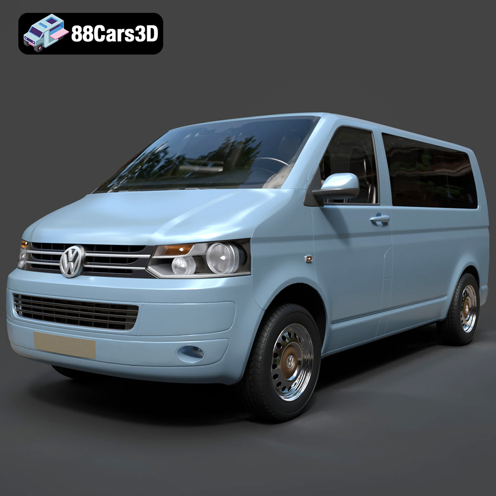
Volkswagen Transporter T5 FL 2010 3D Model
Texture: Yes
Material: Yes
Download the Volkswagen Transporter T5 FL 2010 3D Model featuring clean geometry, realistic detailing, and a fully modeled interior. Includes .blend, .fbx, .obj, .glb, .stl, .ply, .unreal, and .max formats for rendering, simulation, and game development.
Price: $22.99
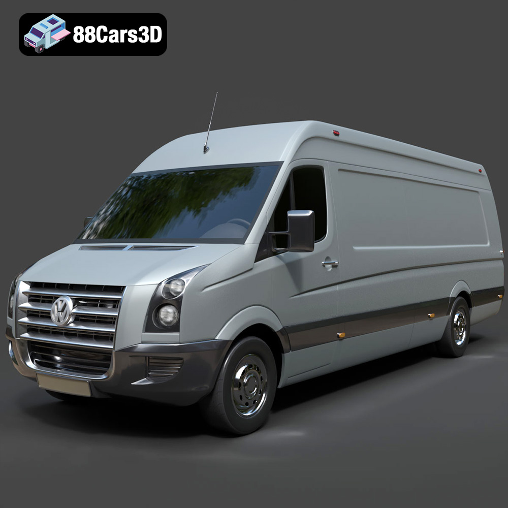
Volkswagen Crafter 2020 3D Model
Texture: Yes
Material: Yes
Download the Volkswagen Crafter 2020 3D Model featuring clean geometry, realistic detailing, and a fully modeled interior. Includes .blend, .fbx, .obj, .glb, .stl, .ply, .unreal, and .max formats for rendering, simulation, and game development.
Price: $22.99
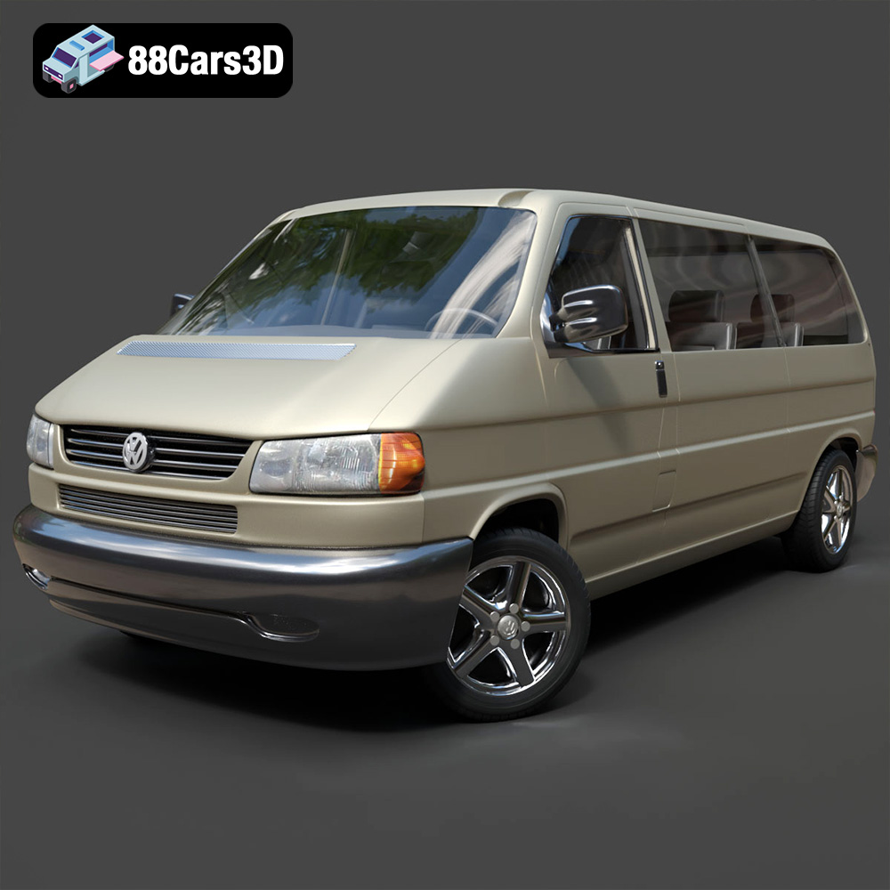
Volkswagen Caravelle 2020 3D Model
Texture: Yes
Material: Yes
Download the Volkswagen Caravelle 3D Model featuring a detailed exterior, functional interior, and optimized topology. Includes .blend, .fbx, .obj, .glb, .stl, .ply, .unreal, and .max formats for rendering, simulation, and game development.
Price: $23.99
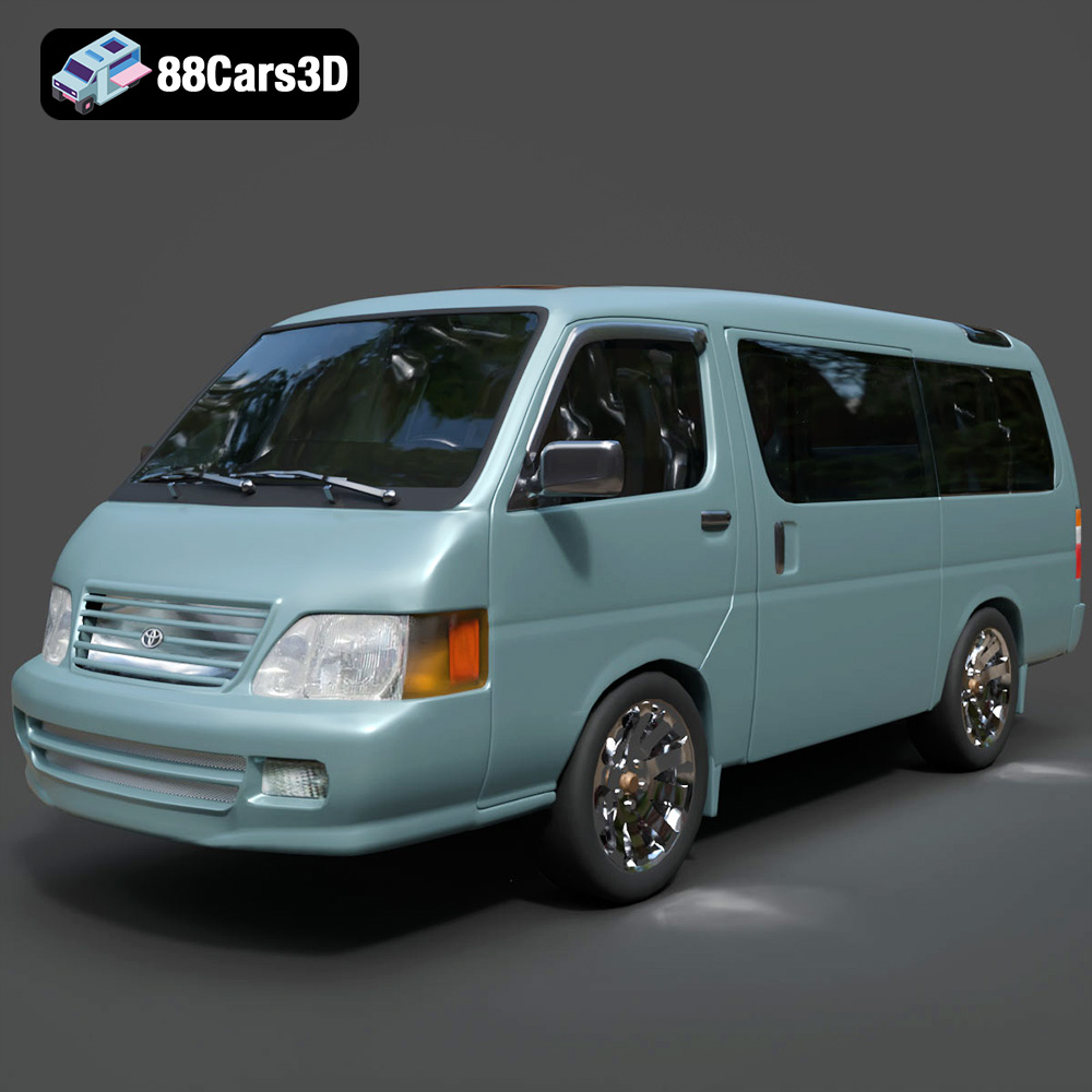
Toyota Hiace 3D Model
Texture: Yes
Material: Yes
Download the Toyota Hiace 3D Model featuring versatile design and detailed exterior. Includes .blend, .fbx, .obj, .glb, .stl, .ply, .unreal, and .max formats for rendering, simulation, and game development.
Price: $21.99
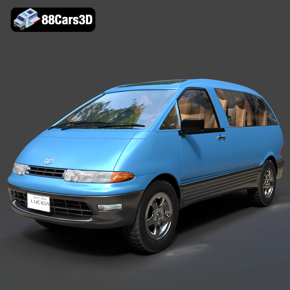
Toyota Estima Lucida 3D Model
Texture: Yes
Material: Yes
Download the Toyota Estima Lucida 3D Model featuring its iconic compact MPV design, versatile interior, and accurate exterior details. Includes .blend, .fbx, .obj, .glb, .stl, .ply, .unreal, and .max formats for rendering, simulation, and game development.
Price: $24.99

Toyota Alphard 3D Model
Texture: Yes
Material: Yes
Download the Toyota Alphard 3D Model featuring a detailed luxury minivan design with an accurate exterior and interior. Includes .blend, .fbx, .obj, .glb, .stl, .ply, .unreal, and .max formats for rendering, simulation, and game development.
Price: $21.99
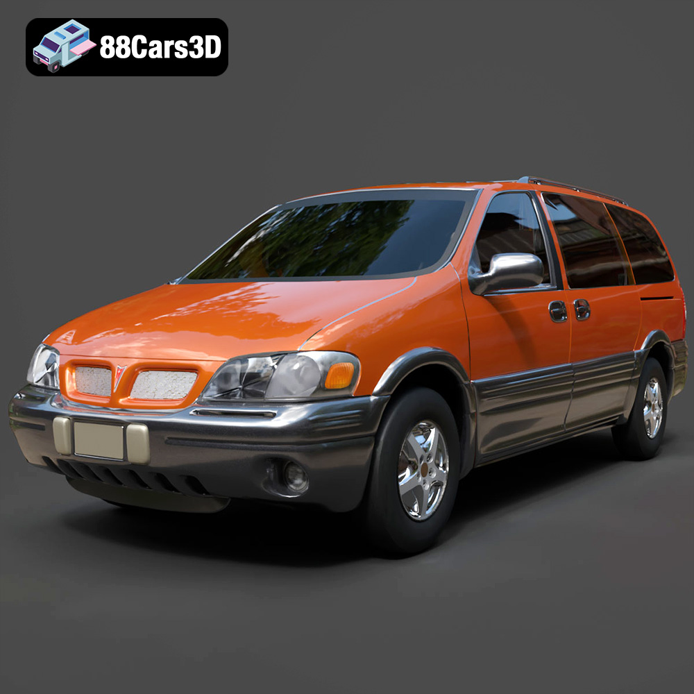
Pontiac Montana 1998 3D Model
Texture: Yes
Material: Yes
Download the Pontiac Montana 1998 3D Model featuring a detailed exterior, functional interior, and optimized mesh. Includes .blend, .fbx, .obj, .glb, .stl, .ply, .unreal, and .max formats for rendering, simulation, and game development.
Price: $21.99
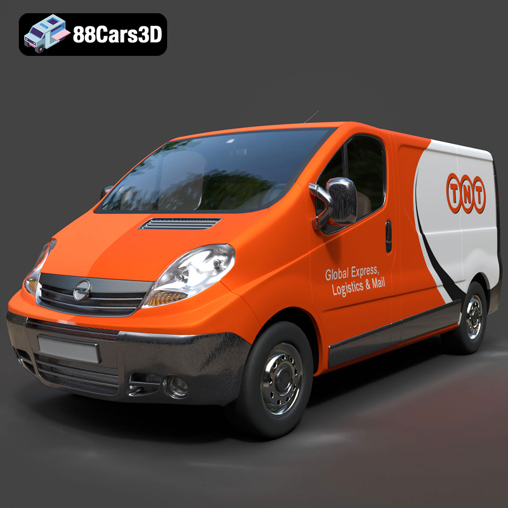
Opel Vivaro 3D Model
Texture: Yes
Material: Yes
Download the Opel Vivaro 3D Model featuring a versatile commercial van design with balanced detailing. Includes .blend, .fbx, .obj, .glb, .stl, .ply, .unreal, and .max formats for rendering, simulation, and game development.
Price: $21.99
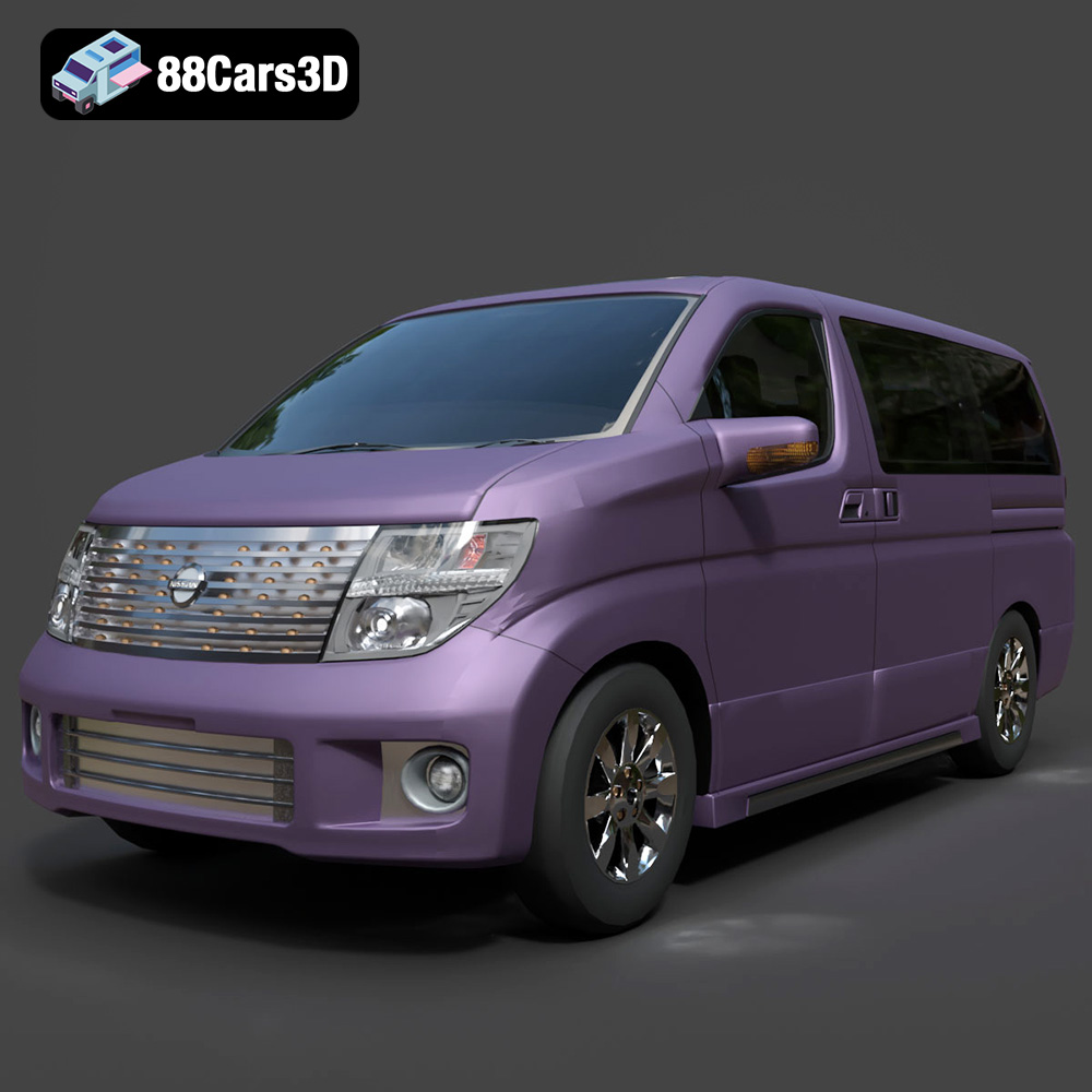
Nissan Elgrand 3D Model
Texture: Yes
Material: Yes
Download the Nissan Elgrand 3D Model featuring a versatile minivan design. Includes .blend, .fbx, .obj, .glb, .stl, .ply, .unreal, and .max formats for rendering, simulation, and game development.
Price: $21.99
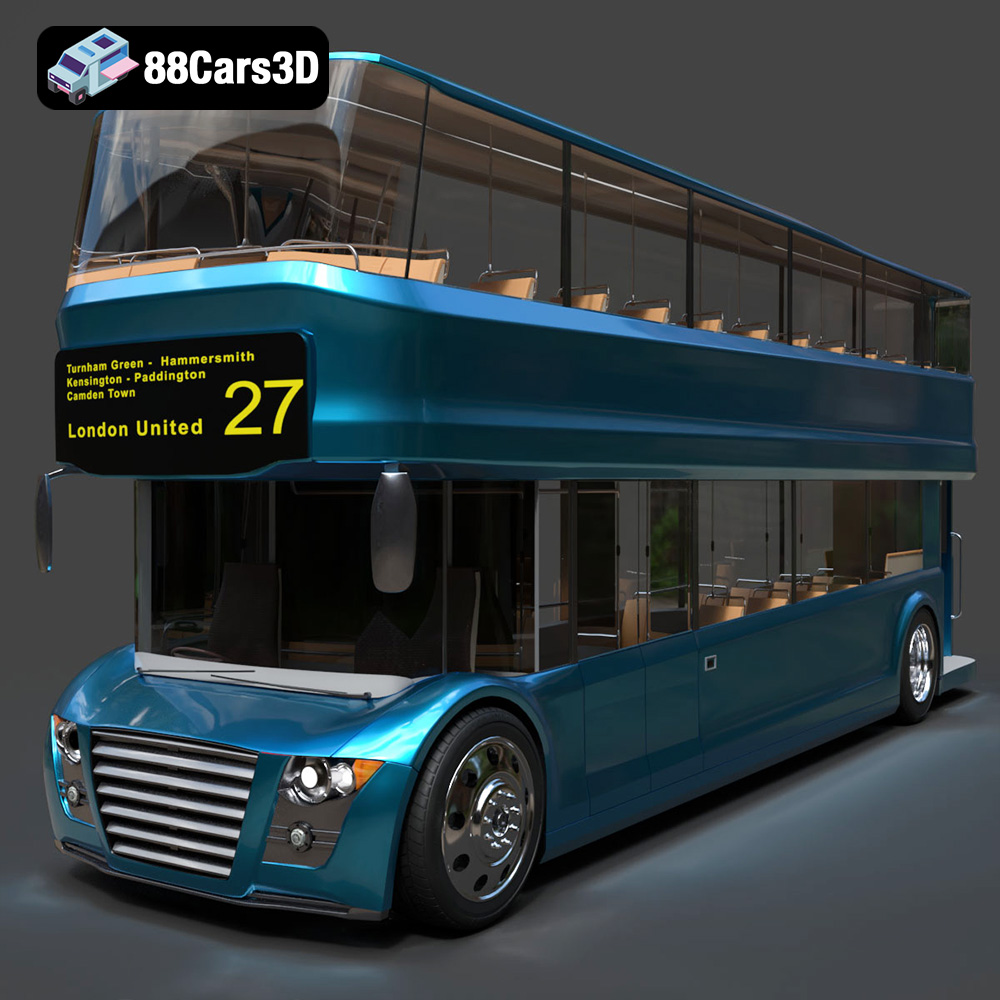
New Bus For London 3D Model
Texture: Yes
Material: Yes
Download the New Bus For London 3D Model featuring a detailed exterior and interior, optimized for rendering and animation. Includes .blend, .fbx, .obj, .glb, .stl, .ply, .unreal, and .max formats for rendering, simulation, and game development.
Price: $21.99
