In the high-stakes world of automotive design, visualization, and game development, realism is paramount. For enthusiasts and professionals alike, the allure of a finely crafted 3D car model lies in its ability to replicate every detail of its real-world counterpart. Among the most challenging yet rewarding materials to master in 3D is carbon fiber. Its distinct weave, anisotropic reflections, and deep, clear-coated sheen demand a sophisticated approach to material creation. A truly realistic carbon fiber material can elevate a good 3D model into an exceptional one, making it indistinguishable from a photograph.
This comprehensive guide delves deep into the technical intricacies of creating stunningly realistic carbon fiber materials for your 3D automotive models. Whether you’re a seasoned 3D artist, a game developer, or an automotive designer, mastering this material will significantly enhance the visual fidelity of your projects. We’ll explore everything from the fundamental physics of carbon fiber to advanced PBR workflows, software-specific shading techniques, optimal lighting setups, and game engine optimizations. By the end of this article, you’ll possess the knowledge and practical tips to render carbon fiber that not only looks authentic but also performs efficiently across various applications, from high-fidelity renders to real-time interactive experiences.
Understanding Carbon Fiber: The Science Behind the Sheen
Before we jump into the digital creation process, it’s crucial to understand what makes real-world carbon fiber look the way it does. Carbon fiber isn’t just a pattern; it’s a composite material made of thin, strong crystalline filaments of carbon atoms woven together and then encased in a resin, often epoxy. This construction dictates its unique visual properties, particularly its distinct reflectivity and depth. Ignoring these physical characteristics often leads to materials that look flat or artificial.
Microscopic Structure and Weave Patterns
The foundation of carbon fiber’s appearance is its weave. Carbon fiber fabrics come in several common patterns, each with a unique visual signature:
- Plain Weave: The simplest weave, where individual fibers cross over and under each other in an alternating pattern. It’s tight and stable but can be harder to form over complex curves.
- Twill Weave: The most common and visually recognizable, characterized by its diagonal pattern (e.g., 2×2 or 3×1 twill). This weave drapes easily and is excellent for complex shapes. The “2×2” signifies that each warp fiber goes over two weft fibers and under two weft fibers. This creates the characteristic diagonal rib.
- Satin/Harness Weave: Less common in visible applications, where fibers float over several other fibers before going under one. This creates a very smooth, lustrous surface but is less stable.
Understanding these patterns is vital because they directly influence how light interacts with the surface. The way the fibers interlace creates subtle undulations that catch and reflect light differently depending on the viewing angle, leading to the material’s iconic shimmer.
Anisotropy and Reflection Characteristics
Perhaps the most challenging aspect of carbon fiber to reproduce accurately is its anisotropic reflection. Anisotropy means that the material’s reflective properties vary depending on the direction of the light and the viewer. Instead of a circular highlight like a perfectly smooth, isotropic surface, carbon fiber exhibits elongated, directional reflections that follow the orientation of its interwoven fibers. This effect is most pronounced with twill weaves, where the diagonal lines of the weave create distinct stretches of highlights. This isn’t just a visual trick; it’s a direct consequence of light scattering along the length of the individual carbon filaments. Reproducing this accurately in a 3D shader requires careful manipulation of tangent space and often specialized anisotropic shading models.
Clear Coat Properties and Depth
Most aesthetic carbon fiber components, especially in automotive applications, are finished with a clear resin or lacquer coat. This clear coat adds significant depth, gloss, and protection. It acts as a separate layer on top of the woven carbon, introducing its own set of reflective properties. The interplay between the reflections off the clear coat and the underlying carbon weave is what gives the material its characteristic “wet” or “deep” look. Simulating this requires a layered material approach, where the clear coat’s Fresnel reflections and glossiness are accurately represented, allowing the underlying weave details to subtly show through.
PBR Workflow for Carbon Fiber Textures
The Physically Based Rendering (PBR) workflow is indispensable for achieving photorealistic materials like carbon fiber. PBR textures and shaders are designed to accurately simulate how light interacts with surfaces in the real world, leading to more consistent and believable results across various lighting conditions. For carbon fiber, this means meticulously crafting several texture maps that define its unique properties.
Essential PBR Maps
A typical PBR setup for carbon fiber will involve several key maps:
- Albedo/Base Color Map: This map defines the inherent color of the carbon fiber, which is typically a very dark gray to black. It should be desaturated and not contain any lighting information. Subtle color variations or reflections should be handled by other maps.
- Normal Map: This is critical for conveying the intricate weave pattern without requiring excessive polygon counts. A high-quality normal map will simulate the bumps and depressions of the interwoven fibers, making the surface appear complex even on a flat plane. It’s often generated from a high-resolution mesh or directly from a texture generator.
- Roughness Map: This map dictates how rough or smooth the surface is, influencing the sharpness and spread of reflections. For clear-coated carbon fiber, the overall roughness will be low, indicating a smooth, glossy finish. However, subtle variations in the clear coat, perhaps from minor imperfections or dust, can be introduced with slight roughness variations.
- Metallic Map: Carbon fiber itself is not metallic, but the clear coat sits on top of it. Therefore, this map will typically be black (0.0) or very close to it, indicating a dielectric material. If you’re simulating bare carbon fiber without a clear coat, it would still be dielectric.
- Ambient Occlusion (AO) Map: While not always strictly necessary for basic PBR, an AO map can add subtle self-shadowing in the crevices of the weave, enhancing depth and realism, especially for static renders.
Creating Weave Patterns: Procedural vs. Image-Based
The weave pattern is the visual heart of carbon fiber. You have two primary approaches for generating this:
- Image-Based Textures: This involves using high-resolution photographs of carbon fiber or meticulously crafted seamless textures. The advantage is immediate realism if the source is good. However, image-based textures can sometimes show tiling artifacts if not prepared correctly, and resolution can be a limitation for extreme close-ups. For optimal results, ensure your image textures are at least 4K (4096×4096 pixels) for a typical automotive panel to maintain crisp detail.
- Procedural Textures: This method involves mathematically generating the weave pattern within your 3D software’s shader editor. The biggest advantage is infinite resolution, perfect tiling, and complete control over every parameter (weave scale, fiber thickness, distortion, etc.). While more complex to set up, procedural carbon fiber can yield superior and more flexible results. Many artists combine both, using a procedural generator for the base weave and then overlaying subtle imperfections from image-based textures.
When creating a seamless tileable texture, pay close attention to the intersection points of the fibers. The diagonals must align perfectly across the edges of the texture to avoid visible seams.
Seamless Texturing and Tiling Strategies
For large surfaces or multiple parts on a car, seamless texturing is crucial. Visible seams instantly break the illusion of realism.
- UV Mapping: Ensure your 3D model has clean, non-overlapping UVs. For automotive panels, often a planar or box projection can work as a starting point, followed by manual adjustments to ensure the weave flows logically across the surface. Complex curved surfaces may require more sophisticated unfolding.
- Texture Resolution: Always use textures with sufficiently high resolution. For close-up shots or game assets intended for first-person views, 4K or even 8K textures might be necessary for large panels. For smaller, less prominent parts, 2K might suffice.
- Tiling Scale: The scale of the carbon fiber weave needs to be consistent across the entire vehicle. A common pitfall is having different weave scales on adjacent panels, which looks unnatural. Use a master material setup or shared texture coordinates to ensure uniformity.
Advanced Material Shading in 3D Software
Once you have your PBR textures, the next step is to assemble them into a sophisticated shader network within your chosen 3D software. This is where the magic of simulating anisotropy and clear coat depth truly happens. Each software has its own approach, but the underlying principles remain similar.
Node-Based Material Editors (Blender, 3ds Max, Maya)
Modern 3D applications rely heavily on node-based material editors, offering unparalleled flexibility and control.
- Blender (Cycles/Eevee): Blender’s shader editor is extremely powerful. You’ll typically start with a Principled BSDF shader as your base. To achieve anisotropy, you can directly control the “Anisotropic” and “Anisotropic Rotation” inputs. The Anisotropic Rotation input is crucial and usually driven by a tangent map or procedural texture that aligns with the weave direction. For a multi-layered material like carbon fiber with a clear coat, you might use a Mix Shader node to blend a glossy clear coat layer (another Principled BSDF or a dedicated Glossy BSDF) over your carbon fiber base, driven by a Fresnel input for realistic edge falloff.
- 3ds Max (V-Ray/Corona): In 3ds Max, using renderers like V-Ray or Corona offers dedicated material types or advanced shader nodes. V-Ray’s V-RayMtl and Corona’s CoronaMtl have built-in anisotropy controls. You’ll connect your normal map, roughness map, and albedo. For the clear coat, you can either layer a separate material using a Blend material or utilize the clear coat parameters available in the advanced material types, which often include separate controls for clear coat glossiness, IOR, and bump.
- Maya (Arnold/Redshift): Maya’s Hypershade editor works similarly. Arnold’s aiStandardSurface shader is versatile and includes robust anisotropy controls, typically using a tangent input for direction. Redshift’s RedshiftMaterial also offers anisotropic reflection options. Layering for the clear coat can be achieved using the “Coat” attributes directly within these shaders, allowing you to specify a separate coat color, roughness, and IOR.
Simulating Anisotropic Reflections (Tangent Space, UV Direction)
The key to realistic anisotropy is providing the shader with directional information. This is typically done through a tangent map or by deriving it from UV coordinates:
- Tangent Map: A tangent map (sometimes combined with the normal map or as a separate texture) tells the shader the direction of the surface’s “grain” at each point. For carbon fiber, this map would typically follow the diagonal flow of the weave. This is the most accurate method.
- UV Direction: Many shaders can derive tangent direction directly from the UV coordinates. By rotating the UVs in specific areas, you can influence the direction of the anisotropic reflections. This is often simpler but less precise than a dedicated tangent map.
Experiment with the “Anisotropic Rotation” parameter in your shader. For a 2×2 twill weave, the reflections often align at approximately 45 degrees relative to the main fiber direction, creating the characteristic ‘X’ shape in highlights.
Layering Clear Coat Shaders for Depth and Realism
A true clear coat is a dielectric layer sitting on top of the base material. To simulate this accurately:
- Create your base carbon fiber material with its dark color, normal map, and slight roughness.
- Create a separate glossy material for the clear coat, typically with a slightly lower IOR (around 1.4-1.5 for clear lacquer) and a very low roughness value to make it highly reflective. Its color should be white or very slightly tinted.
- Use a blend or mix shader to layer the clear coat over the base carbon fiber. The blending factor is often controlled by a Fresnel node, ensuring the clear coat’s reflections are most prominent at grazing angles, just like real-world clear coats.
This layered approach correctly simulates light interacting with two distinct surfaces, providing the visual depth and complex reflections that are the hallmark of high-quality carbon fiber.
Using Falloff Maps and Fresnel for Edge Definition
Falloff maps (like Fresnel) are essential for making materials appear volumetric and realistic. For carbon fiber:
- Fresnel Effect: This natural optical phenomenon makes surfaces more reflective when viewed at grazing angles (almost parallel to the surface). Incorporate a Fresnel node into your clear coat’s blend factor and potentially its roughness to control reflectivity based on viewing angle.
- Edge Wear/Chipping: While carbon fiber is robust, edges can show subtle signs of wear. Falloff maps, combined with procedural noise or edge detection nodes, can be used to introduce slight variations in roughness or color along sharp edges, adding to the realism.
Lighting and Rendering for Optimal Carbon Fiber Realism
Even the most perfectly crafted carbon fiber material will look flat and unconvincing under poor lighting. Lighting is critical to revealing the material’s complex reflections, anisotropy, and depth. A well-designed lighting setup will accentuate the weave and make the clear coat pop.
Importance of HDRI Environments and Studio Lighting
High Dynamic Range Image (HDRI) maps are invaluable for realistic automotive rendering.
- HDRI Environments: An HDRI acts as both a light source and a reflection map, providing realistic environmental lighting and complex reflections that bounce off the carbon fiber’s surface. Choose HDRIs with varied lighting information – a studio setup with softboxes, or an outdoor environment with a clear sky and direct sun, can both produce stunning results, each with a different mood.
- Studio Lighting Setups: For controlled, high-quality renders, augmenting HDRIs with traditional 3-point studio lighting (key, fill, rim lights) is highly effective. Softbox-like area lights are ideal for creating broad, even reflections that highlight the carbon fiber’s weave without harsh specular blowouts. Position lights to catch the diagonal weave pattern and reveal the anisotropy.
Key, Fill, and Rim Lighting for Surface Definition
A classic 3-point lighting setup is a great starting point:
- Key Light: The primary light source, typically positioned to illuminate the front and side of the car, defining the main shape and highlighting prominent carbon fiber panels. Its intensity and angle will largely dictate the overall look of the reflections.
- Fill Light: A softer, less intense light placed opposite the key light, used to soften shadows and reveal details in darker areas without flattening the image.
- Rim Light: A back light or side light that skims the edges of the car, creating a bright outline that separates the model from the background and emphasizes the contours of carbon fiber parts. This is particularly effective at highlighting the clear coat’s Fresnel effect.
When lighting carbon fiber, pay special attention to how the lights catch the weave. Subtle rotations of your area lights can dramatically change how the anisotropic reflections appear.
Render Engine Specifics (Corona, V-Ray, Cycles, Arnold)
Each render engine has its nuances, but all modern engines can handle complex materials:
- Corona Renderer: Known for its ease of use and physical accuracy, Corona excels at producing photorealistic results. Its interactive rendering allows for quick feedback when adjusting carbon fiber materials and lighting.
- V-Ray: A industry standard, V-Ray offers extensive controls for materials, lighting, and rendering. Its highly optimized physically based engine is perfect for production-quality automotive renders.
- Blender Cycles: Blender’s powerful path-tracing engine, Cycles, provides high-quality, unbiased rendering. It fully supports the Principled BSDF shader’s anisotropy and clear coat features, allowing for detailed carbon fiber shaders. Its GPU rendering capabilities make iterative adjustments relatively fast.
- Arnold: Autodesk’s flagship renderer, Arnold, is also a path-tracer, widely used in film and animation. Its robust shader system and physically accurate lighting make it ideal for high-end visualization of carbon fiber.
Optimizing Render Settings for Detail and Performance
Achieving realism often comes at the cost of render time. Optimize without sacrificing quality:
- Sampling/Bounces: For highly reflective materials like clear-coated carbon fiber, you’ll need sufficient reflection samples/bounces to accurately capture indirect reflections. Don’t go excessively high, but ensure enough bounces (e.g., 4-8) to capture the interplay of light.
- Noise Threshold: Balance render time with acceptable noise levels. For final renders, a very low noise threshold (e.g., 0.005) is desirable, while for previews, you can be more forgiving.
- Denoising: Utilize built-in denoisers (like NVIDIA OptiX or OpenImageDenoise in Blender) during post-processing to clean up noise and reduce render times without compromising detail.
Game Engine Integration and Optimization
Bringing realistic carbon fiber into real-time game engines like Unity or Unreal Engine requires a different set of considerations, focusing heavily on performance while maintaining visual fidelity. The goal is to achieve believable results within strict rendering budgets.
LODs (Level of Detail) for Performance
For complex 3D car models, especially those with intricate carbon fiber components, Level of Detail (LOD) systems are essential.
- Multiple Mesh Versions: Create several versions of your carbon fiber components, each with a progressively lower polygon count. The highest LOD (LOD0) will use the full-detail mesh and textures for close-up views.
- Texture Downscaling: As the distance from the camera increases, switch to lower-resolution textures for the carbon fiber. For instance, LOD0 might use 4K textures, LOD1 2K, and LOD2 1K or even procedural tiling for distant objects.
- Shader Complexity: Simplify the carbon fiber shader for lower LODs. You might remove some of the more expensive calculations for anisotropy or complex clear coat layering when the object is far away, as these subtle details won’t be noticeable.
Implementing an effective LOD strategy ensures that your carbon fiber looks great when it needs to, without bogging down the game engine’s performance.
Baking Textures for Real-time Environments
Unlike offline renderers that calculate light interactions dynamically, game engines often rely on pre-computed (baked) lighting and detail to achieve performance.
- Normal Map Baking: For the intricate weave pattern, baking a high-polygon carbon fiber mesh’s detail onto a low-polygon mesh’s normal map is a standard practice. This gives the illusion of high geometric detail with minimal performance cost.
- Ambient Occlusion Baking: Baking an AO map helps define crevices and adds depth, crucial for carbon fiber’s appearance, especially if real-time global illumination is limited.
- Reflection Probes: Game engines use reflection probes to capture the environment’s reflections and apply them to reflective surfaces like clear-coated carbon fiber. Strategically place these probes to accurately represent the surrounding environment.
Shader Optimization in Unity and Unreal Engine
Game engine shaders need to be lean and efficient.
- Unity (URP/HDRP): When working with Unity’s Universal Render Pipeline (URP) or High-Definition Render Pipeline (HDRP), you’ll use their respective PBR shaders. HDRP offers more advanced material features, including robust clear coat layering and anisotropic controls. For URP, you might need to implement a custom shader graph for true anisotropy or use workarounds. Keep shader instructions to a minimum.
- Unreal Engine: Unreal Engine’s powerful material editor (based on nodes) is well-suited for creating complex carbon fiber. You can leverage its clear coat shading model and anisotropic controls directly. Use material functions to encapsulate common carbon fiber logic and reuse it across multiple assets, reducing compilation time and improving consistency. Ensure your texture sample count is optimized.
Consider using a custom Unreal Engine Shading Model if the built-in PBR models don’t provide the exact anisotropic or clear coat properties you need, though this is an advanced topic.
AR/VR Considerations for Carbon Fiber Materials
AR/VR applications demand even higher performance optimization due to real-time rendering on mobile or specialized hardware, often with strict frame rate targets.
- Aggressive LODs: More aggressive LODs and texture streaming are critical.
- Simplified Shaders: Simplify your carbon fiber shaders even further. You might rely more on normal maps and less on complex layered clear coats to save on pixel shader operations.
- Baked Reflections: Fully baked reflection maps or very low-resolution reflection probes are often preferred over real-time reflections for performance.
- Scale and Perspective: Consider that carbon fiber’s intricate weave may not be visible or impactful in certain AR/VR scales or viewing distances, so balance detail with performance needs.
Post-Processing and Fine-Tuning
The rendering process doesn’t end when the image finishes calculating. Post-processing is a vital stage where you can enhance realism, correct imperfections, and give your carbon fiber renders a final polish, bringing them to life.
Enhancing Reflections and Specular Highlights
While your material and lighting setup should provide a strong foundation, post-processing can subtly boost reflections and highlights.
- Exposure and Contrast: Adjust these to make the carbon fiber pop. Increasing contrast slightly can deepen the blacks of the carbon and brighten the reflections.
- Levels/Curves: Fine-tune the tonal range to ensure the reflections aren’t blown out and the shadows aren’t crushed, preserving detail in both bright and dark areas.
- Bloom/Glow: Judiciously applying a subtle bloom effect to the brightest reflections can mimic real-world camera lens effects and enhance the sense of luminosity on the clear coat. Avoid overdoing it, as it can quickly look artificial.
Color Grading and Tonal Adjustments
Color grading can set the mood and integrate your carbon fiber asset into the broader scene.
- Color Balance: Adjust the overall color temperature and tint to match the scene’s aesthetic or to correct any color shifts from the rendering process.
- Saturation: Carbon fiber is inherently desaturated, but you can subtly adjust the overall saturation to enhance the visual impact of the surrounding colors without affecting the material itself too much.
- Vignetting: A subtle vignette can draw the viewer’s eye towards the center of the image, where the carbon fiber is typically most prominent.
Adding Subtle Imperfections (Dust, Scratches)
Perfect surfaces rarely exist in the real world. Introducing subtle imperfections adds a layer of realism that makes the material more believable.
- Fingerprints/Smudges: Overlaying very subtle, low-opacity grunge textures (connected to roughness or clear coat tint) can simulate fingerprints or smudges on the clear coat.
- Micro-scratches: Tiny, anisotropic scratches that follow a general direction can be added via a very fine normal map or by subtly influencing the roughness map. These are almost invisible but catch highlights in a way that suggests a real-world clear coat.
- Dust/Dirt: For a less pristine look, procedural or image-based dust layers can be blended in, typically affecting the roughness and albedo slightly.
These imperfections should be extremely subtle; the goal is to enhance realism, not to make the carbon fiber look damaged unless that’s the desired aesthetic. Platforms like 88cars3d.com often provide models with pristine materials, leaving such artistic decisions to the end user.
Final Output for Portfolio or Integration
Once your post-processing is complete, consider the final output format and resolution.
- Resolution: Render at high resolutions (e.g., 4K or 8K) for portfolio pieces or large prints to showcase the intricate details of your carbon fiber. For web or game integration, ensure resolutions are optimized.
- File Format: Save your final images in appropriate formats. PNG for lossless quality with transparency, or JPEG for web use with adjustable compression. For animations, consider codecs like H.264 or ProRes.
Conclusion
Creating truly realistic carbon fiber in 3D is a nuanced journey that combines a deep understanding of the material’s physical properties with advanced technical skills in 3D modeling, texturing, shading, and lighting. From meticulously crafting anisotropic reflections and layered clear coats to optimizing shaders for real-time engines, every step contributes to the final illusion of authenticity. We’ve explored the importance of weave patterns, the power of PBR workflows, software-specific shader implementations, and the critical role of thoughtful lighting.
The ability to render carbon fiber with stunning realism not only elevates your 3D automotive models but also demonstrates a mastery of complex material science in a digital context. Whether you’re aiming for a photorealistic showcase render or a high-performance game asset, the principles and techniques outlined in this guide provide a robust framework. Remember to always study real-world references, experiment with your tools, and fine-tune every parameter. By applying these detailed workflows, you’ll be well on your way to producing breathtaking carbon fiber materials that captivate your audience and meet the highest industry standards. For your next project, consider sourcing high-quality base models from marketplaces such as 88cars3d.com, then apply your newfound carbon fiber expertise to bring them to life with unparalleled realism.
Featured 3D Car Models

Meta Description:
Texture: Yes
Material: Yes
Download the Porsche Cayenne 3D Model featuring realistic exterior styling and detailed interior design. Includes .blend, .fbx, .obj, .glb, .stl, .ply, .unreal, and .max formats for rendering, simulation, AR VR, and game development.
Price: $19.9
View Product
Texture: Yes
Material: Yes
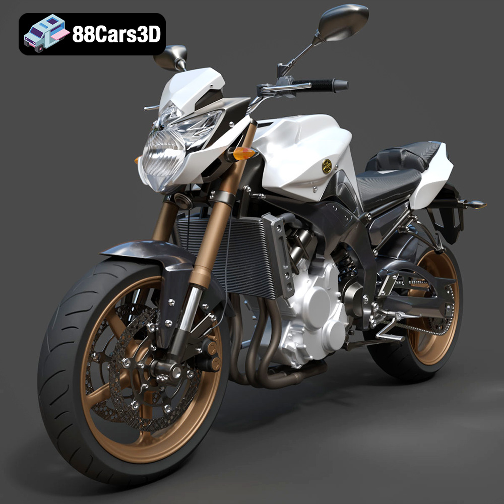
Download the Yamaha FZ8 2011 3D Model featuring clean geometry, realistic detailing, and a fully modeled interior. Includes .blend, .fbx, .obj, .glb, .stl, .ply, .unreal, and .max formats for rendering, simulation, and game development.
Price: $19.99
View Product
Texture: Yes
Material: Yes
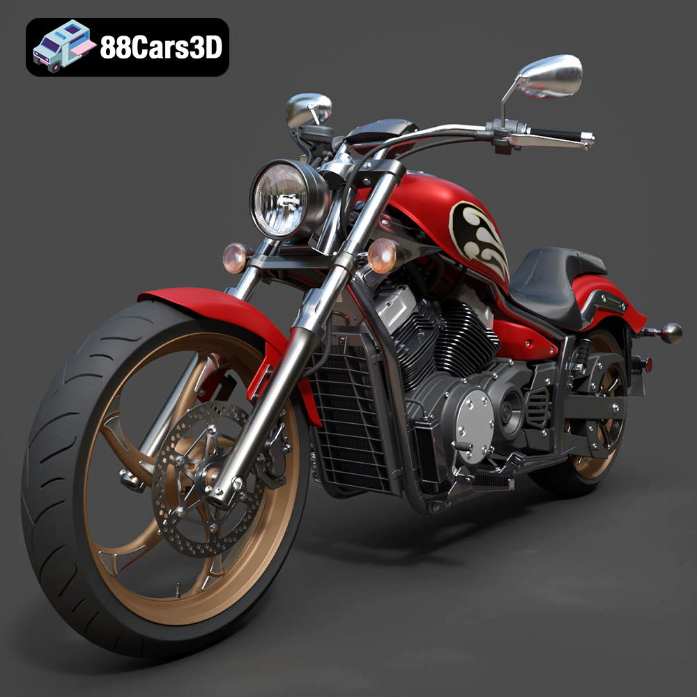
Download the Yamaha Stryker 2012 3D Model featuring clean geometry, realistic detailing, and a fully modeled interior. Includes .blend, .fbx, .obj, .glb, .stl, .ply, .unreal, and .max formats for rendering, simulation, and game development.
Price: $19.99
View Product
Texture: Yes
Material: Yes
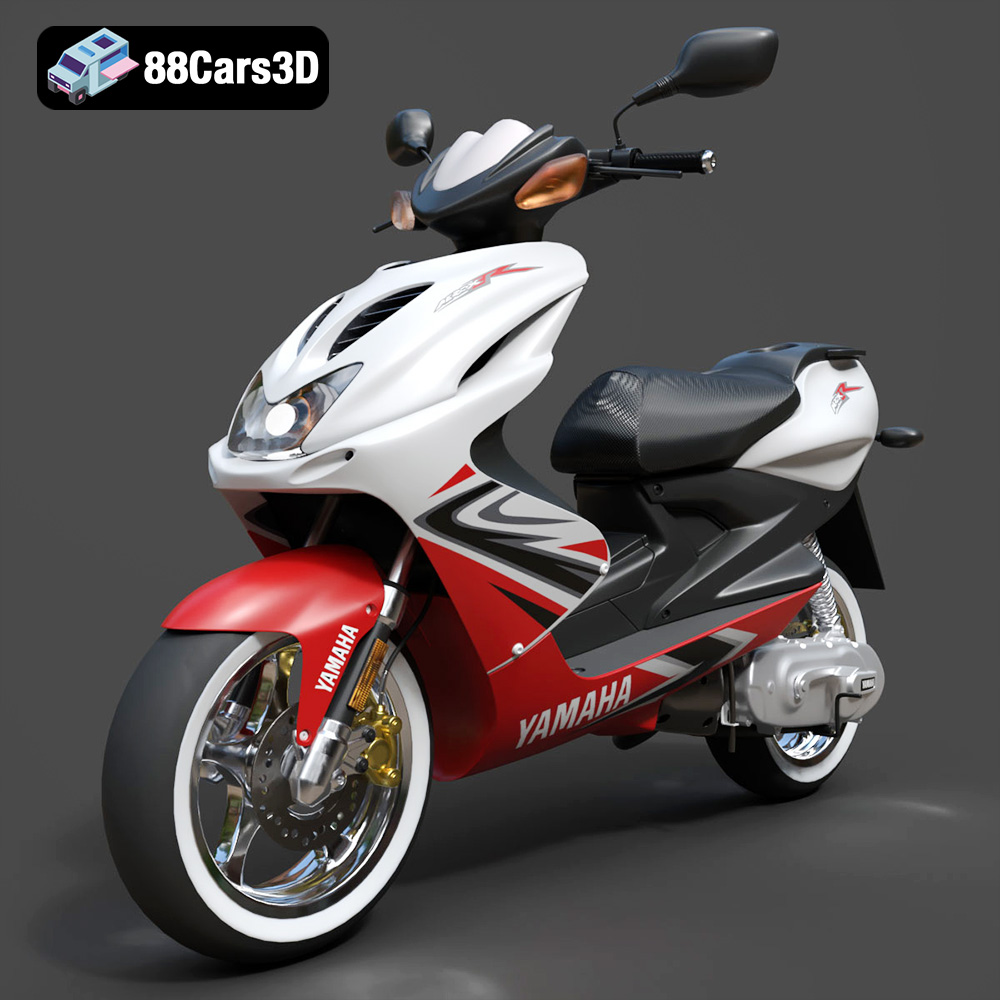
Download the Yamaha Aerox R-002 2024 3D Model featuring clean geometry, realistic detailing, and a fully modeled interior. Includes .blend, .fbx, .obj, .glb, .stl, .ply, .unreal, and .max formats for rendering, simulation, and game development.
Price: $19.99
View Product
Texture: Yes
Material: Yes
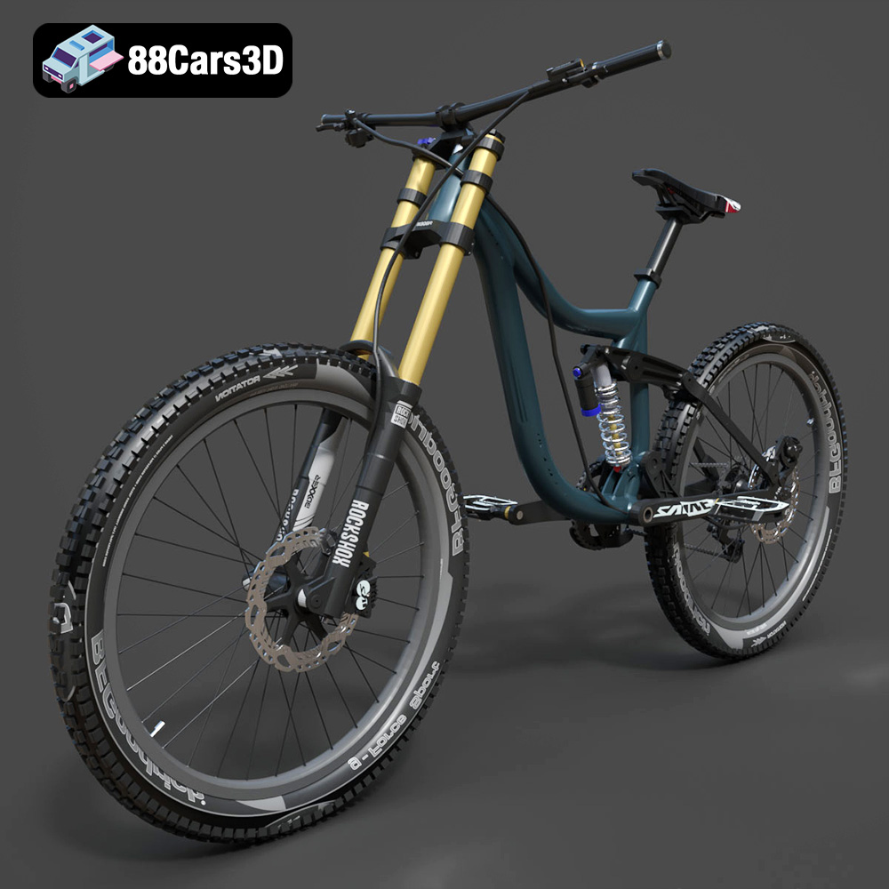
Download the Mototsikly Downhill Bike-002 3D Model featuring clean geometry, realistic detailing, and precise mechanical components. Includes .blend, .fbx, .obj, .glb, .stl, .ply, .unreal, and .max formats for rendering, simulation, and game development.
Price: $19.99
View Product
Texture: Yes
Material: Yes
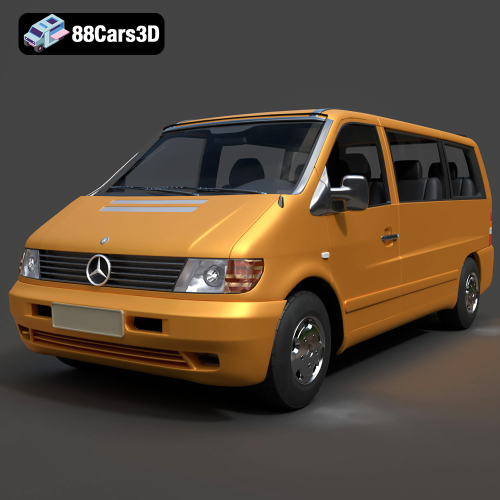
Download the Mercedes-Benz Vito Passenger Van 3D Model featuring clean geometry, realistic detailing, and a fully modeled interior. Includes .blend, .fbx, .obj, .glb, .stl, .ply, .unreal, and .max formats for rendering, simulation, and game development.
Price: $19.99
View Product
Texture: Yes
Material: Yes
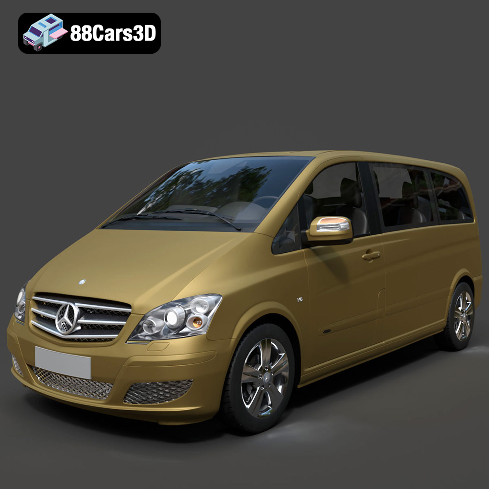
Download the Mercedes-Benz Viano 2010 3D Model featuring clean geometry, realistic detailing, and a fully modeled interior. Includes .blend, .fbx, .obj, .glb, .stl, .ply, .unreal, and .max formats for rendering, simulation, and game development.
Price: $19.99
View Product

Texture: Yes
Material: Yes
Download the Emt Avtobus 007 3D Model featuring clean geometry, realistic detailing, and a fully modeled interior. Includes .blend, .fbx, .obj, .glb, .stl, .ply, .unreal, and .max formats for rendering, simulation, and game development.
Price: $19.99
View Product
Texture: Yes
Material: Yes
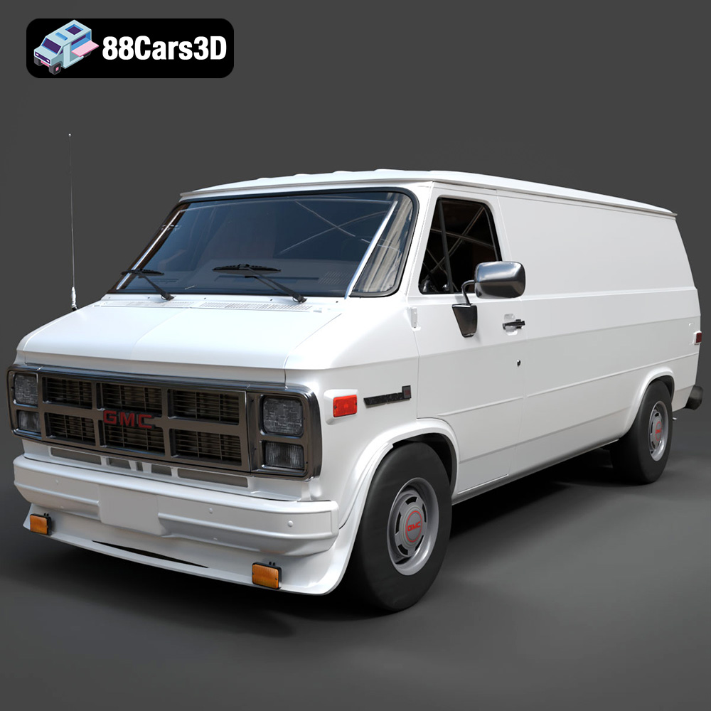
Download the GMC Vandura G-1500 1983 3D Model featuring clean geometry, realistic detailing, and a fully modeled interior. Includes .blend, .fbx, .obj, .glb, .stl, .ply, .unreal, and .max formats for rendering, simulation, and game development.
Price: $19.99
View Product
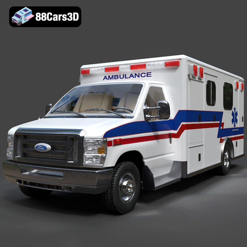
Texture: Yes
Material: Yes
Download the Ford E-450 Ambulance 3D Model featuring clean geometry, realistic detailing, and a fully modeled interior. Includes .blend, .fbx, .obj, .glb, .stl, .ply, .unreal, and .max formats for rendering, simulation, and game development.
Price: $19.99
View Product