
In the dynamic world of real-time rendering and automotive visualization, static images, no matter how photorealistic, often fall short of delivering truly immersive and interactive experiences. Modern users, from game players to professional automotive designers, expect dynamism. This is where Unreal Engine’s powerful Animation Blueprint system steps in, transforming high-quality 3D car models into vibrant, interactive assets. Far beyond simple character locomotion, Animation Blueprints provide the sophisticated control needed to articulate every moving part of a vehicle, from the subtle nuances of suspension travel to the complex sequences of an opening door, or even the interactive elements of a dashboard.
For studios and individual artists looking to push the boundaries of automotive realism, understanding Animation Blueprints is indispensable. Whether you’re building a cutting-edge car configurator, developing a next-gen racing game, or creating an interactive AR/VR training simulation, animating vehicle components is key to authenticity and engagement. This comprehensive guide will delve into the essentials of Unreal Engine Animation Blueprints, specifically tailored for automotive applications. We’ll explore the underlying principles, practical workflows, and advanced techniques to breathe life into your vehicle models, ensuring they not only look stunning but also respond dynamically to user input and environmental forces.
Preparing Your Automotive 3D Models for Animation in Unreal Engine
Before diving into the intricacies of Animation Blueprints, the foundational step is ensuring your 3D car models are properly prepared. Unlike static meshes, animated models require a skeletal hierarchy to dictate how their various components move. This process, often referred to as rigging, is crucial for creating articulate and controllable automotive assets within Unreal Engine. A well-structured skeletal mesh is the backbone of any successful automotive animation.
When sourcing 3D car models, platforms like 88cars3d.com often provide models pre-optimized for Unreal Engine, which can significantly streamline this process. However, understanding the underlying principles allows for greater control and troubleshooting. Your 3D application (e.g., Maya, Blender, 3ds Max) is where this initial rigging takes place. The goal is to create a logical bone hierarchy that mirrors the car’s physical moving parts. For instance, a root bone will typically govern the entire vehicle, with child bones for each door, the hood, trunk, wheels, and steering wheel. Each of these child bones will act as the pivot point for its corresponding mesh component.
Skeletal Mesh Requirements and Rigging Principles
The core principle for automotive rigging is to create a bone for every part you intend to animate. For a car, this typically includes:
- Root Bone: The parent of all other bones, controlling the overall position and orientation of the car.
- Chassis Bone: Often a direct child of the root, representing the main body.
- Wheel Bones: One for each wheel, typically positioned at the center of the wheel’s rotation axis. These will also have child bones for brake calipers (if static) or additional elements like suspension arms.
- Door Bones: One for each door, placed at the hinge point.
- Hood/Trunk Bones: Placed at their respective hinge points.
- Steering Wheel Bone: Centered for rotation.
- Interior Elements: Separate bones for dashboard needles, infotainment screens, wipers, etc.
Ensure that the pivot points (bone locations) accurately reflect the real-world hinge or rotation points of the car’s components. Proper naming conventions (e.g., Wheel_FL, Door_Driver, SteeringWheel) are essential for readability and easier referencing within Unreal Engine. Once rigged, the mesh and its skeleton are typically exported as an FBX file. During export, ensure that only the skeletal mesh option is selected, not static mesh, and that the “Embed Media” option is checked to include textures.
Importing and Verifying Your Skeletal Mesh in Unreal Engine
Upon importing your FBX file into Unreal Engine, you’ll be presented with various import options. For skeletal meshes, key settings include:
- Skeletal Mesh: Checked.
- Import Animations: Typically unchecked if you’re building animations within an Animation Blueprint, though you can import placeholder animations if needed.
- Physics Asset: Unreal can generate a basic Physics Asset, which is useful for collision and some physics interactions.
- Material Import Method: Choose ‘Create New Materials’ or ‘Do Not Create Materials’ if you plan to assign PBR materials manually or use existing ones, as often found with high-quality assets from 88cars3d.com.
Once imported, open the Skeletal Mesh Editor. Here, you can visually inspect the skeleton hierarchy in the ‘Skeleton Tree’ panel. Verify that all bones are present, correctly oriented, and parented as intended. You can also preview the mesh and its materials. This verification step is critical; any issues with the skeletal setup will propagate and complicate subsequent animation work in the Animation Blueprint. Refer to the official Unreal Engine documentation on Skeletal Mesh Import Pipeline for detailed guidelines.
Fundamentals of Animation Blueprints for Vehicles
The Animation Blueprint is the central hub for driving all skeletal mesh animation logic in Unreal Engine. It’s a specialized Blueprint class designed to interpret game state, input, and other variables, translating them into dynamic poses and movements for your skeletal mesh. For automotive applications, this means connecting variables like steering input, door open/close states, or suspension compression values directly to bone rotations and translations.
To create an Animation Blueprint, right-click in the Content Browser, navigate to Animation, and select “Animation Blueprint.” You’ll be prompted to choose the skeletal mesh it will control – select your car’s skeletal mesh. This will generate a new asset ready for editing. The Animation Blueprint editor is divided into two primary graphs: the Event Graph and the Anim Graph.
The Event Graph: Data Flow and Logic for Car Animations
The Event Graph in an Animation Blueprint functions similarly to a regular Blueprint’s Event Graph, handling logic and data flow. It’s where you define how external variables or game events will influence your car’s animations. Key events often used here include:
- Event Blueprint Update Animation: This event fires every frame and is the primary point to fetch variables and perform calculations that will drive your animations.
- Event Blueprint Initialize Animation: Used for one-time setup or initial variable assignments.
Within the Event Graph, you’ll typically cast to your vehicle’s main Blueprint (e.g., your custom car Blueprint class) to access its properties. For instance, you might retrieve a “CurrentSteeringAngle” float, a “DoorOpenState_FL” boolean, or a “SuspensionCompression_FR” float. These retrieved variables are then stored as local variables within the Animation Blueprint, ready to be used in the Anim Graph to directly manipulate bone transforms. This communication pipeline is fundamental to creating reactive and interactive vehicle animations. For more details on communication, see the Unreal Engine documentation on Blueprint Communication.
The Anim Graph: Structuring Your Vehicle’s Pose Updates
The Anim Graph is where the magic happens, visually representing the pose generation and blending logic. Unlike character Animation Blueprints that heavily rely on State Machines and Blend Spaces for locomotion, automotive Animation Blueprints often use a more direct approach for component animations:
- Local Space Transforms (Bone): This node allows you to directly manipulate the rotation, translation, or scale of a specific bone. For example, you can connect your “CurrentSteeringAngle” variable to the Z-axis rotation of the “SteeringWheel” bone.
- Blend Poses by Boolean: Useful for switching between two poses (e.g., door closed vs. door open) based on a boolean variable.
- Blend Poses by Float: Excellent for blending between multiple poses or interpolating a single pose based on a float value, perfect for smooth door opening or suspension travel.
- Layered Blend Per Bone: Allows you to apply animations or pose modifications to specific parts of the skeleton without affecting others. For example, animating only the wheels while the chassis remains static.
The final output of the Anim Graph connects to the “Final Animation Pose” node. This node consolidates all the pose manipulations, blending, and calculations into the ultimate pose that will be applied to your skeletal mesh each frame. Structuring this graph efficiently is crucial for performance, especially with many animated components. Begin with the primary chassis pose, then layer specific component animations on top using nodes like “Local Space Transforms (Bone)” or “Layered Blend Per Bone.”
Animating Car Components: Practical Applications
With the foundational understanding of Animation Blueprints, we can now explore practical applications for animating various car components. This is where your automotive models truly come alive, offering interactive possibilities for configurators, games, and realistic visualizations. The key is to map external inputs or internal physics data to specific bone manipulations within the Anim Graph.
Interactive Doors and Panels: Timelines and Blend Poses
Animating opening and closing car doors, hoods, or trunks is a common requirement for interactive automotive experiences. Instead of a simple snap, a smooth, timed animation is desired.
- Blueprint Variable: In your vehicle’s main Blueprint, create a boolean variable, e.g.,
bDriverDoorOpen. - Animation Blueprint Event Graph: Cast to your vehicle Blueprint to get the value of
bDriverDoorOpenand store it as a local variable in the AnimBP. - Animation Blueprint Anim Graph:
- Create a Blend Poses by Float node.
- Connect a Timeline node from the Event Graph to the ‘Alpha’ input of the Blend Poses by Float. The Timeline should have a float track interpolating from 0 to 1 over a short duration (e.g., 1-2 seconds).
- When
bDriverDoorOpenbecomes true, play the Timeline forward. When false, play it in reverse. - For Pose A (Alpha 0), use a default pose. For Pose B (Alpha 1), use a Local Space Transforms (Bone) node. Select the ‘Door_Driver’ bone and apply the desired rotation (e.g., -60 degrees on the Y-axis) for the open state.
- Ensure the rotation is in local space relative to the bone’s pivot.
This setup allows you to smoothly interpolate the door’s rotation based on the Timeline’s progress, triggered by your game logic. You can use separate Timelines for different doors or a single Timeline feeding multiple bone rotations for synchronized movements.
Dynamic Steering and Wheel Rotation: Syncing with Vehicle Physics
For realistic driving experiences, the steering wheel and individual wheels must dynamically respond to player input and vehicle physics.
- Vehicle Blueprint Data: If using Unreal Engine’s built-in Chaos Vehicles or a custom physics system, extract relevant data:
GetSteeringInput: Provides the current steering input (-1.0 to 1.0).GetWheelRotationSpeed: For each wheel, provides angular velocity.
Store these in the Animation Blueprint’s Event Graph as local variables (e.g.,
SteeringInput,WheelRotSpeed_FL). - Steering Wheel Animation (Anim Graph):
- Use a Local Space Transforms (Bone) node for the ‘SteeringWheel’ bone.
- Map the
SteeringInputvariable to a rotational range. For instance, multiplySteeringInputby a factor (e.g., 360 degrees for a full turn left/right) and apply it to the Z-axis rotation. - Add interpolation (e.g., a ‘Lerp’ node or ‘RInterpTo’ node) for smoother steering wheel rotation.
- Wheel Rotation Animation (Anim Graph):
- For each wheel bone (e.g., ‘Wheel_FL’), use a Local Space Transforms (Bone) node.
- Calculate the wheel’s rotation based on its angular velocity and the delta time. For a wheel rotating around its X-axis:
CurrentRotationX = CurrentRotationX + (WheelRotSpeed_FL * DeltaSeconds * RotationFactor). TheRotationFactorconverts angular velocity into degrees per second. - Apply this calculated rotation to the X-axis of the respective wheel bone.
This method ensures that your visual wheels and steering wheel accurately reflect the underlying physics simulation, providing a highly convincing driving experience.
Simulating Realistic Suspension Travel
Suspension compression and extension add significant realism, particularly when traversing uneven terrain or cornering. This requires per-wheel data from the vehicle’s physics system.
- Vehicle Blueprint Data: Access data about each wheel’s suspension compression. With Chaos Vehicles, you can get the
Suspension Compressionfor each wheel from the ‘Wheel’ nodes. This will typically be a normalized float (0.0 to 1.0 or similar). Store these in the AnimBP. - Suspension Animation (Anim Graph):
- For each wheel (or a dedicated suspension bone if your rig supports it), use a Local Space Transforms (Bone) node.
- Map the
Suspension Compressionvariable to a vertical translation (Z-axis, or local Y/Z depending on bone orientation) of the wheel bone or a dedicated suspension arm bone. - For instance,
Suspension_Z_Offset = Lerp(MinSuspensionTravel, MaxSuspensionTravel, SuspensionCompression_FL). Apply this Z-offset to the wheel bone’s local translation. - You can also apply slight rotations to connected suspension arms or brake calipers to visually represent their movement.
This approach brings dynamic visual feedback to the vehicle’s interaction with the ground, enhancing the sense of weight and motion.
Advanced Animation Blueprint Techniques for Automotive Visualization
Beyond basic component articulation, Animation Blueprints can be leveraged for highly sophisticated interactive experiences, such as full-fledged vehicle configurators or detailed virtual production scenarios. Integrating UI, data, and complex logic expands the utility of your animated car models.
Integrating with Vehicle Configurators and UI
Automotive configurators are a prime example of where Animation Blueprints shine. Users expect to interact with a car, opening doors, changing wheel types, or previewing different paint finishes.
- Material Swapping: While not directly an Animation Blueprint function, the AnimBP can work in conjunction with the main vehicle Blueprint to drive material changes. For instance, a UI button triggers an event in the vehicle Blueprint that sets a new material instance for specific mesh sections.
- Component Visibility/Swapping: For elements like spoilers, body kits, or different wheel designs, these are typically separate static or skeletal meshes. Your main vehicle Blueprint would handle swapping these meshes via a
Set Static MeshorSet Skeletal Meshnode on a component. However, if the swapped component *also* needs animation (e.g., a different type of door), its Animation Blueprint can be changed dynamically usingSet Anim Instance Classnode on the skeletal mesh component. - Driven Animation Variables: UI sliders or buttons can directly modify variables in your vehicle’s Blueprint, which are then passed to the Animation Blueprint. For example, a slider controlling “DoorOpenAmount” (0-1) can directly drive the ‘Alpha’ input of the door animation’s Blend Poses by Float node, giving the user granular control over how much the door opens.
This tight integration between UI, game logic, and Animation Blueprints allows for rich, interactive configuration experiences. For assets with multiple customization options, like those found on 88cars3d.com, this workflow is invaluable.
Customizing Dashboard Animations and Interactive Elements
Modern car interiors are replete with digital displays, animated gauges, and interactive buttons. Animation Blueprints are perfectly suited for bringing these elements to life.
- Gauge Needles: For analog gauges (speedometer, tachometer), create separate bones for each needle. In the Anim Graph, use Local Space Transforms (Bone) nodes. Map vehicle data (e.g., current speed, RPM) to a specific rotational range for each needle bone. Use ‘Lerp’ or ‘RInterpTo’ nodes for smooth, realistic needle movement, avoiding jarring jumps.
- Digital Displays: While the display content itself might be handled by UMG widgets rendered to a texture (using a Widget Component on a static mesh plane), the frame or animated elements around the screen can be bone-driven. For example, a folding screen mechanism could be animated with a Timeline and Blend Poses by Float, similar to doors.
- Button Presses: Create small bones for interactive buttons. When a button is pressed (via raycast or interaction component), use a Timeline to briefly translate the button bone inward, then back out, mimicking a physical press.
This level of detail significantly enhances the immersive quality of automotive visualizations, especially for close-up interior shots or VR experiences.
Optimizing Animation Performance for Automotive Scenes
While visual fidelity is paramount, maintaining optimal performance in real-time applications is equally critical, particularly for complex automotive scenes with many animated parts. Animation Blueprints, while powerful, can be computationally intensive if not managed properly.
- Animation Update Rates: In the ‘Class Defaults’ of your Animation Blueprint, you can adjust the ‘Update Rate’ and ‘Culling’ settings.
- Update Rate: For distant cars or non-critical animations, reduce the ‘Update Rate’ (e.g., update every 2nd or 4th frame).
- Culling: Enable ‘Use Bounds Culling’ to pause animation updates when the skeletal mesh is off-screen.
- Animation LODs (Level of Detail): Similar to mesh LODs, you can define Animation LODs. This allows simpler Animation Blueprints or even static poses to be used when the car is far from the camera. You can configure this in the Skeletal Mesh Editor under ‘LOD Settings’. Ensure less computationally expensive logic is used for lower LODs.
- Avoid Unnecessary Calculations: In the Event Graph, only calculate variables that have changed or are actively needed. Use ‘Do Once’ nodes for setup, and branch logic to skip calculations if a component isn’t active (e.g., don’t calculate door animation if doors are closed).
- Efficient Blend Logic: Prefer ‘Layered Blend Per Bone’ over full ‘Blend Poses’ when only a small section of the skeleton needs modification. Avoid overly complex state machines if simple direct bone manipulation suffices for the specific automotive component.
These optimization strategies are essential for maintaining high frame rates, especially in game development and AR/VR applications where performance budgets are tight.
Performance Optimization and Best Practices
Achieving realistic and interactive automotive experiences in Unreal Engine demands a careful balance between visual fidelity and real-time performance. Effective optimization of Animation Blueprints is paramount, particularly when dealing with high-polygon car models and complex scene environments.
Animation LODs and Culling for Automotive Scenes
Just as static meshes benefit from Level of Detail (LODs), skeletal meshes and their associated Animation Blueprints can be optimized through this system. Animation LODs allow you to reduce the complexity of the animation calculations based on the mesh’s distance from the camera.
- Skeletal Mesh Editor Setup: In your Skeletal Mesh Editor, configure LODs for the mesh. For each LOD, you can specify different settings for triangle count, bone count, and even what Animation Blueprint to use.
- Reduced Bone Influence: For lower LODs, consider simplifying the skeleton by removing or ignoring bones that won’t be visible at a distance (e.g., individual dashboard buttons, subtle suspension components). Unreal Engine provides options to reduce bone count per LOD.
- Animation Blueprint Optimization: Within your Animation Blueprint, you can check the current LOD level of the skeletal mesh using nodes like
Get Current LOD. This allows you to conditionally disable expensive animation logic for lower LODs. For instance, you might disable individual wheel rotation calculations for a car seen from afar, opting for a simple static pose or a more generalized rotation. - Culling Techniques:
- Bounds Culling: Enable ‘Use Bounds Culling’ in the Animation Blueprint’s Class Defaults. This will prevent the Animation Blueprint from updating when the skeletal mesh’s bounding box is outside the camera’s frustum.
- Component-Specific Culling: For very specific components, you might implement custom logic in the Event Graph to pause updates if a component’s visibility or interaction relevance is low (e.g., disabling interior animations when the car doors are closed).
Strategic use of LODs and culling ensures that processing power is allocated where it matters most, focusing detail on vehicles close to the player or camera.
Efficient Blueprint Logic and Variable Management
The efficiency of your Animation Blueprint logic directly impacts performance. Every node and calculation consumes resources, and repeated or unnecessary operations can quickly add up.
- Minimize Event Graph Calculations:
- Only perform expensive calculations once per frame if possible. The
Event Blueprint Update Animationnode runs every frame, so be mindful of what you place here. - Cache references to other Blueprints (e.g., your vehicle’s main Blueprint) using
Try Get Pawn Ownerand casting, storing the result in a local variable, rather than casting every frame. - Use
Do Oncenodes for initialization logic that only needs to run at the start.
- Only perform expensive calculations once per frame if possible. The
- Optimize Anim Graph Nodes:
- Use
Layered Blend Per Bonewhen only a subset of bones needs to be animated. This is more efficient than blending entire poses if only, for example, the doors or wheels are moving. - Avoid excessive nesting of complex blend nodes. Try to keep the Anim Graph as flat and direct as possible while maintaining desired complexity.
- Use direct bone manipulation nodes (
Local Space Transforms (Bone)) when precise control over individual bone rotations/translations is needed, rather than trying to achieve it through complex state machines or blend spaces which are often overkill for simple component movements.
- Use
- Variable Types: Use the most appropriate variable type. While less impactful than logic, using floats for values that require precision and booleans for simple on/off states is good practice.
Clean, concise, and logically structured Animation Blueprints are easier to debug and inherently more performant.
Real-World Application: AR/VR and Game Development Considerations
The optimization considerations for automotive Animation Blueprints become even more critical in specialized real-time applications like AR/VR and competitive game development.
- AR/VR Performance Budgets: Virtual and Augmented Reality experiences demand very high and consistent frame rates (e.g., 90 FPS or more per eye) to prevent motion sickness. This means aggressive optimization is necessary.
- Keep bone counts as low as possible for critical meshes.
- Limit the number of simultaneously animated components.
- Prioritize animations critical to interaction (e.g., doors) over subtle background animations (e.g., tiny dashboard lights).
- Consider baking complex animations into pre-recorded sequences for distant or less interactive elements to reduce real-time AnimBP overhead.
- Game Development: In game development, especially for multiplayer racing games or open-world environments, you might have many vehicles on screen simultaneously, each with its own Animation Blueprint.
- Implement server-side or network-aware animation updates to reduce bandwidth for replicated animations.
- Dynamically disable Animation Blueprints for vehicles outside a certain relevance distance, using simpler static poses or even fully despawning distant cars.
- Utilize Unreal Engine’s Anim Instance Pooling to reuse Animation Blueprint instances, reducing memory overhead for multiple identical vehicles.
- Virtual Production & LED Walls: For high-fidelity virtual production environments, performance is often less about frame rate for user interaction and more about rendering quality at a stable frame interval for film cameras. However, complex animations can still strain rendering resources. Focus on clean rigging, efficient AnimBP logic, and ensuring that any real-time data input is robust and synchronized.
By keeping these specific application contexts in mind, developers can tailor their Animation Blueprint strategies to meet the unique performance demands of their projects, ensuring a smooth and immersive experience for the end-user.
Conclusion: Driving Innovation with Animated Automotive Experiences
Animation Blueprints in Unreal Engine are an incredibly powerful tool, transforming static 3D car models into engaging, interactive, and visually stunning automotive experiences. From meticulously animating every door and panel to dynamically syncing steering wheels with vehicle physics and creating responsive dashboard elements, the possibilities are vast. We’ve explored the critical steps, from preparing your skeletal meshes and understanding the core components of the Animation Blueprint—the Event Graph and Anim Graph—to implementing practical animations for various car parts.
Furthermore, we delved into advanced techniques, demonstrating how Animation Blueprints are integral to sophisticated vehicle configurators and realistic interior interactions. Crucially, we highlighted the importance of performance optimization through Animation LODs, efficient Blueprint logic, and strategic culling, ensuring that your high-fidelity automotive visualizations run smoothly across diverse platforms, including demanding AR/VR and game development scenarios. The journey from a raw 3D model to a fully interactive vehicle is a testament to the power of Unreal Engine’s real-time capabilities.
By mastering these Animation Blueprint essentials, you unlock a new dimension of realism and interactivity for your automotive projects. Whether you are developing a next-generation game, a professional visualization, or an immersive AR/VR experience, the ability to breathe dynamic life into your car models is a significant advantage. Begin your journey today by exploring the vast library of high-quality, Unreal Engine-ready 3D car models available on platforms like 88cars3d.com, providing the perfect foundation for your animated automotive masterpieces. The road to truly immersive automotive visualization is animated, and with Unreal Engine’s Animation Blueprints, you’re in the driver’s seat.
Featured 3D Car Models

Porsche Cayenne 3D Model
Meta Description:
Texture: Yes
Material: Yes
Download the Porsche Cayenne 3D Model featuring realistic exterior styling and detailed interior design. Includes .blend, .fbx, .obj, .glb, .stl, .ply, .unreal, and .max formats for rendering, simulation, AR VR, and game development.
Price: $19.9
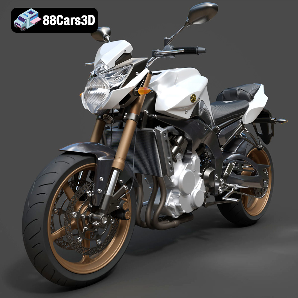
Yamaha FZ8 2011 3D Model
Texture: Yes
Material: Yes
Download the Yamaha FZ8 2011 3D Model featuring clean geometry, realistic detailing, and a fully modeled interior. Includes .blend, .fbx, .obj, .glb, .stl, .ply, .unreal, and .max formats for rendering, simulation, and game development.
Price: $19.99
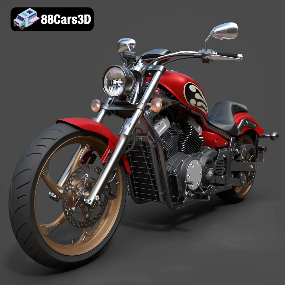
Yamaha Stryker 2012 3D Model
Texture: Yes
Material: Yes
Download the Yamaha Stryker 2012 3D Model featuring clean geometry, realistic detailing, and a fully modeled interior. Includes .blend, .fbx, .obj, .glb, .stl, .ply, .unreal, and .max formats for rendering, simulation, and game development.
Price: $19.99
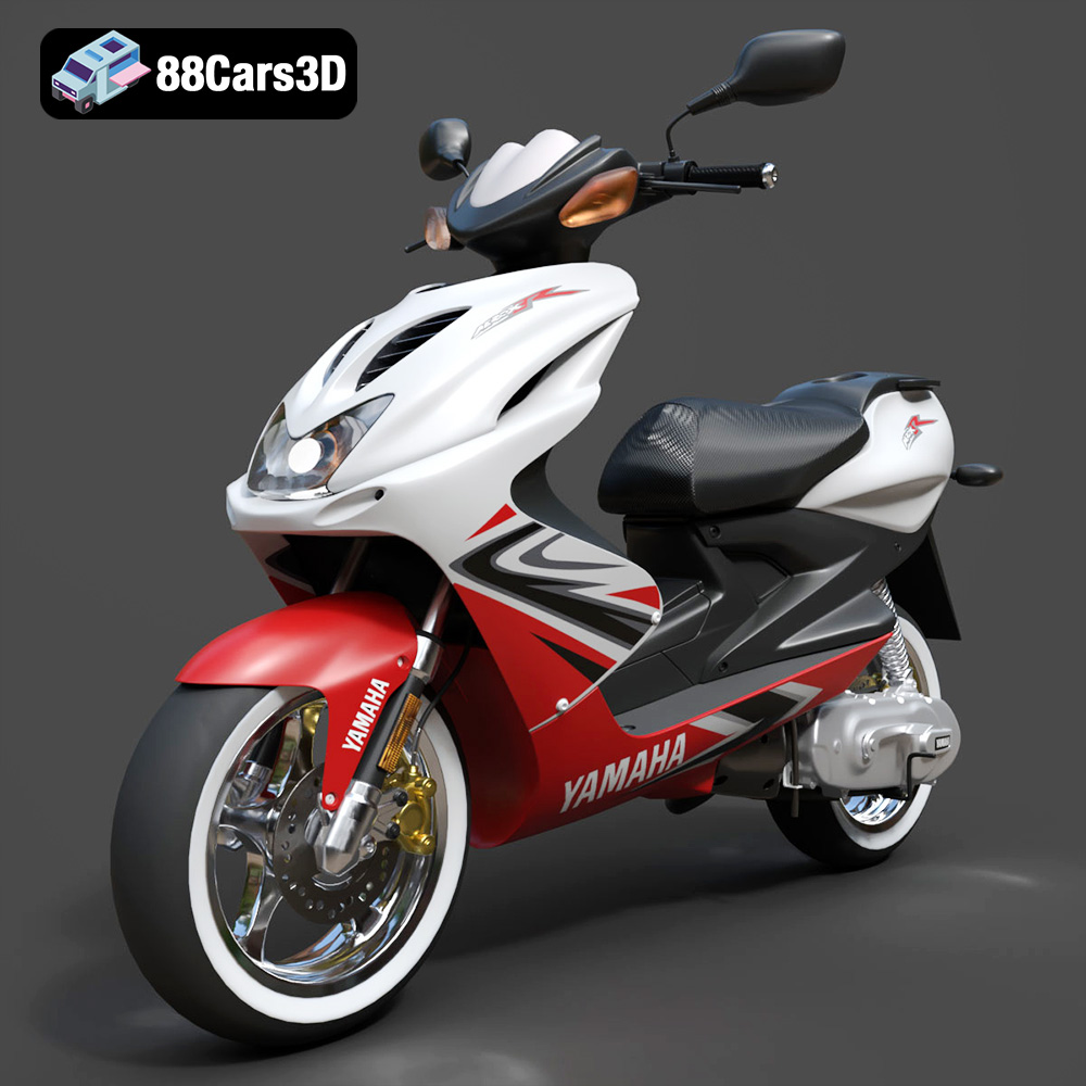
Yamaha Aerox R-002 2024 3D Model
Texture: Yes
Material: Yes
Download the Yamaha Aerox R-002 2024 3D Model featuring clean geometry, realistic detailing, and a fully modeled interior. Includes .blend, .fbx, .obj, .glb, .stl, .ply, .unreal, and .max formats for rendering, simulation, and game development.
Price: $19.99
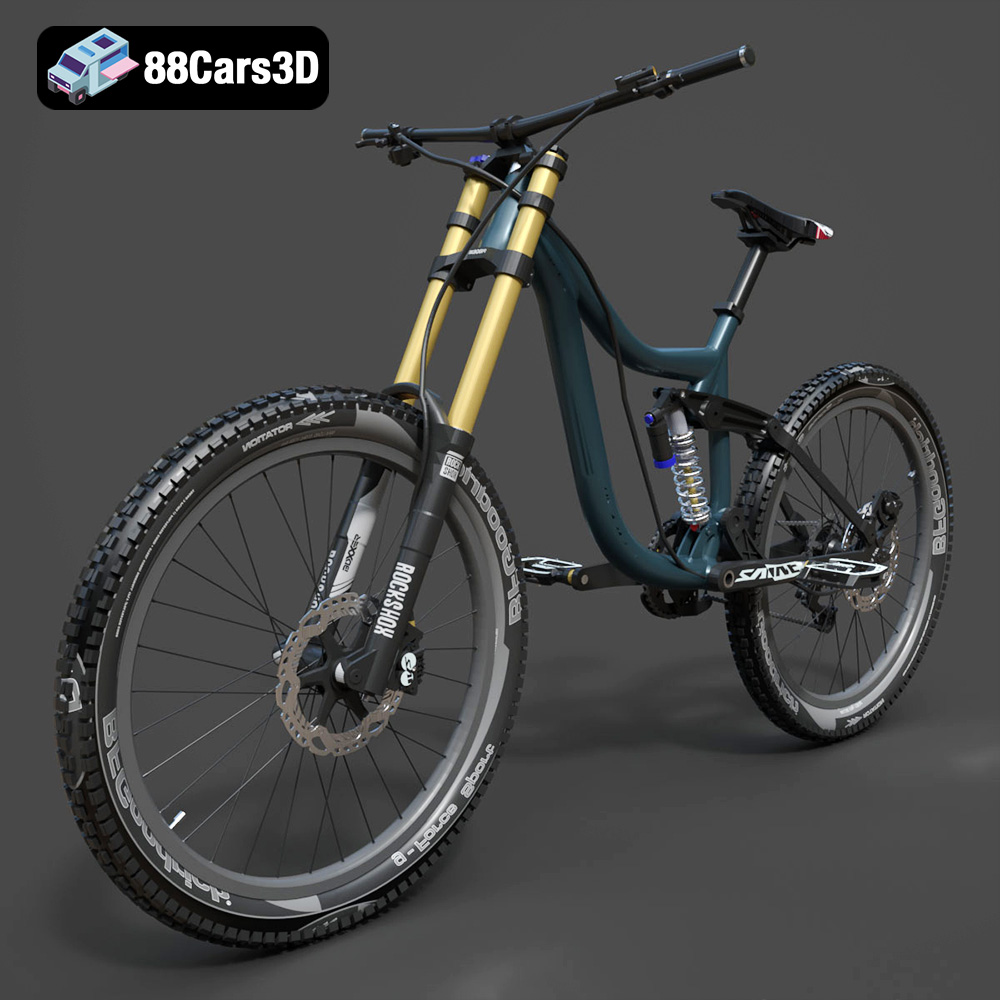
Mototsikly Downhill Bike-002 3D Model
Texture: Yes
Material: Yes
Download the Mototsikly Downhill Bike-002 3D Model featuring clean geometry, realistic detailing, and precise mechanical components. Includes .blend, .fbx, .obj, .glb, .stl, .ply, .unreal, and .max formats for rendering, simulation, and game development.
Price: $19.99
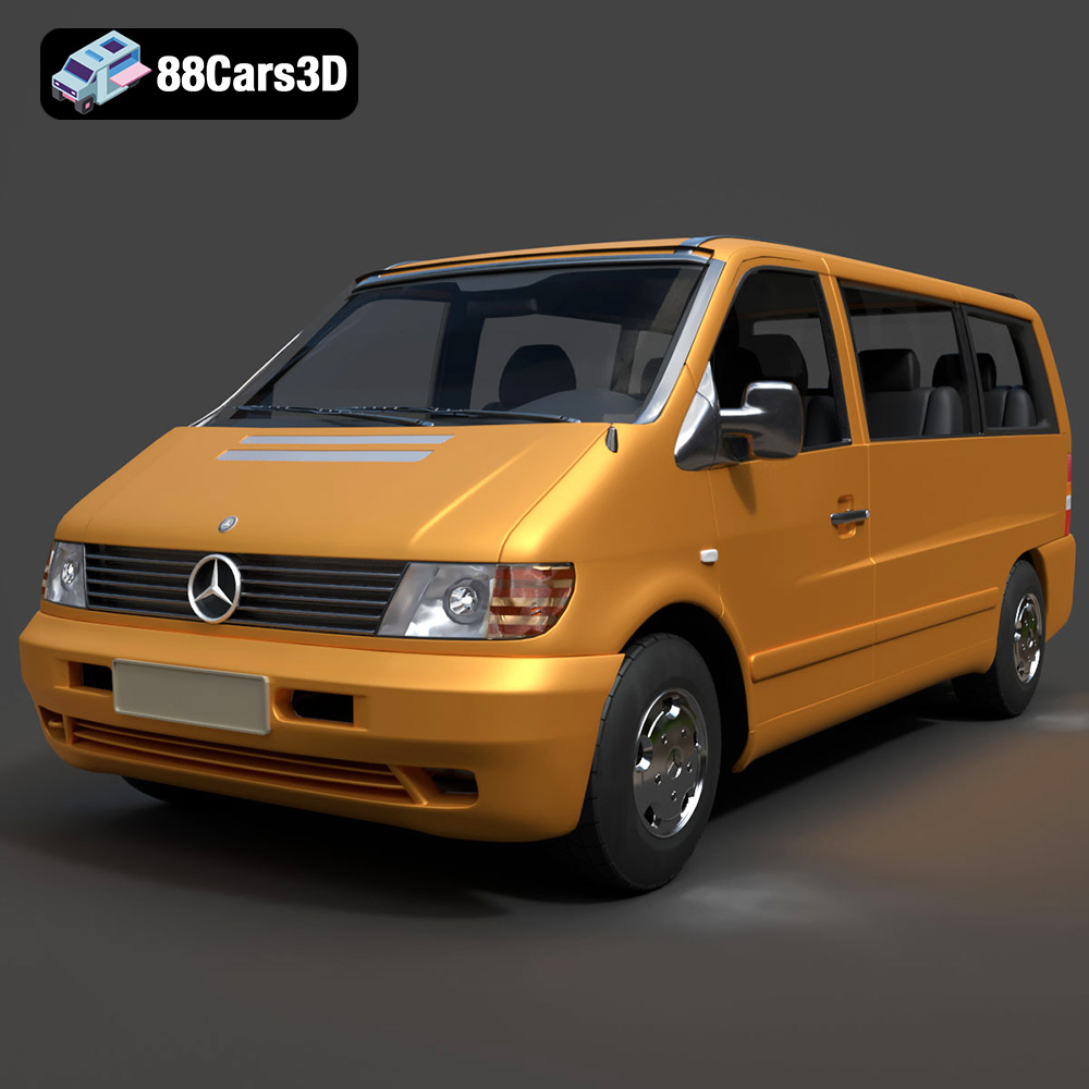
Mercedes-Benz Vito Passenger Van 3D Model
Texture: Yes
Material: Yes
Download the Mercedes-Benz Vito Passenger Van 3D Model featuring clean geometry, realistic detailing, and a fully modeled interior. Includes .blend, .fbx, .obj, .glb, .stl, .ply, .unreal, and .max formats for rendering, simulation, and game development.
Price: $19.99
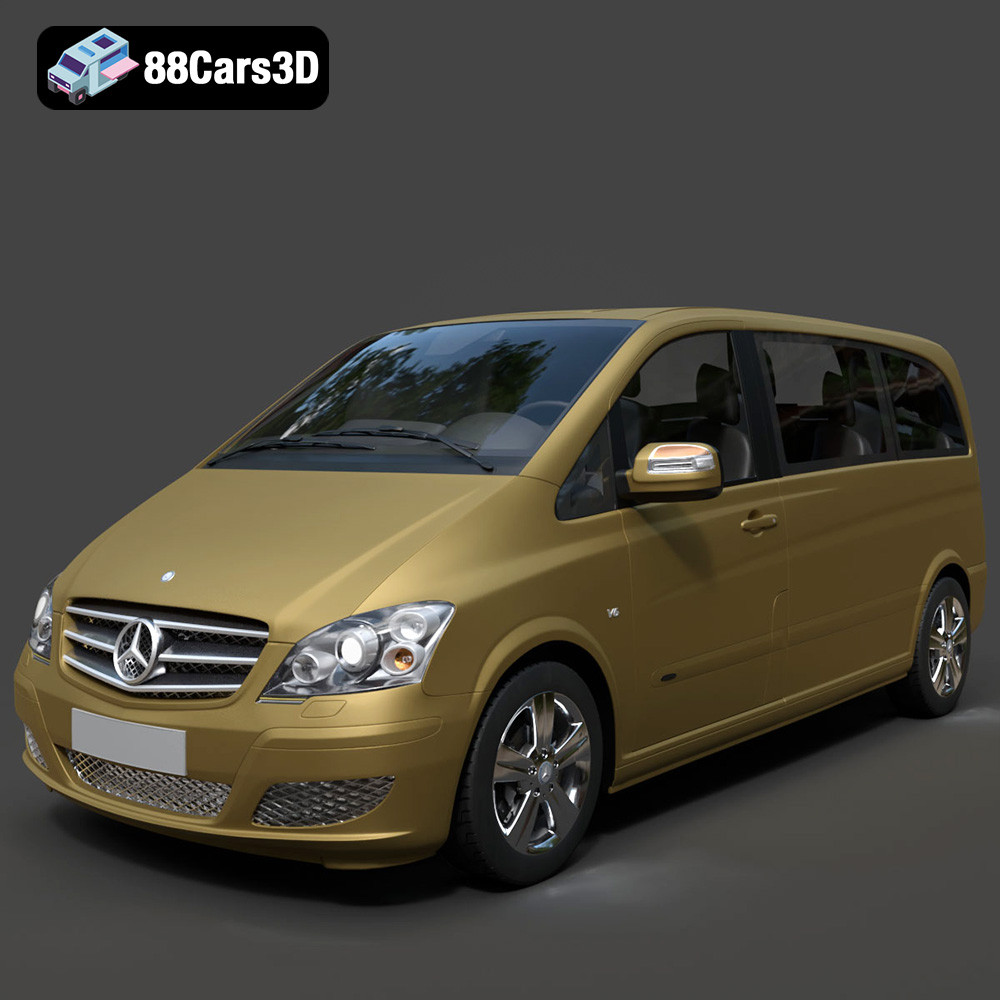
Mercedes-Benz Viano 2010 3D Model
Texture: Yes
Material: Yes
Download the Mercedes-Benz Viano 2010 3D Model featuring clean geometry, realistic detailing, and a fully modeled interior. Includes .blend, .fbx, .obj, .glb, .stl, .ply, .unreal, and .max formats for rendering, simulation, and game development.
Price: $19.99

Emt Avtobus 007 3D Model
Texture: Yes
Material: Yes
Download the Emt Avtobus 007 3D Model featuring clean geometry, realistic detailing, and a fully modeled interior. Includes .blend, .fbx, .obj, .glb, .stl, .ply, .unreal, and .max formats for rendering, simulation, and game development.
Price: $19.99
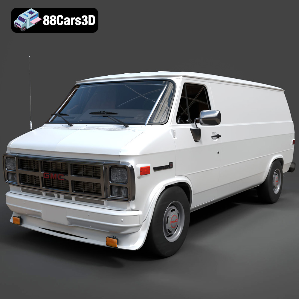
GMC Vandura G-1500 1983 3D Model
Texture: Yes
Material: Yes
Download the GMC Vandura G-1500 1983 3D Model featuring clean geometry, realistic detailing, and a fully modeled interior. Includes .blend, .fbx, .obj, .glb, .stl, .ply, .unreal, and .max formats for rendering, simulation, and game development.
Price: $19.99
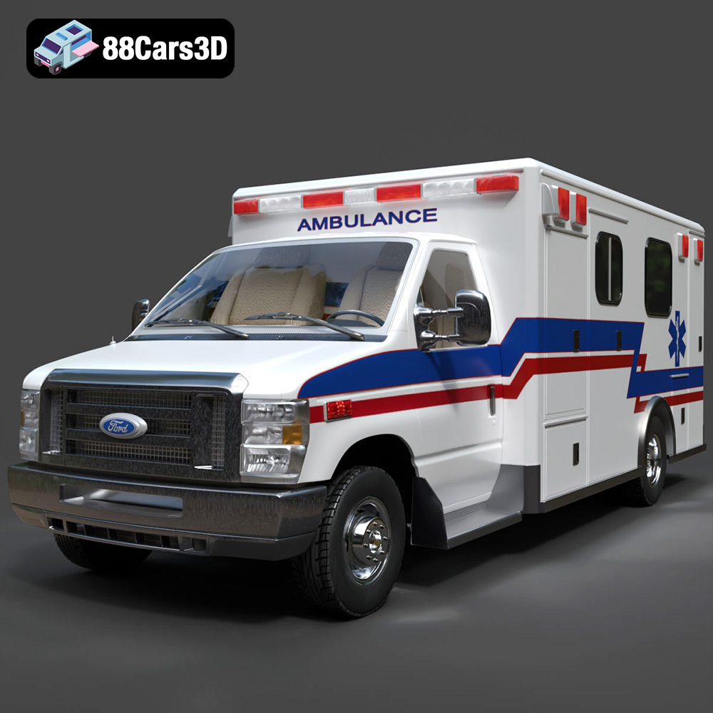
Ford E-450 Ambulance 3D Model
Texture: Yes
Material: Yes
Download the Ford E-450 Ambulance 3D Model featuring clean geometry, realistic detailing, and a fully modeled interior. Includes .blend, .fbx, .obj, .glb, .stl, .ply, .unreal, and .max formats for rendering, simulation, and game development.
Price: $19.99
