
“`html
Mastering Complex Geometry: Your Guide to Flawless STL 3D Prints
The world of 3D printing is a fascinating blend of digital design and tangible creation. As enthusiasts and professionals alike push the boundaries of what’s possible, we encounter increasingly intricate designs, especially in detailed models like those found on platforms like 88cars3d.com. Recreating these complex geometries – think delicate spoilers, intricate wheel spokes, or the subtle curves of a classic car body – on your 3D printer can be a rewarding, yet challenging, endeavor. Many aspiring makers find themselves battling issues like overhang failures, stringing, layer separation, and support removal nightmares. This comprehensive guide dives deep into the technical aspects of 3D printing complex STL files, transforming potential failures into print successes. We’ll explore everything from the fundamental structure of STL files and meticulous slicer settings to advanced support strategies and essential post-processing techniques. By the end of this article, you’ll have a robust understanding and a practical toolkit to tackle even the most intricate 3D printable car models with confidence.
Deconstructing the STL: Understanding the Foundation of Your Print
Before we even load a file into our slicer, a fundamental understanding of the STL (STereoLithography) format is crucial. While ubiquitous, its simplicity can sometimes lead to challenges with complex models. An STL file represents a 3D surface geometry as a collection of triangular facets. Each triangle is defined by three vertices and a normal vector, which dictates the outward-facing direction of the surface. This mesh-based representation is excellent for conveying shape but lacks information about internal structure, color, or material properties. For complex models, especially those with fine details or delicate features common in high-quality printable car models, the quality of this mesh is paramount.
Mesh Topology and its Impact on Printability
The ‘topology’ refers to how these triangles are connected. A ‘watertight’ or ‘manifold’ mesh is one that encloses a volume without holes, intersecting faces, or non-manifold edges (where more than two faces meet at an edge). Non-manifold geometry is a primary source of slicing errors and print failures. Slicers interpret the mesh to build toolpaths, and if the mesh is inconsistent or broken, the slicer can get confused, leading to missing sections, incorrect outer shells, or failed supports. For models downloaded from marketplaces such as 88cars3d.com, which often focus on high detail and printability, the meshes are typically well-constructed. However, if you’re working with custom designs or modifying existing ones, using mesh repair software becomes essential.
Essential Mesh Repair Tools and Techniques
Software like Meshmixer, Blender, or even Netfabb (in its various forms) are invaluable for checking and repairing STL files. The process generally involves:
- Auditing the Mesh: Tools like ‘Select Non-Manifold’ in Meshmixer or Blender’s ‘3D-Print Toolbox’ addon will highlight problem areas.
- Hole Filling: Simple holes can often be automatically filled, but complex gaps may require manual patching.
- Removing Internal Geometry: Sometimes, models can contain internal faces that don’t contribute to the outer shell but can confuse slicers.
- Checking Normals: Ensuring all faces have consistent outward-facing normals is vital.
- Reducing Triangle Count (if necessary): While high detail is good, an excessively dense mesh can slow down slicing. Decimation tools can reduce the triangle count without significant loss of visual fidelity.
For printable car models, ensuring details like thin fins, mirrors, or aerodynamic elements are represented by solid, connected geometry is key to preventing them from breaking off during printing or support removal.
Slicing for Success: Precision Parameters for Complex Prints
The slicer is your bridge between the digital model and the physical printer. It translates the STL file into layer-by-layer instructions (G-code) that your 3D printer follows. When dealing with complex geometry, default slicer settings are rarely optimal. We need to meticulously adjust parameters to accommodate fine details, overhangs, and intricate structures.
Layer Height vs. Print Time: The Delicate Balance
Layer height is one of the most impactful settings. A smaller layer height (e.g., 0.1mm) results in finer detail, smoother curves, and better reproduction of subtle features like panel gaps or intricate grilles. However, it also significantly increases print time. For highly detailed car models, a layer height between 0.1mm and 0.15mm is often a good compromise. Larger layer heights (0.2mm – 0.3mm) are faster but can introduce visible stepping on curves and may struggle with very fine details. Experimentation is key here; print a small, detailed section of your model at different layer heights to find the sweet spot for your printer and desired outcome.
Infill Strategies for Strength and Weight
Infill provides internal support and defines the model’s structural integrity. For display models, high infill percentages are often unnecessary and increase print time and material usage. An infill density of 10-20% is typically sufficient for structural support of external features. The choice of infill pattern also matters. Patterns like ‘Gyroid’ or ‘Cubic’ offer good strength in multiple directions and can be beneficial for supporting thin walls or delicate components. For purely aesthetic prints, you might even consider ‘Lightning’ infill (available in Cura and PrusaSlicer), which only adds support where needed internally, drastically reducing print time and material.
Speed and Temperature Tuning for Quality
Printing complex geometries often requires slower print speeds, especially for outer walls and small features. Reducing outer wall speed to 30-40 mm/s can dramatically improve surface quality and adhesion of fine details. Print temperature might also need slight adjustments. Slightly higher temperatures can improve layer adhesion, crucial for preventing parts from detaching during printing, particularly on tall, thin structures. Conversely, slightly lower temperatures can reduce stringing, which is common with complex designs featuring many travel moves. Always perform temperature towers and retraction tests when changing filaments or dialing in settings for a new model.
The Art of Supports: Enabling the Impossible
Complex geometries frequently involve overhangs and bridges that a 3D printer cannot create in mid-air. This is where support structures come into play. Their primary purpose is to build temporary scaffolding that the printer can create, allowing the actual model geometry to be printed on top. However, supports can be one of the most challenging aspects of 3D printing, especially when dealing with intricate models where delicate parts might be damaged during removal.
Automatic vs. Manual Support Generation
Most slicers offer automatic support generation, which can be a good starting point. However, for complex car models with specific features like undercuts, thin spoilers, or intricate wheel wells, automatic supports often generate excessive material, are difficult to remove without damaging the model, or fail to adequately support critical areas. Learning to manually paint or block supports in your slicer is a crucial skill. You can designate specific areas that *need* support and areas that do not, significantly reducing post-processing time and risk of damage.
Support Types and Settings for Clean Removal
Different support types exist, each with pros and cons:
- Normal/Grid Supports: Standard, dense supports. Can be difficult to remove from detailed surfaces.
- Tree/Organic Supports (e.g., Cura’s ‘Tree Support’, PrusaSlicer’s ‘Organic’): These branches out from a base, touching the model at minimal points. They often use less material, print faster, and are significantly easier to remove from detailed surfaces, making them ideal for models from 88cars3d.com.
- Custom Supports: Using primitive shapes (cubes, cylinders) in your CAD or slicer software to manually build support structures.
Key settings for optimizing supports include:
- Support Z Distance: Controls the gap between the support and the model. A larger gap (e.g., 0.2mm – 0.3mm) makes removal easier but can lead to poorer surface quality on the supported overhang. A smaller gap (e.g., 0.1mm – 0.15mm) improves surface quality but makes removal harder. Finding the right balance is essential.
- Support XY Distance: Controls the horizontal gap. A larger XY distance can make supports easier to break away.
- Support Interface: Adding a dense interface layer on top of the supports greatly improves the surface finish of the supported overhang.
- Support Density: Lower density for easier removal, higher for more stability.
For car models, strategically placing supports under overhangs like bumpers, spoilers, or wheel arches, while avoiding direct contact with delicate elements like side mirrors or antennas, is key. Tree supports are often the best choice here.
Optimizing Print Orientation and Bed Adhesion
How you orient your model on the print bed and ensure it sticks properly can be the difference between a successful print and a failed one, especially for tall, complex shapes. Incorrect orientation can exacerbate overhang issues, necessitate more complex support structures, and increase the risk of warping or detachment.
Strategic Orientation for Overhangs and Supports
The goal of orientation is to minimize the need for supports and place them in less visible areas. For many car models, printing them upright often presents the largest surface area for bed adhesion and keeps the most detailed side (usually the top) facing upwards, reducing the need for supports underneath. However, if the underside has critical details or deep overhangs (like a complex chassis), it might be beneficial to orient the model at an angle (e.g., 15-45 degrees). This can convert sharp overhangs into gentler slopes, reducing support material and improving print quality. Experiment by rotating the model in your slicer and observing how the necessary supports change.
Ensuring Robust Bed Adhesion for Complex Parts
A large, flat base provides good adhesion, but complex models can have smaller contact points or warp due to uneven cooling. Essential practices include:
- Clean Build Plate: Always ensure your print bed is free of dust, grease, and old filament residue. IPA (Isopropyl Alcohol) is your best friend here.
- Leveling: A perfectly level bed is non-negotiable. Auto bed leveling systems help, but manual checks are still recommended.
- Bed Temperature: Maintain the correct bed temperature for your filament (e.g., 50-60°C for PLA, 70-80°C for PETG/ABS).
- Adhesion Aids: For challenging prints, consider using adhesion aids like glue stick, hairspray, or specialized bed adhesives. PEI sheets offer excellent adhesion for many materials.
- Brims/Rafts: For models with small footprints or a high center of gravity, adding a brim (a single layer flat area around the base) or a raft (a thicker base structure) can significantly improve adhesion and prevent detachment during the print. For complex car models, a brim is often sufficient and easier to remove than a raft.
Consider the weight distribution of the car model. If it’s very tall and narrow, it’s more prone to tipping or detaching. A brim is almost always recommended for such prints.
Material Selection and Printer Calibration: The Unsung Heroes
The best slicing strategies and support techniques can be undermined by poor material choice or an uncalibrated printer. Selecting the right filament and ensuring your printer is performing optimally are fundamental to achieving high-quality results, especially with intricate printable car models.
Choosing the Right Filament for Detail and Durability
Different filaments offer different properties:
- PLA (Polylactic Acid): The most common and easiest to print. It offers excellent detail, low warping, and is ideal for display models. However, it can be brittle and has a low glass transition temperature (meaning it can deform under heat).
- PETG (Polyethylene Terephthalate Glycol): More durable and temperature-resistant than PLA, with good layer adhesion. It can be slightly more prone to stringing, requiring careful retraction tuning.
- ABS (Acrylonitrile Butadiene Styrene): Very durable and temperature-resistant, but notoriously difficult to print due to warping and fumes. Requires an enclosure and careful temperature control. Not recommended for beginners or intricate models unless specific strength is needed.
- Resin (SLA/DLP): For extreme detail that FDM cannot achieve (e.g., tiny badges, intricate interior details), resin printers excel. They use UV-curable liquid resin and offer incredibly smooth surfaces and sharp edges. However, they require more involved post-processing (washing and curing) and the materials can be more brittle.
For most high-quality printable car models from sources like 88cars3d.com, PLA is the go-to material for FDM printing due to its detail reproduction and ease of use. If you have access to a resin printer, that’s often the ultimate choice for hyper-realistic detail.
Printer Calibration: The Foundation of Quality
A well-calibrated printer is essential for predictable and high-quality prints. Key calibration steps include:
- E-step Calibration: Ensures your extruder pushes the correct amount of filament.
- PID Tuning (Hotend & Bed): Stabilizes temperatures, preventing fluctuations that cause layer inconsistencies.
- Flow Rate/Extrusion Multiplier: Fine-tunes the amount of filament extruded to prevent over- or under-extrusion, critical for precise details.
- First Layer Calibration: Ensures perfect adhesion and a smooth start to every print.
- Dimensional Accuracy: Calibrate your X, Y, and Z axes so printed dimensions match the model’s dimensions.
Regular maintenance, such as cleaning and lubricating linear rails/rods, checking belt tension, and ensuring your nozzle is clean and not worn, also plays a vital role in consistent performance, especially when tackling complex prints that take many hours.
Post-Processing: Bringing Your Masterpiece to Life
Once your complex 3D print is successfully off the build plate, the journey isn’t over. Post-processing is where you refine the raw print, remove imperfections, and prepare it for display or further assembly. For intricate car models, this stage is crucial for achieving a professional, polished look.
Support Removal: The Gentle Touch
This is often the most dreaded part. Patience and the right tools are key:
- Tools: Needle-nose pliers, flush cutters, hobby knives (X-Acto), dental picks, and sometimes even small files or rotary tools (like a Dremel) with fine bits.
- Technique: Start by removing the largest sections of support first. Use flush cutters to snip away cleanly. For smaller, stubborn pieces, gently pry with picks or a knife. If supports are attached to delicate model surfaces, use a hobby knife to carefully cut the support material away from the model, rather than trying to rip the support off. For tree supports, they often snap off cleanly with minimal contact points.
- Cleanup: After support removal, you’ll likely have small nubs or blemishes. These can be carefully sanded down or shaved off with a sharp knife.
If using resin prints, support removal is similar but requires gloves and proper ventilation due to uncured resin.
Sanding, Filling, and Priming for a Smooth Finish
Even with optimal print settings, layer lines can be visible. Sanding is the primary method for smoothing these out. Start with coarser grit sandpaper (e.g., 120-220 grit) to remove significant lines and support nubs, then progressively move to finer grits (e.g., 400, 800, 1000+ grit) for a smooth surface. For FDM prints, filling layer lines can be achieved with:
- Wood Filler/Spackle: Easy to apply and sand, good for minor imperfections.
- Automotive Body Filler: For more serious imperfections or larger models, this provides a very smooth, durable surface.
- Epoxy Resins: Can be brushed or applied to fill gaps and smooth surfaces.
After sanding and filling, a primer coat is essential. It reveals any remaining imperfections, provides a uniform surface for paint, and helps paint adhere better. Automotive primers work exceptionally well for 3D prints.
Painting and Assembly: The Final Touches
Once primed and smooth, your model is ready for painting. Acrylic paints (airbrushed or hand-painted) are popular. For realistic car finishes, consider automotive spray paints. Multiple thin coats are always better than one thick coat. If your model consists of multiple parts (e.g., body, wheels, interior), careful assembly using super glue (cyanoacrylate) or specialized plastic adhesives is required. Ensure parts fit snugly before gluing, and use clamps or tape to hold them in place while the adhesive cures.
Printing complex geometries in STL format, especially detailed 3D printable car models, is a journey that rewards patience, precision, and a deep understanding of your 3D printer and software. By mastering the nuances of STL file preparation, meticulously tuning your slicer settings, strategically employing supports, optimizing orientation, selecting appropriate materials, ensuring printer calibration, and dedicating time to post-processing, you can overcome common printing failures. The wealth of high-quality, print-ready STL files available on platforms like 88cars3d.com provides an excellent starting point for these advanced prints. Embrace the learning process, experiment with settings, and don’t be discouraged by occasional setbacks. Each print is an opportunity to refine your skills and bring stunningly detailed automotive creations to life, one layer at a time.
“`
Featured 3D Car Models

The Italian Legends Bundle 5 Ultimate Supercar 3D Models STL Optimized
Texture: Yes | Material: Yes | 3D Printable: Yes. Download the Italian Thoroughbreds Bundle featuring 5 iconic 3D models: Lamborghini Huracán Performante, Ferrari 458 Italia, Lamborghini Urus, Diablo SV, and Maserati GT. Optimized for 4K rendering and 3D printing (STL included). Save 50% with this ultimate Italian vehicle collection.
Price: $199.99

Elite Future Mobility: EV & Autonomous SUV Bundle (4 High-End 3D Models)3D Printable STL
Download the Elite Future Mobility Bundle featuring 4 highly optimized 3D models: Tesla Model S, Avatr 11, Li L9, and Zoox Robotaxi. Perfect for ArchViz, Smart City renders, and game dev. Optimized for Unreal Engine and Blender. Includes .fbx, .obj, and .max formats.
Price: $99

German Luxury & Performance Bundle – High-End 3D Vehicle Collection3D Printable STL
🚗 5 Iconic German Cars (BMW M4 G82, M5 CS, X3, 1 Series & Mercedes E-Class). ✅ Optimized for ArchViz: Ready for Corona & V-Ray. 💰 Save €71 with this limited-time collection! 🚀 Instant Download after purchase.
Price: $119

Extreme Off-Road & Survival 3D Models Bundle (4-in-1 Pack)3D Printable STL
Download the Extreme Off-Road & Survival 3D Models Bundle! Includes the Brabus 800 Adventure, Dodge Ram Bigfoot, Spec Truck, and a Caravan. Save over €210 on this premium 4-in-1 off-grid vehicle pack for ArchViz and game development.
Price: $149.99
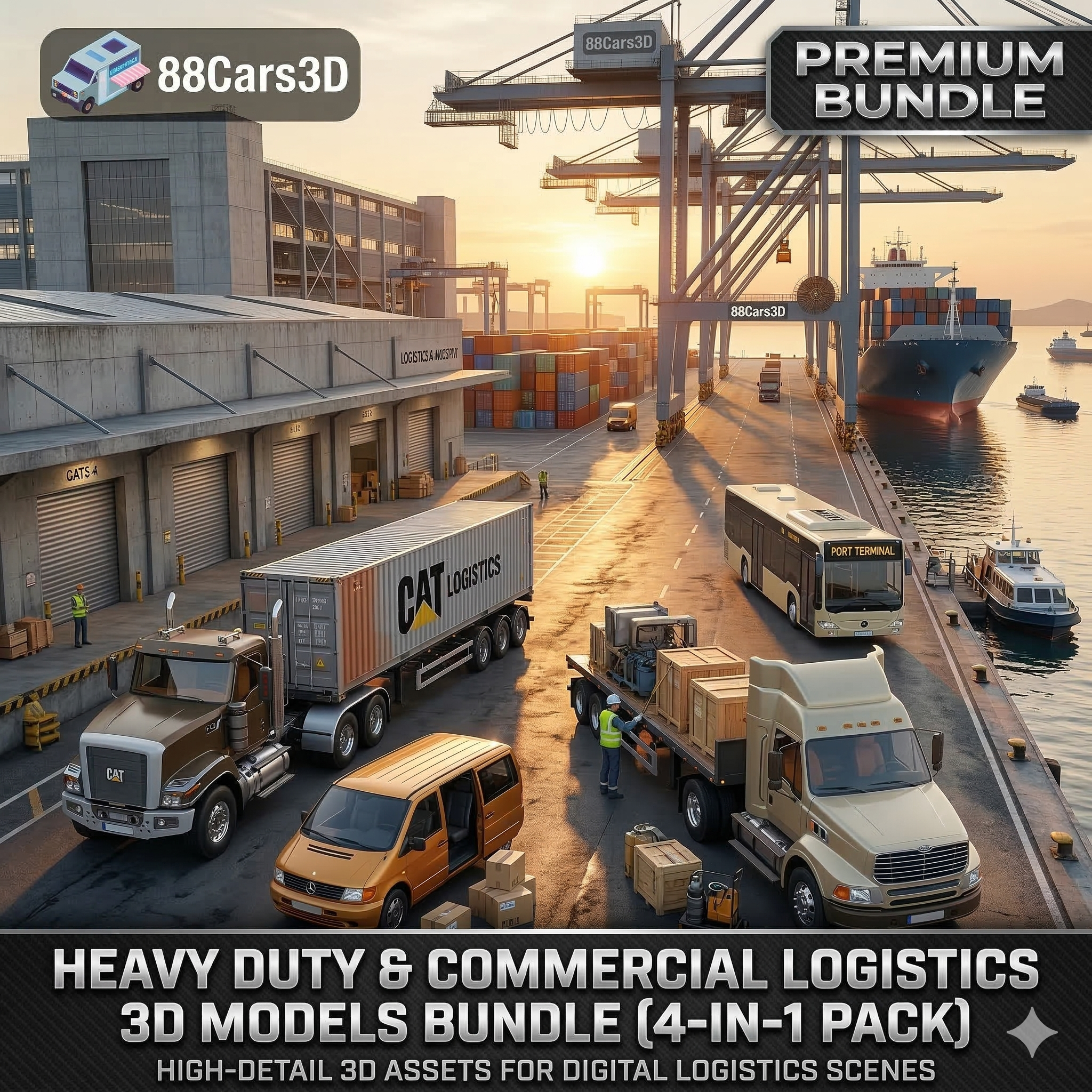
Heavy Duty & Commercial Logistics 3D Models Bundle (4-in-1 Pack)3D Printable STL
Download the Heavy Duty & Commercial Logistics 3D Models Bundle! Includes the Ford Sterling, Caterpillar CT680, Mercedes Citaro Bus, and Vito Van. Save over €130 on this massive, game-ready 4-in-1 industrial vehicle pack.
Price: $109.99

The Ultimate Garage Props & Custom Motorcycles 3D Models Bundle 3D Printable STL
Download the Ultimate Custom Motorcycles 3D Models Bundle. Includes a Custom Chopper, Ducati 916 Café Fighter, Harley XR1200X, and BMW K100. Perfect premium props for luxury ArchViz garages. Save over €250 today!
Price: $159.99

Japanese Legends: JDM Street Racing 3D Models Bundle (5-in-1 Pack) Nissan Mitsubishi Honda Mazda Toyota 3D Printable STL
Download the ultimate JDM Street Racing 3D Models Bundle! Includes the Nissan GT-R, Toyota Supra, Mazda RX-7, Lancer Evo IX, and Honda NSX. Save big on this highly optimized, game-ready 5-in-1 Japanese legend car pack.
Price: $129.99

American Muscle & Classics Pack 4 in 1 Ford Dodge Chevrolet 3D Printable STL
Download the ultimate American Muscle & Cinematic Classics 3D Models Bundle! Includes the Dodge Charger ’68, Mustang Eleanor GT500, Camaro Z28 ’79, and a custom ’69 Mustang. Save over €240 on this game-ready, premium 4-in-1 pack.
Price: $149.99
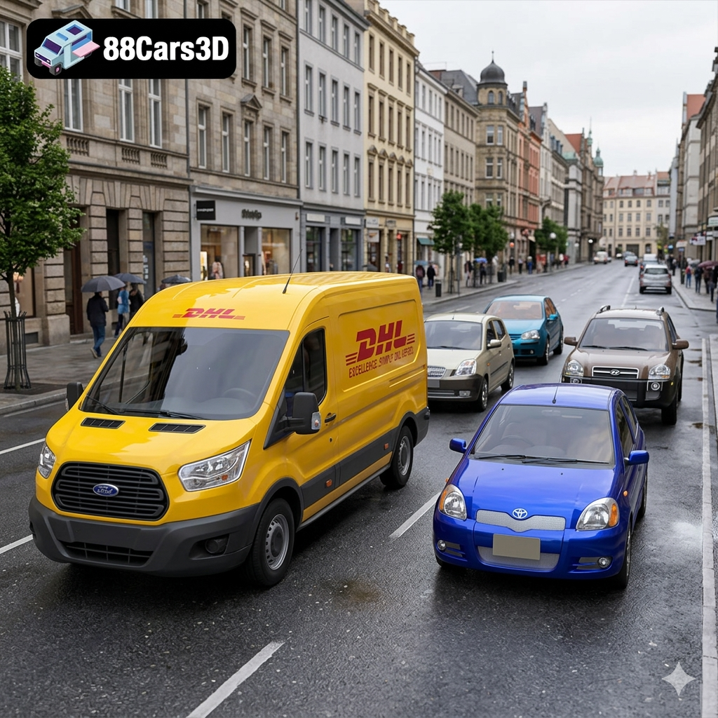
Everyday City Traffic Essentials pack 5in1 Hyundai Kia Volkswagen Toyota Ford 3D Printable STL
Download the Everyday City Traffic 3D Models Bundle. Includes the VW Golf, Kia Picanto, Hyundai Tucson, Toyota Yaris, and a DHL Ford Transit Van. Save big on this 5-in-1 pack, perfectly optimized for realistic ArchViz streets and game traffic.
Price: $99.99
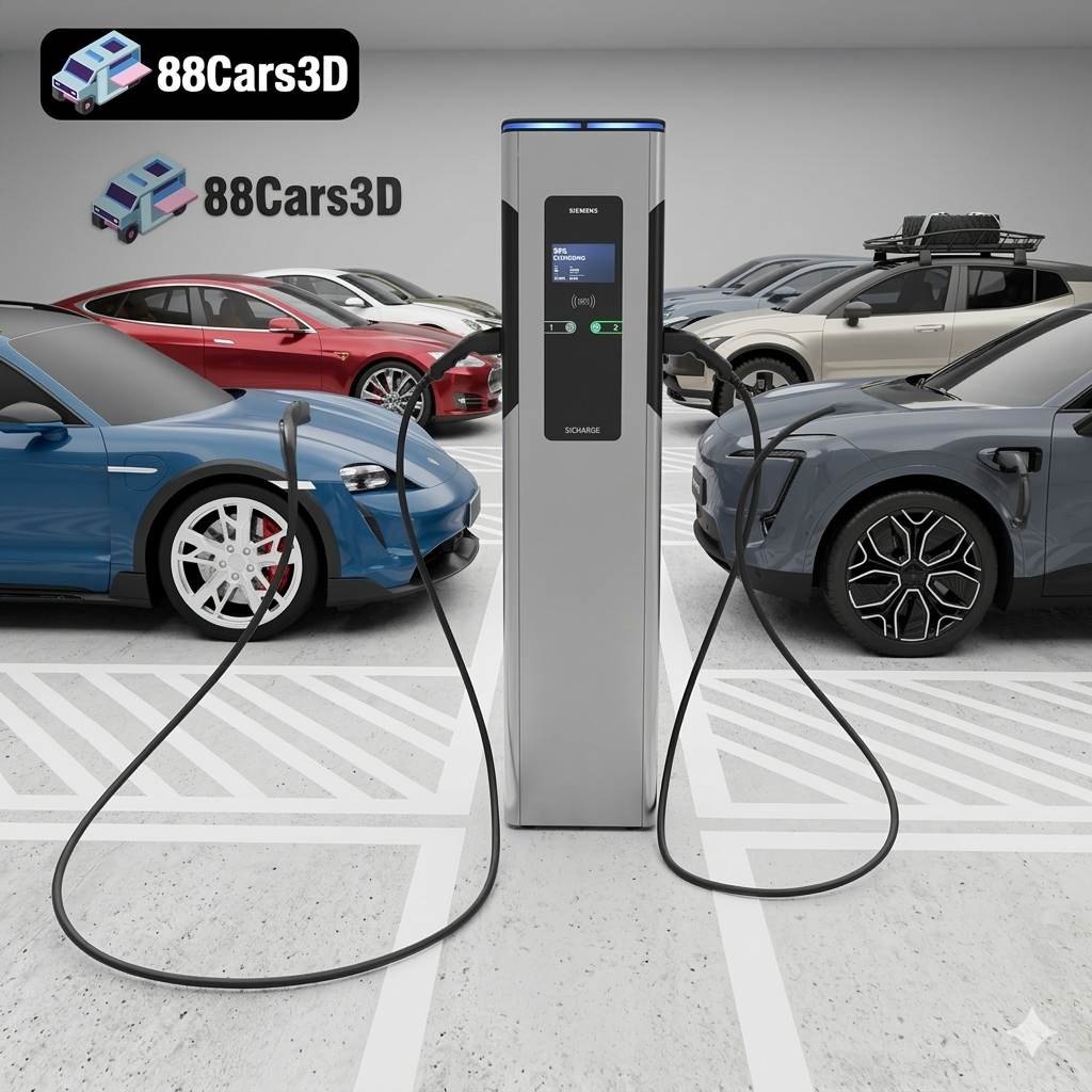
The Future of Mobility: Smart City EV 3D Models Bundle (5-in-1 Pack) Volvo Tesla AVATR Porsche 3D Printable STL
Download the Future of Mobility EV 3D Models Bundle. Includes the Volvo EX30, Tesla Model S, AVATR 11, Porsche Taycan, and a Siemens EV Charger. Save big on this highly optimized 5-in-1 pack for ArchViz and game development!
Price: $89.99
