Get 50% OFF All Premium 3D & STL Models!
In the exhilarating world of 3D automotive design, game asset development, and high-fidelity visualization, every detail counts. From the gleam of polished chrome to the subtle imperfections of weathered paint, achieving photorealism is the ultimate goal. Among the most challenging yet rewarding materials to replicate is carbon fiber. Its distinctive woven pattern, deep reflective qualities, and anisotropic sheen make it a staple in modern performance vehicles and futuristic concepts. Mastering the art of creating realistic carbon fiber in 3D can elevate your automotive models from good to truly breathtaking, adding a layer of authenticity that captivates viewers and clients alike.
This comprehensive guide dives deep into the technical intricacies of crafting visually stunning carbon fiber materials across various 3D software and rendering engines. Whether you’re a seasoned 3D artist looking to refine your techniques or a budding enthusiast eager to tackle advanced materials, you’ll discover specific workflows, technical specifications, and industry best practices. We’ll explore everything from essential 3D modeling topology and meticulous UV mapping to advanced Physically Based Rendering (PBR) shader networks and crucial optimization strategies for game engines and AR/VR applications. Get ready to unlock the secrets behind truly convincing carbon fiber, ensuring your 3D car models stand out in any digital environment, much like the premium 3D car models available on 88cars3d.com.
Before we can digitally recreate carbon fiber, it’s crucial to understand its physical properties and how light interacts with it. Real carbon fiber is a composite material made from woven carbon filaments embedded in a polymer resin matrix. This unique structure gives it incredible strength-to-weight ratio and its characteristic appearance. The visual complexity arises from several factors:
The most recognizable feature of carbon fiber is its intricate weave pattern, typically a twill weave (e.g., 2×2 or 3×1). This weave dictates how light reflects across its surface. Due to the orientation of the fibers, the reflections appear elongated and stretch along the direction of the weave, a phenomenon known as anisotropy. This is a critical characteristic that must be accurately simulated in 3D to avoid a flat, unrealistic look. The depth of the weave, with fibers slightly above or below each other, also creates subtle self-shadowing and ambient occlusion, enhancing its realism. Observing real-world samples under different lighting conditions helps immensely in capturing these nuances.
Most aesthetic carbon fiber parts are finished with a clear coat of resin, often polished to a high gloss. This clear coat adds a layer of depth and refraction over the woven carbon, making the material appear to have a glossy shell over a subsurface pattern. This is not merely a surface reflection; it’s a volumetric effect that influences how highlights and environmental reflections are perceived. The thickness and clarity of this clear coat significantly impact the overall look, contributing to the famous “wet look” or deep luster of well-finished carbon fiber.
While the material itself defines the carbon fiber look, a well-constructed 3D model is the foundation. Achieving realistic carbon fiber means preparing your geometry to receive the material properly, especially concerning light interaction and UV mapping. Clean, efficient topology is paramount for any high-quality automotive 3D model.
For automotive models, especially those with smooth, sweeping curves designed to showcase materials like carbon fiber, a quad-based topology is always recommended. This ensures predictable subdivision and smooth transitions, which are vital for capturing accurate reflections. Triangles and N-gons can introduce pinching or undesirable shading artifacts, particularly when using subdivision surfaces. Aim for even distribution of polygons and consistent edge flow that follows the contours of the car part. This is particularly important on areas where the carbon fiber pattern will be prominent, such as spoilers, diffusers, or interior trims.
Carbon fiber parts often have precise edges and subtle curvature. To enhance realism, ensure your model’s edges are supported by enough geometry to hold their shape after subdivision. Use techniques like adding holding loops or creasing edges (if your software and workflow support it) to define sharp lines without introducing excessive polycount. Small panel gaps and slight bevels along edges can catch light beautifully, further defining the carbon fiber part and separating it from adjacent surfaces. A tolerance of 0.5mm to 1mm for panel gaps is a good starting point, adjusting as needed for scale and context.
Impeccable UV mapping is non-negotiable for realistic carbon fiber. The distinctive weave pattern needs to flow seamlessly and uniformly across the surface, without stretching or visible seams. Poor UVs can instantly break the illusion, making your material appear painted on rather than integrated.
The first step in effective UV mapping is strategic seam placement. For a complex car body or individual carbon fiber panels, identify natural breaks or less visible areas where seams can be hidden. Think about how a real carbon fiber part would be manufactured and wrapped. Tools like Blender’s UV Editor offer robust features for this. In Blender 4.4, you can mark seams directly in Edit Mode (Ctrl+E > Mark Seam) and then unwrap (U > Unwrap) to generate UVs that respect these cuts. For more details on effective UV workflow, consult the Blender 4.4 Manual on UV Unwrapping.
After marking seams, the unwrapping process aims to lay out the 3D surface into 2D space with minimal distortion. Tools like Blender’s “Average Island Scale” and “Pack Islands” functions (found in the UV Editor’s UV menu) help ensure that all UV islands maintain a consistent texture density. This prevents the carbon fiber weave from appearing stretched or compressed on different parts of the model. For larger or more complex models, consider using UDIM workflows, which allow for multiple UV tiles, each with its own texture set. This enables incredibly high-resolution textures without hitting memory limits for a single UV map, crucial for showcasing fine carbon fiber details in close-up renders.
Physically Based Rendering (PBR) is the cornerstone of realism in modern 3D. A robust PBR workflow allows you to define materials based on real-world physics, ensuring they react correctly to light. For carbon fiber, this involves a specific combination of texture maps and shader parameters.
In Blender 4.4, the Principled BSDF shader is your best friend. It consolidates many parameters needed for PBR materials. Here’s a basic node setup:
In 3ds Max, you’ll typically use the Corona Physical Material or V-Ray Material. Both offer similar PBR parameters:
Beyond the fundamental PBR setup, several advanced techniques can push your carbon fiber materials into the realm of hyper-realism. These often involve adding subtle imperfections and layers of complexity that mimic real-world wear and tear.
No real-world material is perfectly clean or uniform. Incorporate subtle dust, fingerprints, water spots, and micro-scratches using grunge maps and blend nodes. These can be blended with your main material using a Mix Shader in Blender or blend layers in 3ds Max. For instance, a subtle dust layer could have a slightly higher roughness and a very light diffuse color, driven by an ambient occlusion or procedural noise mask. For scratches, you might use a scratch texture to subtly reduce roughness and increase the metallic value in those specific areas, mimicking exposed fibers or deeper damage.
High-end carbon fiber can sometimes exhibit a subtle sparkly effect from microscopic flakes within the resin, especially under direct light. This is an advanced effect that can be achieved with a few tricks:
Even the most perfectly crafted carbon fiber material will look dull without appropriate lighting. Automotive rendering demands a keen understanding of how light interacts with reflective surfaces to truly showcase the material’s qualities.
High Dynamic Range Images (HDRIs) are indispensable for realistic lighting. They provide both the environmental illumination and reflections, crucial for reflective materials like carbon fiber. Use a variety of HDRIs—from studio setups with softbox reflections to outdoor environments with sharp sunlight—to see how your carbon fiber reacts. A strong, defined light source (like the sun in an outdoor HDRI or a powerful studio light) will emphasize the anisotropic highlights and the depth of the clear coat. Ensure the HDRI resolution is high enough (e.g., 8K or 16K) to provide clean reflections without pixelation.
For product shots on platforms like 88cars3d.com, studio lighting often works best to highlight specific features. Use large, softbox-like area lights to create broad, flattering reflections that reveal the carbon fiber’s weave and gloss. Rim lights can be used to define the edges and curvature of the component. For environmental shots, ensure your carbon fiber material integrates seamlessly with the scene’s lighting. The reflections on the carbon fiber should accurately mirror the environment, enhancing immersion.
Strategic camera placement and composition are vital for showcasing carbon fiber. Position your camera to capture reflections and highlights that reveal the material’s unique characteristics. A slightly angled view, rather than a direct frontal shot, often allows the anisotropic glint to become more apparent. Experiment with different focal lengths to compress or exaggerate the perspective, further emphasizing the forms and the material’s interaction with light. Post-processing can then be used to further enhance these features, adjusting contrast and adding subtle bloom to highlights.
While photorealistic renders prioritize visual fidelity, game engines and AR/VR applications demand efficiency. Translating complex carbon fiber materials into optimized assets requires careful planning and execution.
For carbon fiber parts, especially on vehicles, implementing a robust LOD system is crucial. Create multiple versions of your carbon fiber model, each with decreasing polygon counts and simplified materials, for different distances from the camera. The highest LOD might use your detailed PBR setup with high-resolution textures, while lower LODs could utilize simpler shaders, lower resolution textures, or even baked-in ambient occlusion and lighting information to maintain visual consistency without performance overhead. This ensures that a detailed carbon fiber spoiler up close still looks good from a distance, without rendering unnecessary complexity. When purchasing 3D car models for games or AR/VR, look for models that come with well-defined LODs.
Texture atlasing involves combining multiple smaller textures into a single, larger texture. For a car model with many carbon fiber components, instead of having individual textures for each small part, atlas them together. This reduces the number of draw calls an engine needs to make, significantly improving performance. When creating your carbon fiber material, design its texture maps (Base Color, Normal, Roughness, Anisotropy Map) so they can be easily integrated into a larger texture atlas. This often means consistent tiling patterns and careful UV unwrapping.
For highly complex carbon fiber shader networks, especially those with multiple layers or intricate procedural elements, consider baking them down into simpler PBR texture maps. This means rendering the full material onto new texture maps (Base Color, Metallic, Roughness, Normal, Emissive, Ambient Occlusion) that can be used with a standard, less computationally intensive shader in a game engine. Tools like Blender (refer to the Blender 4.4 Manual on Render Baking) and Substance Painter excel at this, allowing you to retain much of the visual fidelity while vastly improving real-time performance. This is particularly important for mobile AR/VR experiences where computational resources are limited.
Choosing the right file format is essential for compatibility and optimization. For game engines like Unity and Unreal Engine, FBX is a common choice, as it supports meshes, materials, animations, and LODs. For AR/VR experiences, GLB (for glTF) and USDZ are increasingly popular due to their compact size and native support for PBR materials on mobile platforms. When exporting, ensure your carbon fiber textures are embedded or correctly linked, and that any specific PBR parameters (like anisotropy) are correctly translated or baked into maps.
Creating realistic carbon fiber in 3D is a nuanced process that requires a blend of technical understanding, artistic observation, and meticulous execution. From carefully sculpted topology and precise UV mapping to the construction of complex PBR shader networks and strategic optimization, every stage plays a vital role. The anisotropic reflections, the deep gloss of the clear coat, and the subtle imperfections are what bring this high-tech material to life in your digital automotive models.
By applying the techniques outlined in this guide, you can achieve a level of realism that truly captivates. Remember to continually reference real-world carbon fiber, experiment with different software features, and always strive for clean, efficient workflows. Whether your goal is a stunning promotional render, an immersive AR/VR experience, or a high-performance game asset, mastering carbon fiber will undoubtedly enhance the quality and perceived value of your work. For artists seeking top-tier 3D car models that already feature excellent materials and optimization, explore the extensive collection available on 88cars3d.com, where quality and detail are paramount. Embrace the challenge, and let your carbon fiber creations shine!
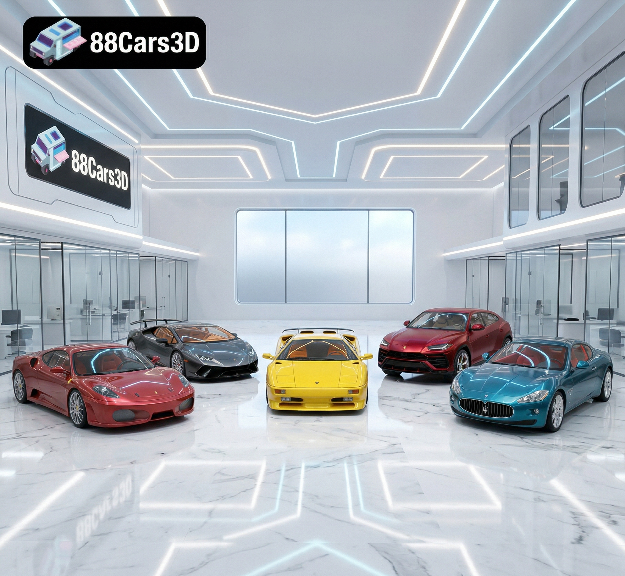
Texture: Yes | Material: Yes | 3D Printable: Yes. Download the Italian Thoroughbreds Bundle featuring 5 iconic 3D models: Lamborghini Huracán Performante, Ferrari 458 Italia, Lamborghini Urus, Diablo SV, and Maserati GT. Optimized for 4K rendering and 3D printing (STL included). Save 50% with this ultimate Italian vehicle collection.
Price: $199.99

Download the Elite Future Mobility Bundle featuring 4 highly optimized 3D models: Tesla Model S, Avatr 11, Li L9, and Zoox Robotaxi. Perfect for ArchViz, Smart City renders, and game dev. Optimized for Unreal Engine and Blender. Includes .fbx, .obj, and .max formats.
Price: $99

🚗 5 Iconic German Cars (BMW M4 G82, M5 CS, X3, 1 Series & Mercedes E-Class). ✅ Optimized for ArchViz: Ready for Corona & V-Ray. 💰 Save €71 with this limited-time collection! 🚀 Instant Download after purchase.
Price: $119
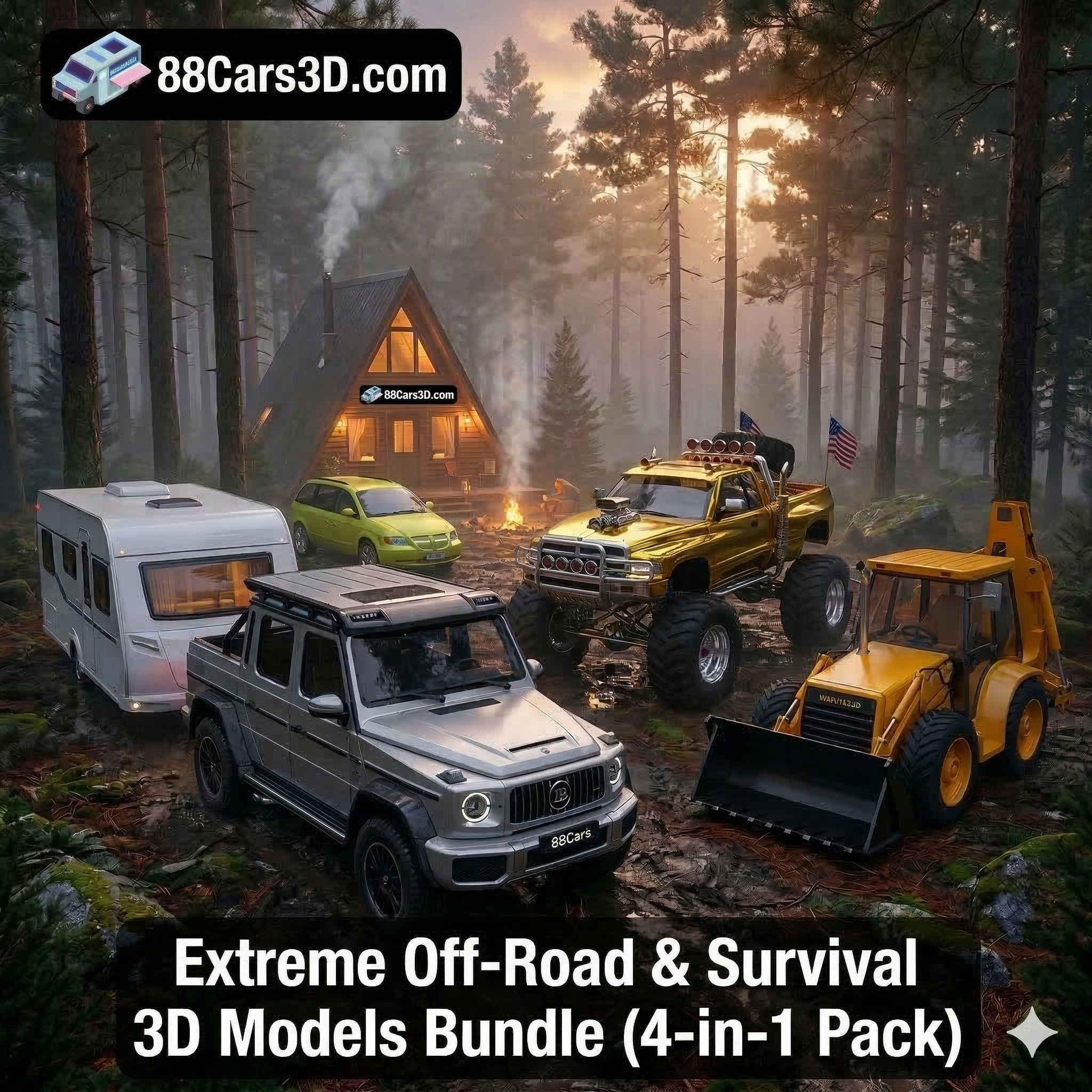
Download the Extreme Off-Road & Survival 3D Models Bundle! Includes the Brabus 800 Adventure, Dodge Ram Bigfoot, Spec Truck, and a Caravan. Save over €210 on this premium 4-in-1 off-grid vehicle pack for ArchViz and game development.
Price: $149.99
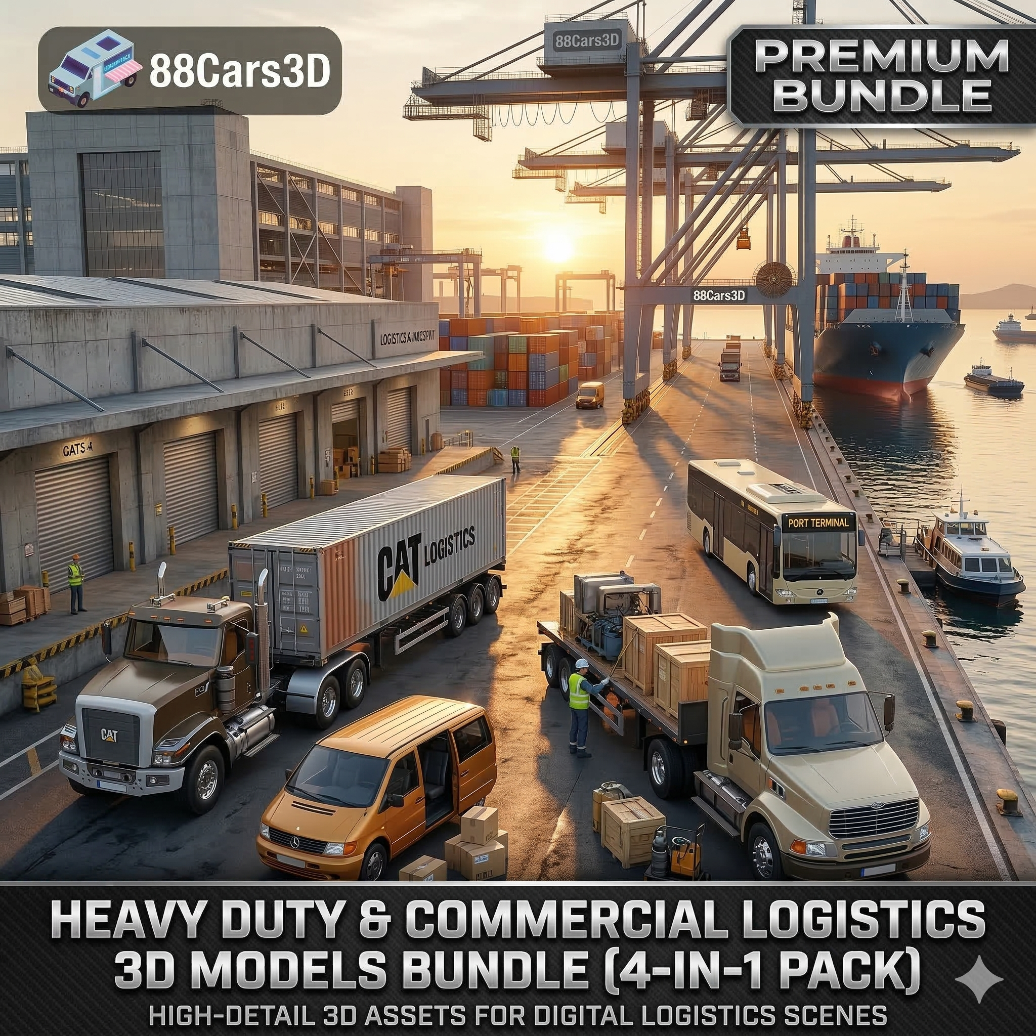
Download the Heavy Duty & Commercial Logistics 3D Models Bundle! Includes the Ford Sterling, Caterpillar CT680, Mercedes Citaro Bus, and Vito Van. Save over €130 on this massive, game-ready 4-in-1 industrial vehicle pack.
Price: $109.99

Download the Ultimate Custom Motorcycles 3D Models Bundle. Includes a Custom Chopper, Ducati 916 Café Fighter, Harley XR1200X, and BMW K100. Perfect premium props for luxury ArchViz garages. Save over €250 today!
Price: $159.99

Download the ultimate JDM Street Racing 3D Models Bundle! Includes the Nissan GT-R, Toyota Supra, Mazda RX-7, Lancer Evo IX, and Honda NSX. Save big on this highly optimized, game-ready 5-in-1 Japanese legend car pack.
Price: $129.99

Download the ultimate American Muscle & Cinematic Classics 3D Models Bundle! Includes the Dodge Charger ’68, Mustang Eleanor GT500, Camaro Z28 ’79, and a custom ’69 Mustang. Save over €240 on this game-ready, premium 4-in-1 pack.
Price: $149.99
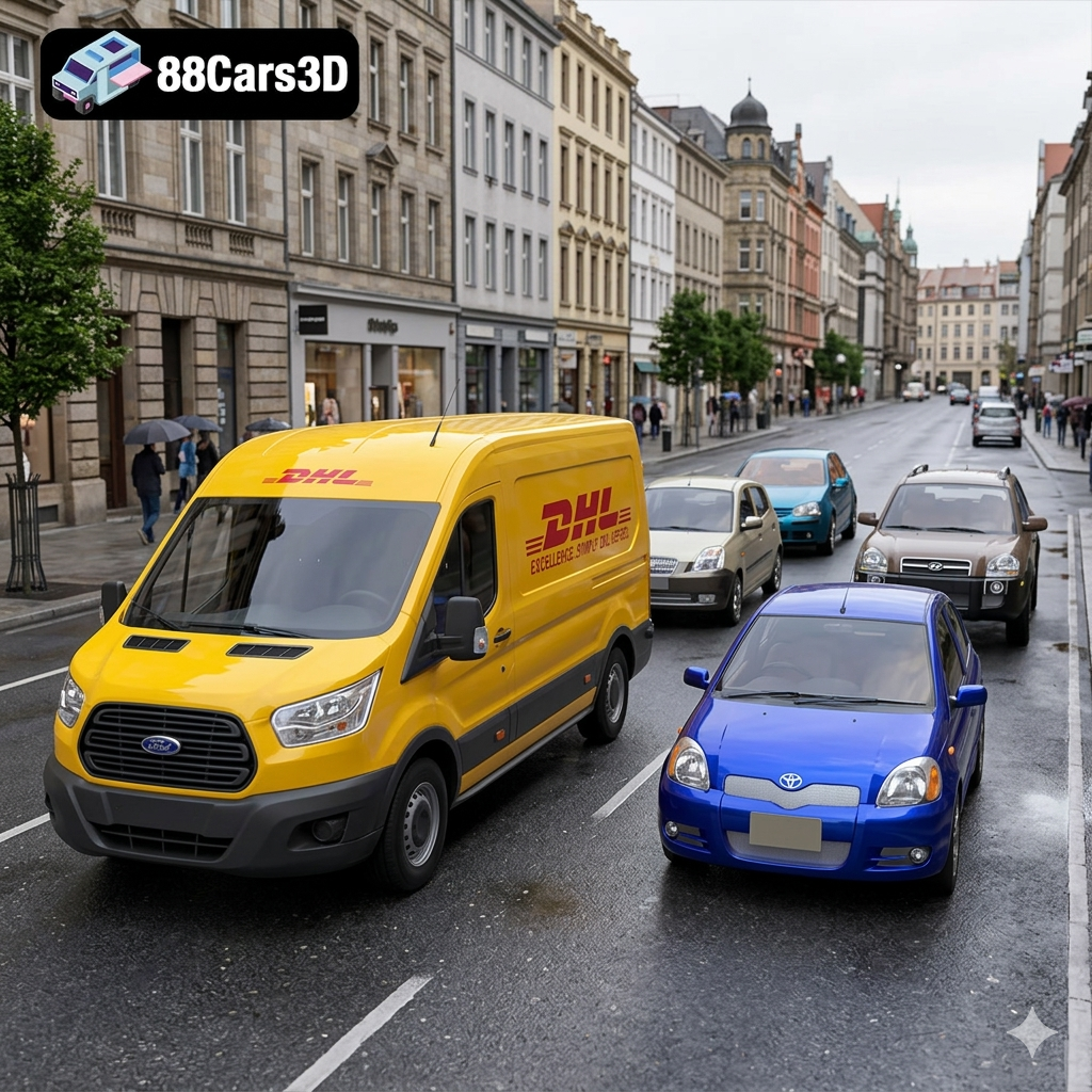
Download the Everyday City Traffic 3D Models Bundle. Includes the VW Golf, Kia Picanto, Hyundai Tucson, Toyota Yaris, and a DHL Ford Transit Van. Save big on this 5-in-1 pack, perfectly optimized for realistic ArchViz streets and game traffic.
Price: $99.99
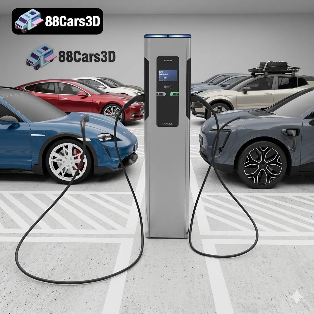
Download the Future of Mobility EV 3D Models Bundle. Includes the Volvo EX30, Tesla Model S, AVATR 11, Porsche Taycan, and a Siemens EV Charger. Save big on this highly optimized 5-in-1 pack for ArchViz and game development!
Price: $89.99

