Get 20% OFF All Premium 3D & STL Models!
“`html
So, you’ve found the perfect 3D car model, perhaps even an exquisite classic from 88cars3d.com, but it’s too large to fit on your 3D printer’s build plate. Don’t despair! Splitting large models into smaller, printable parts is a common practice in the 3D printing world. This comprehensive guide will walk you through the process of strategically dividing your model, preparing the individual parts for printing, and ultimately assembling them into a stunning finished product. You’ll learn about the software tools, techniques, and best practices necessary to tackle this challenge. We’ll cover everything from understanding the importance of strategic cuts to optimizing print settings for each individual piece. By the end of this article, you’ll have the knowledge and confidence to tackle even the most ambitious 3D car model projects.
Specifically, we’ll delve into selecting the right software, making clean and precise cuts, adding alignment features for seamless assembly, optimizing print orientation for each part, and choosing appropriate 3D printer settings. We’ll also address potential pitfalls and offer troubleshooting tips to ensure your project is a resounding success. Let’s get started!
The first step in splitting a large 3D model is selecting the appropriate software. Several options are available, each with its strengths and weaknesses. The best choice depends on your experience level, budget, and the complexity of the model. We’ll explore some popular choices and their key features for this specific task.
Autodesk Meshmixer is a free and powerful tool that’s excellent for preparing models for 3D printing, including splitting them into parts. Its cutting plane tool is particularly useful for creating clean, precise cuts. Meshmixer also allows you to add connectors or keyways for easy assembly. To use Meshmixer for splitting: Import your STL file, select “Edit” then “Plane Cut.” Position the cutting plane where you want to split the model. Choose “Keep Both” to retain both parts and then accept the cut. You can then export each part as a separate STL file. Meshmixer also allows you to hollow out parts, which can save on material and printing time. Remember to always analyze and repair your meshes within Meshmixer before exporting to ensure they are manifold and ready for slicing.
Blender, a free and open-source 3D creation suite, offers advanced modeling capabilities that are perfect for intricate splitting tasks. While it has a steeper learning curve than Meshmixer, Blender provides more control over the splitting process. You can use the “Knife Project” tool to create complex cuts based on other geometry or curves. For instance, you can define a specific panel line on a car model and use that line as the cutting path. To split the model in Blender, import the STL, enter Edit mode, and use the knife tool (K) to make your cuts. Select the vertices, edges, or faces you want to separate, then press “P” and choose “Separate by Selection.” Remember to solidify the parts to give them printable thickness. One key advantage of Blender is its ability to easily create and integrate custom connectors and alignment features directly into the model.
Autodesk Netfabb is a professional-grade software package designed for additive manufacturing workflows. It offers sophisticated tools for model repair, optimization, and splitting. Netfabb’s cutting plane tool is exceptionally precise, and its automated mesh repair features are invaluable for ensuring printability. Netfabb also has advanced features for creating lattice structures within parts to reduce weight and material usage. While Netfabb is a paid software, its robust features and industry-leading performance make it a worthwhile investment for serious 3D printing enthusiasts. Before splitting, ensure the model is oriented correctly within Netfabb. You can then use the “Cut” command to create precise divisions. Netfabb’s scripting capabilities also allow for automating repetitive splitting tasks, making it ideal for batch processing.
Before you start slicing and dicing, take a moment to plan your cuts strategically. The placement of your cuts will significantly impact the ease of printing, assembly, and the overall aesthetic of the final model. Careful planning at this stage will save you time and frustration later.
One of the primary goals when splitting a model is to minimize the need for support structures. Overhanging features require supports, which can be difficult to remove and leave behind unsightly marks. Consider splitting the model along natural lines that reduce overhangs. For example, separate the roof of a car from the body to allow printing both pieces with minimal supports facing downward. Another technique is to analyze the model’s geometry in your slicer software to identify areas that will require extensive support and then adjust the cut lines accordingly. Consider the print orientation when evaluating support needs.
Whenever possible, try to position your cuts along existing panel lines, seams, or other features of the car model. This will help to conceal the cut lines after assembly, making them less noticeable. For example, the separation between the car’s body and the bumpers is a natural choice. Analyze the model carefully to identify existing features that can be used as camouflage for your cuts. When downloading models from marketplaces such as 88cars3d.com, pay close attention to the existing geometry and identify potential cutting locations early in the process.
Think about how you will assemble the parts after printing. Simple, interlocking joints will make the assembly process much easier. Avoid creating small, fragile parts that will be difficult to handle and glue together. Consider adding alignment features, such as pegs and holes, to ensure precise alignment during assembly. The complexity of the assembly should be balanced against the number of parts. Fewer parts typically mean less assembly but potentially more complex printing (and more support material). Carefully evaluate this tradeoff during the planning phase.
Alignment features are critical for ensuring that the individual parts of your 3D car model fit together perfectly. These features help to guide the parts into the correct position and prevent misalignment during gluing or other assembly methods. Adding these features can drastically improve the final appearance of your model.
The most common type of alignment feature is a peg and hole system. Create small cylindrical pegs on one part of the model and corresponding holes on the mating part. The pegs should be slightly smaller than the holes to allow for some tolerance and prevent binding. Typically, a tolerance of 0.1-0.2mm is sufficient. In Meshmixer, you can use the “Append” tool to add cylinders as pegs and then use Boolean operations to subtract cylinders to create holes. The placement of pegs and holes is important; use at least two, preferably three, to prevent rotation of the parts relative to each other. A triangular arrangement is often ideal.
Keyways and slots are another excellent option for alignment, especially for larger parts. These features involve creating a protruding key on one part that fits into a corresponding slot on the mating part. Keyways and slots provide a more robust alignment system than pegs and holes, particularly when dealing with parts that may experience stress or movement. Design the keyways and slots to be slightly tapered to facilitate easy insertion. Ensure the keyway’s depth is sufficient to provide adequate alignment but not so deep that it weakens the surrounding material.
For a more advanced approach, consider integrating connectors directly into the model’s geometry. This can involve creating snap-fit connectors or dovetail joints that lock the parts together without the need for glue. Designing integrated connectors requires more advanced modeling skills, but the result is a seamless and robust assembly. When designing snap-fit connectors, ensure the snap feature has sufficient flexibility to allow for easy insertion and removal but also enough strength to hold the parts together securely. 3D printing tolerances are crucial here; test print a small section of the connector before integrating it into the entire model.
Once you’ve split your model and added alignment features, the next step is to optimize the print orientation and settings for each individual part. The optimal orientation and settings will vary depending on the geometry of each part, the type of 3D printer you’re using (FDM or resin), and the desired print quality.
The orientation in which you print each part will significantly impact its strength and the level of detail that can be achieved. Orient parts to minimize overhangs and the need for support structures. However, also consider the direction of stresses the part will experience after assembly. Printing a part with the grain of the print layers aligned with the direction of stress will result in a stronger part. For detailed features, orient the part so that the finest details are facing upwards. This will allow the printer to capture those details with maximum precision. Experiment with different orientations in your slicer software to find the best balance between support requirements, strength, and detail.
The slicing parameters you use will depend on whether you’re using an FDM (Fused Deposition Modeling) or resin printer. For FDM printers, key parameters include layer height, infill density, print speed, and nozzle temperature. A lower layer height will result in finer details but will also increase printing time. A higher infill density will increase the strength of the part but will also increase material usage. Experiment with different settings to find the best balance between print quality, strength, and printing time. For resin printers, key parameters include layer exposure time, lift speed, and bottom layer count. The exposure time determines how long each layer is exposed to the UV light. A longer exposure time will result in stronger parts but can also lead to over-curing. Optimize these settings based on the specific resin you’re using and the recommendations of the resin manufacturer.
Even with careful orientation, some parts may still require support structures. The type of support structure you use and the way it’s generated can significantly impact the quality of the final print. In Cura, for example, you can choose between different support patterns, such as zigzag, lines, and concentric. For delicate features, use tree supports, which provide more targeted and less intrusive support. Adjust the support density and overhang angle to optimize support strength and ease of removal. When using soluble supports (e.g., PVA), ensure that the interface between the support and the part is minimized to prevent adhesion issues. After printing, carefully remove the supports using appropriate tools, such as pliers, cutters, and sandpaper. Take your time and avoid damaging the part.
The final step in bringing your 3D car model to life is post-processing and assembly. Post-processing involves cleaning up the printed parts, removing support structures, and smoothing the surfaces. Assembly involves joining the individual parts together to create the finished model.
Carefully remove support structures using pliers, cutters, or a sharp knife. Take your time and avoid damaging the parts. For difficult-to-reach areas, consider using specialized tools designed for support removal. After removing the supports, use sandpaper to smooth any remaining rough edges or support marks. Start with a coarse grit sandpaper and gradually move to finer grits to achieve a smooth surface. For resin prints, consider curing the parts further under UV light to ensure they are fully hardened.
To achieve a professional-looking finish, sand the parts thoroughly to remove any layer lines or imperfections. Apply a primer to the parts to create a smooth and uniform surface for painting. Choose a primer that is compatible with the material you’re using. After the primer has dried, sand it lightly with a fine-grit sandpaper. Apply several thin coats of paint, allowing each coat to dry completely before applying the next. Use high-quality paints designed for model making. Consider using an airbrush for a smoother and more even finish. After the paint has dried, apply a clear coat to protect the paint and add a glossy or matte finish.
Assemble the parts using glue, screws, or other fasteners. Choose a glue that is appropriate for the material you’re using. Cyanoacrylate (super glue) is a good option for most plastics. Epoxy is a stronger adhesive but requires more time to cure. Align the parts carefully using the alignment features you added earlier. Use clamps or tape to hold the parts together while the glue is drying. For larger parts, consider using screws or other mechanical fasteners to provide additional strength and stability. Platforms like 88cars3d.com offer print-ready STL files that are designed with assembly in mind, potentially reducing the need for extensive post-processing.
Even with careful planning and execution, you may encounter some common issues when splitting and printing large 3D models. Here are some troubleshooting tips to help you overcome these challenges.
One of the most common issues is mesh errors, such as holes, gaps, and non-manifold geometry. These errors can prevent the model from being printed correctly. Use mesh repair tools in Meshmixer, Netfabb, or other software to identify and fix these errors. Non-manifold geometry occurs when edges are shared by more than two faces, which is impossible in the real world. Mesh repair tools can automatically correct these errors by adding or removing faces and edges.
Poor bed adhesion and warping are common problems when printing large parts, especially with FDM printers. Ensure that your print bed is clean and level. Use a bed adhesive, such as glue stick, hairspray, or painter’s tape, to improve adhesion. Increase the bed temperature to help the plastic adhere to the bed. Enclose the printer to maintain a consistent temperature and prevent warping. For ABS prints, an enclosure is essential. Consider adding a brim or raft to the print to increase the surface area in contact with the bed and improve adhesion.
Support structure failures can occur if the supports are not strong enough or if they are not properly anchored to the bed. Increase the support density or thickness to make them stronger. Use a larger support interface to improve adhesion to the part. Ensure that the supports are properly connected to the bed. Avoid printing supports directly on top of other supports, as this can create weak points. Experiment with different support patterns to find the one that works best for your printer and material.
Splitting large 3D car models into printable parts is a rewarding process that opens up a world of possibilities. By carefully planning your cuts, adding alignment features, optimizing print settings, and mastering post-processing techniques, you can create stunning, high-quality models that would otherwise be impossible to print on a smaller build plate. Remember to choose the right software, consider minimizing supports and concealing cut lines, and always prioritize a well-thought-out assembly strategy.
Don’t be afraid to experiment and learn from your mistakes. 3D printing is a constantly evolving field, and there’s always something new to discover. With practice and patience, you’ll become a master of model splitting and 3D printing. Now, go forth and create your dream car model! Consider browsing the extensive collection of printable car models at 88cars3d.com for your next project.
“`
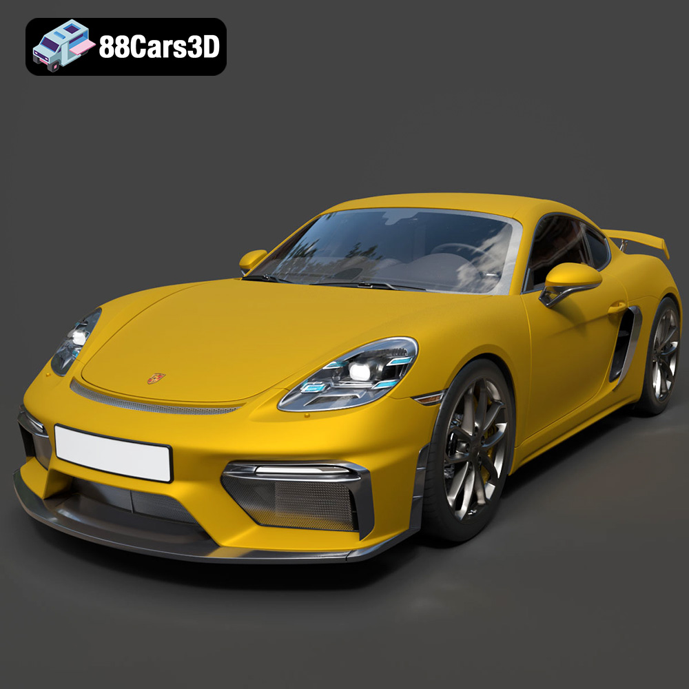
Texture: Yes | Material: Yes
Download the highly detailed, game-ready Porsche 718 Cayman GT4 2020 3D Model. Features an aggressive fixed rear wing, distinctive side air intakes, and a track-focused stance. Includes .blend, .fbx, .obj, .glb, .stl, .ply, .unreal, and .max formats for game development, AR/VR, and rendering.
Price: $19.99

Texture: Yes | Material: Yes
Download the highly detailed, game-ready Polestar 2 2020 3D Model. Features minimalist Scandinavian fastback styling, pixel LED lighting, and an accurate electric vehicle profile. Includes .blend, .fbx, .obj, .glb, .stl, .ply, .unreal, and .max formats for game development, AR/VR, and rendering.
Price: $19.99
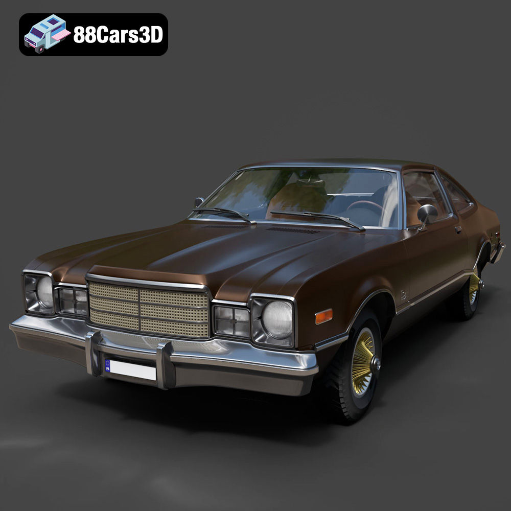
Texture: Yes | Material: Yes
Download the highly detailed, game-ready Plymouth Volare Coupe 1977 3D Model. Features classic F-body styling, detailed chrome trim, and an accurate vintage interior. Includes .blend, .fbx, .obj, .glb, .stl, .ply, .unreal, and .max formats for game development, AR/VR, and rendering.
Price: $19.99
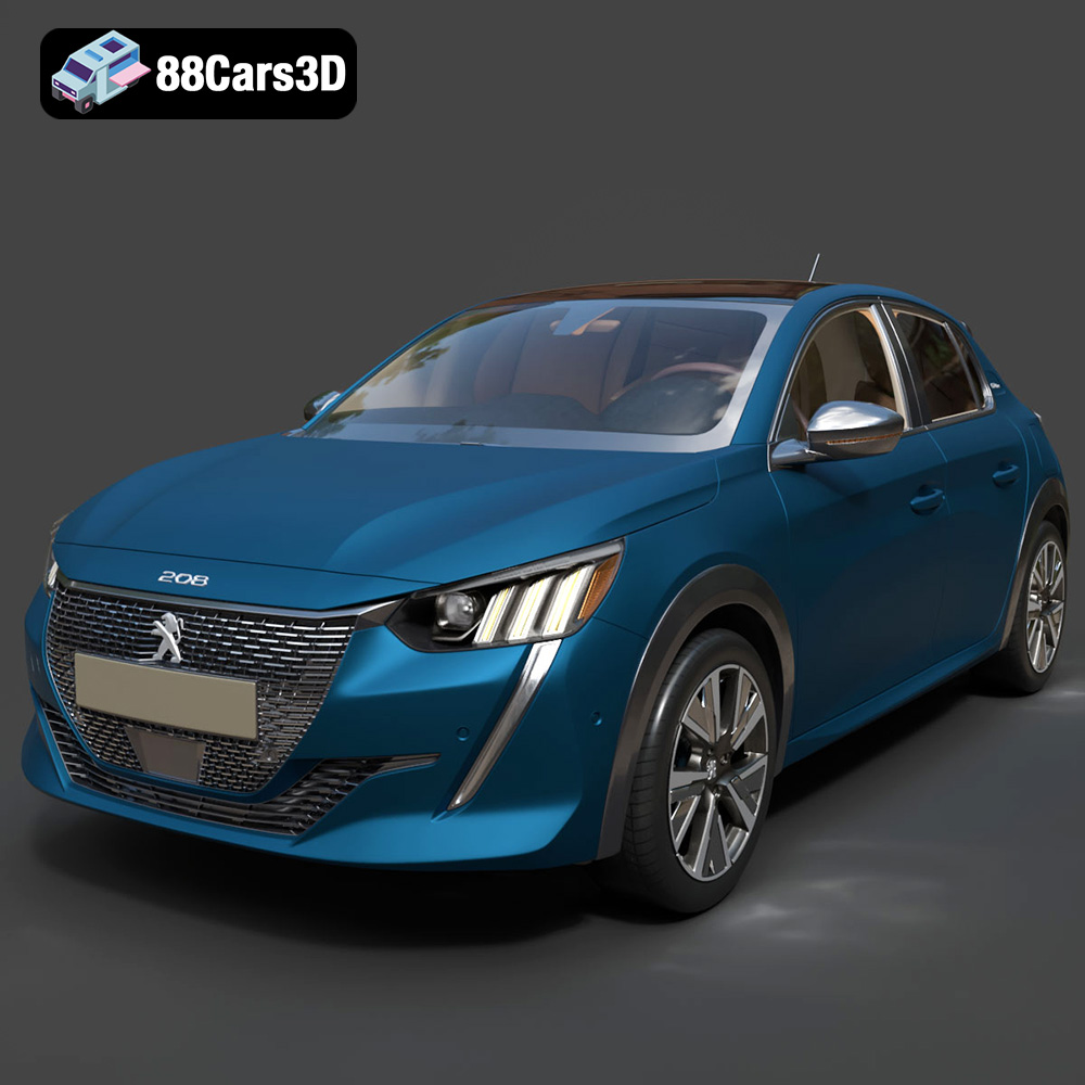
Texture: Yes | Material: Yes
Download the highly detailed, game-ready Peugeot 208 2020 3D Model. Features aggressive ‘fang’ LED DRLs, sporty hatchback proportions, and aerodynamic alloy wheels. Includes .blend, .fbx, .obj, .glb, .stl, .ply, .unreal, and .max formats for game development, AR/VR, and rendering.
Price: $19.99

Texture: Yes | Material: Yes
Download the highly detailed, game-ready MV Agusta Brutale 1090 R 3D Model. Features an exposed trellis frame, distinctive teardrop headlight, and muscular naked bike styling. Includes .blend, .fbx, .obj, .glb, .stl, .ply, .unreal, and .max formats for game development, AR/VR, and rendering.
Price: $19.99
Texture: Yes | Material: Yes
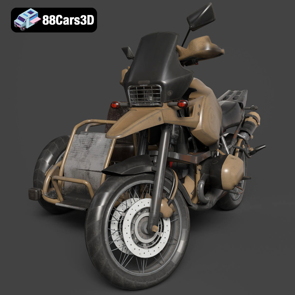
Download the highly detailed, game-ready Custom Off-Road BMW R1150GS Adventure Sidecar 3D Model. Features rugged all-terrain suspension, an attached passenger sidecar, and off-road knobby tires. Includes .blend, .fbx, .obj, .glb, .stl, .ply, .unreal, and .max formats for game development, AR/VR, and rendering.
Price: $19.99

Texture: Yes | Material: Yes
Download the highly detailed, game-ready Mitsubishi Outlander GT 2010 3D Model. Features the aggressive Lancer-inspired front grille, accurate exterior styling, and high-fidelity alloy wheels. Includes .blend, .fbx, .obj, .glb, .stl, .ply, .unreal, and .max formats for game development, AR/VR, and rendering.
Price: $19.99
Texture: Yes | Material: Yes
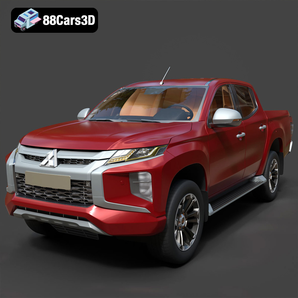
Download the highly detailed, game-ready Mitsubishi L200 Crew Cab 2019 3D Model. Features the iconic Dynamic Shield front fascia, rugged cargo bed, and a spacious crew cab interior. Includes .blend, .fbx, .obj, .glb, .stl, .ply, .unreal, and .max formats for game development, AR/VR, and rendering.
Price: $19.99
Texture: Yes | Material: Yes
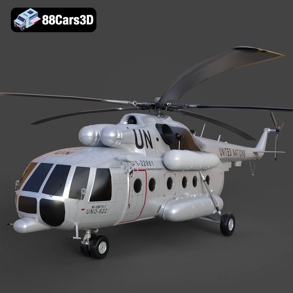
Download the highly detailed, game-ready Mil Mi-8MTV-UN 3D Model. Features the iconic United Nations white livery, detailed twin turboshaft engines, and fully articulated rotor assemblies. Includes .blend, .fbx, .obj, .glb, .stl, .ply, .unreal, and .max formats for game development, AR/VR, and rendering.
Price: $19.99
Texture: Yes | Material: Yes
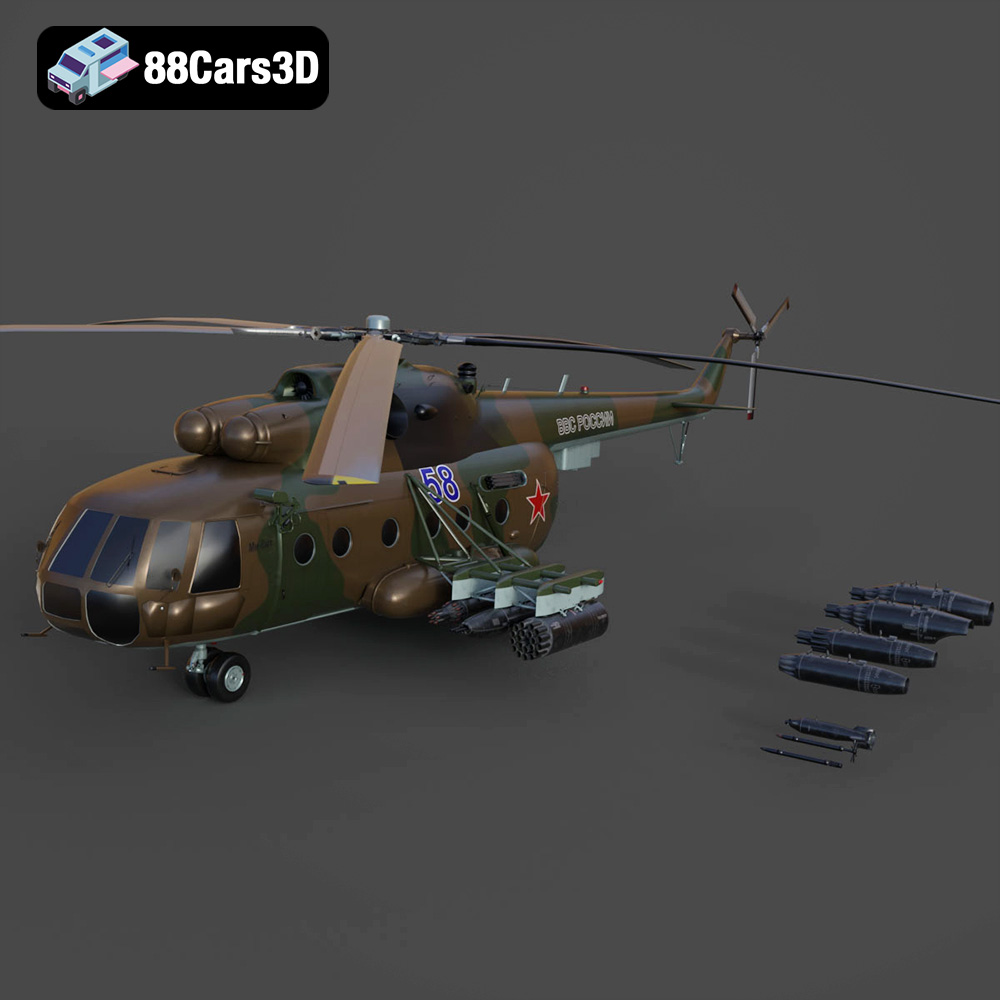
Download the highly detailed, game-ready Mil Mi-8MT Helicopter 3D Model. Features twin-turbine engine housings, a detailed 5-blade main rotor, and authentic cockpit instrumentation. Includes .blend, .fbx, .obj, .glb, .stl, .ply, .unreal, and .max formats for game development, AR/VR, and rendering.
Price: $19.99

