Get 20% OFF All Premium 3D & STL Models!
“`html
The world of 3D printing offers incredible opportunities for hobbyists, engineers, and model collectors alike. Whether you’re printing scale models of classic cars or prototyping automotive components, the quality of your final print hinges on the integrity of the STL file. Often, downloaded STL files – even those from reputable sources – can contain imperfections that lead to print failures or subpar results. Fortunately, Blender, a powerful and free 3D modeling software, provides a robust set of tools for cleaning up STL files before sending them to your 3D printer. This article will guide you through the process of identifying and correcting common issues in STL files using Blender, ensuring your 3D printed car models from platforms like 88cars3d.com come out looking their best.
In this comprehensive guide, you’ll learn about STL file structure, common mesh errors, how to import and inspect STL files in Blender, and the various techniques for repairing and optimizing your models. We’ll cover everything from filling holes and fixing non-manifold geometry to smoothing surfaces and reducing file size. By mastering these techniques, you’ll be able to confidently prepare your STL files for 3D printing and achieve professional-quality results every time.
STL (Stereolithography) files are the standard format for 3D printing. They represent the surface geometry of a 3D object using a collection of triangles. While simple in concept, STL files can often contain errors that cause problems during 3D printing. Understanding these errors is the first step in effectively cleaning up your models.
An STL file essentially describes the outer surface of a 3D object using a mesh of interconnected triangles. Each triangle is defined by three vertices (points in 3D space) and a normal vector (indicating the direction the triangle is facing). Problems can arise when these triangles are not properly connected, oriented, or when the mesh contains self-intersections.
Several types of errors commonly plague STL files. These include:
These errors, if left uncorrected, can lead to print failures, weak points in the printed object, or a rough and inaccurate final product. Therefore, thoroughly inspecting and cleaning up your STL files is a critical step in the 3D printing workflow.
Blender provides a user-friendly interface for importing and inspecting STL files. Its visual tools make it easy to identify the various mesh errors that can compromise your print quality. This section will guide you through the import process and show you how to use Blender’s features to spot potential problems.
To import an STL file into Blender, simply go to File > Import > Stl (.stl). Navigate to the location of your STL file and select it. Once imported, the model will appear in the 3D viewport.
Blender offers several tools for inspecting the mesh:
By using these tools, you can systematically examine your STL file for errors and pinpoint areas that require cleaning up. Paying close attention to these details during the inspection phase will save you time and frustration in the long run.
Non-manifold geometry is one of the most common and problematic errors in STL files. It essentially means that the mesh doesn’t represent a physically possible object, which can confuse slicing software and lead to printing errors. Blender offers several tools to address this issue.
As mentioned earlier, the Mesh > Analyze > Make Manifold tool can highlight non-manifold areas. While it doesn’t automatically fix everything, it’s a good starting point. After running the tool, examine the highlighted regions carefully. Often, the problem is caused by overlapping faces or internal geometry. You may need to manually delete problematic faces (select the faces in Edit Mode and press ‘X’ then ‘Faces’) and then recreate the geometry.
Often, non-manifold geometry results from very closely spaced vertices that are not perfectly aligned. The “Merge by Distance” tool can automatically snap these vertices together, effectively welding them and creating a more robust mesh. In Edit Mode, select all vertices (press ‘A’) and then go to Mesh > Clean Up > Merge by Distance. Adjust the ‘Distance’ value in the bottom-left corner of the viewport. Start with a small value (e.g., 0.001mm) and increase it gradually until the problem areas are resolved. Be careful not to merge vertices that should remain separate, as this can distort the model.
In some cases, manual correction is necessary. This involves using Blender’s modeling tools (e.g., extrude, bridge edges, fill) to recreate the missing or incorrect geometry. This can be time-consuming but is often the most effective way to ensure a clean and accurate mesh. For example, if you have a small hole, you can select the surrounding edges, press ‘F’ to fill the hole with a face, and then adjust the vertices as needed to match the surrounding geometry. Patience and attention to detail are key when performing manual mesh repair.
Inverted normals and holes can both lead to significant printing issues. Inverted normals can cause the slicer to interpret the model inside-out, while holes obviously create gaps in the printed object. Fortunately, Blender provides straightforward tools for correcting these issues.
If you’ve identified faces with inverted normals using the “Face Orientation” overlay, you can easily flip them. In Edit Mode, select the faces with incorrect normals and then go to Mesh > Normals > Flip. This will reverse the direction of the normals, ensuring they point outward. Alternatively, you can select Mesh > Normals > Recalculate Outside. Blender will attempt to automatically determine the correct orientation of the normals based on the surrounding geometry. This is often a quicker solution, but it’s important to double-check the results to ensure all normals are correctly oriented.
To fill holes in the mesh, select the edges surrounding the hole in Edit Mode. If the hole is relatively small and simple, pressing ‘F’ will often automatically fill it with a new face. For more complex holes, you may need to use the “Bridge Edge Loops” tool (Edge > Bridge Edge Loops) to create a smooth transition between the existing geometry and the new face. You may also need to manually create new faces and adjust their vertices to properly close the hole.
Sometimes there may only be a gap between faces. These can be easily closed by selecting two vertices in Edit Mode and pressing ‘F’ to create a new edge. Alternatively, select three edges/vertices that define the outline of a face and press ‘F’ to create a new face.
While a high level of detail is desirable, excessively dense meshes can slow down slicing and printing. Furthermore, rough surfaces can detract from the final appearance of your 3D printed car models. Blender offers tools for optimizing mesh density and smoothing surfaces, ensuring a balance between detail and print performance.
The “Decimate” modifier is a powerful tool for reducing the polygon count of a mesh while preserving its overall shape. Add a “Decimate” modifier to your object in the Modifiers panel. There are several decimation methods available:
Experiment with different decimation methods and settings to find the optimal balance between reducing the polygon count and preserving the desired level of detail. Remember to apply the modifier once you’re satisfied with the result. It is best practice to duplicate the object first and apply the modifier to the duplicate as decimation is a destructive process and not easily reversible.
To smooth the surfaces of your model, you can use the “Shade Smooth” option (Object > Shade Smooth). This will interpolate the surface normals, creating a smoother appearance. For more pronounced smoothing, you can add a “Subdivision Surface” modifier. This modifier subdivides the mesh, adding more polygons and creating a smoother surface. Be careful not to over-subdivide the mesh, as this can significantly increase the polygon count. Combine the “Shade Smooth” option and “Subdivision Surface” modifier to find the optimal level of smoothness for your model.
The “Remesh” modifier can rebuild the entire mesh with a more uniform topology. This can be useful for simplifying complex meshes or for creating a more consistent surface for sculpting. The “Voxel” remesher is a popular option. Adjust the “Voxel Size” parameter to control the density of the remeshed mesh. Smaller voxel sizes result in higher detail but also increase the polygon count.
Once you’ve cleaned and optimized your STL file in Blender, the final step is to export it in a format suitable for your 3D printer’s slicing software. This section covers the export process and provides some tips for preparing the file for slicing.
To export your model as an STL file, go to File > Export > Stl (.stl). In the export settings, make sure the “Selection Only” option is unchecked if you want to export the entire scene. Choose a suitable file name and location and click “Export STL.”
After exporting, it’s a good practice to re-import the STL file into Blender or another 3D viewing software to verify that the exported file is correct and doesn’t contain any unexpected errors. This can help you catch any issues that may have arisen during the export process.
Before slicing, carefully consider the orientation of your model on the print bed. The optimal orientation can minimize the need for support structures, improve surface finish, and reduce print time. Experiment with different orientations in your slicing software to find the best solution for your specific model. For printable car models from marketplaces such as 88cars3d.com, consider the flattest side as the base, or the side that requires the least support material.
When slicing your STL file, pay attention to the following parameters:
Even after meticulously cleaning your STL file, you might still encounter some printing issues. Here’s a troubleshooting guide for some common problems and how to address them:
If the first layer isn’t sticking to the bed, try the following:
Warping occurs when the corners of the print lift off the bed. This is often caused by temperature differences between the print and the surrounding environment.
Stringing is caused by molten filament oozing from the nozzle during travel moves.
Layer shifting occurs when the printer head shifts unexpectedly during printing.
By systematically addressing these common printing issues, you can ensure successful and high-quality 3D prints of your car models, regardless of their origin. These techniques, combined with well-prepared STL files from sources like 88cars3d.com, set the stage for exceptional 3D printing results.
Cleaning up STL files with Blender is an essential skill for anyone involved in 3D printing, especially when dealing with intricate models like car replicas. By understanding the structure of STL files, identifying common mesh errors, and mastering Blender’s repair tools, you can significantly improve the quality and reliability of your prints. From fixing non-manifold geometry and correcting inverted normals to optimizing mesh density and smoothing surfaces, the techniques outlined in this guide will empower you to confidently prepare your STL files for 3D printing.
Remember to always inspect your STL files thoroughly before slicing and to verify the results after exporting. Experiment with different settings and techniques to find the optimal workflow for your specific printer and material. Whether you are printing for hobbyist collections, model making, or prototyping, a clean STL file is the foundation for success. So, download Blender, grab some STL files, and start practicing. With a little effort, you’ll be producing professional-quality 3D printed car models in no time. The first step is often the hardest, but with these tools in your arsenal, you’re well-equipped to overcome any challenge the world of 3D printing throws your way!
“`

Texture: Yes | Material: Yes
Download the highly detailed, game-ready Ferrari J50 2017 3D Model. Features aggressive aerodynamic styling, twin-turbo V8 engine details, and targa top design. Includes .blend, .fbx, .obj, .glb, .stl, .ply, .unreal, and .max formats for game development, AR/VR, and rendering.
Price: $19.99
Texture: Yes | Material: Yes
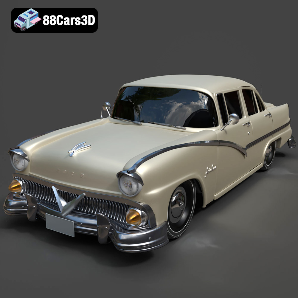
Download the highly detailed, game-ready Ford Fairlin 3D Model. Features iconic classic styling, sweeping bodylines, and an accurate vintage interior. Includes .blend, .fbx, .obj, .glb, .stl, .ply, .unreal, and .max formats for game development, AR/VR, and rendering.
Price: $19.99
Texture: Yes | Material: Yes
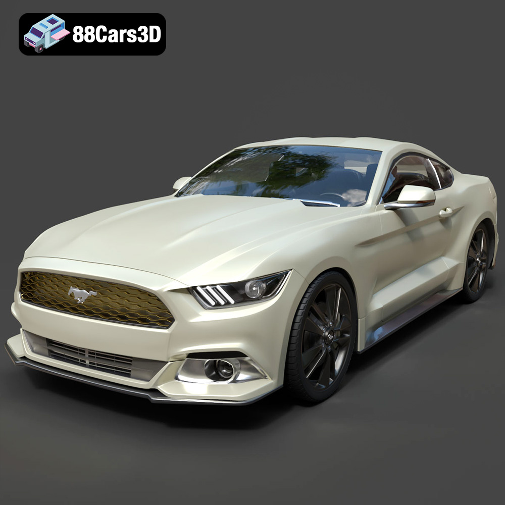
Download the highly detailed, game-ready Ford Mustang GT 3D Model. Features aggressive muscle car styling, a highly detailed V8 engine bay, and accurate interior cockpit. Includes .blend, .fbx, .obj, .glb, .stl, .ply, .unreal, and .max formats for game development, AR/VR, and rendering.
Price: $19.99

Texture: Yes | Material: Yes
Download the highly detailed, game-ready Renault Megane CC 2011 3D Model. Features an accurately modeled folding glass roof, sleek aerodynamic body lines, and a detailed interior. Includes .blend, .fbx, .obj, .glb, .stl, .ply, .unreal, and .max formats for game development, AR/VR, and rendering.
Price: $19.99

Texture: Yes | Material: Yes
Download the highly detailed, game-ready Ford GT 2005 3D Model. Features signature aerodynamic bodylines, mid-mounted supercharged V8 detailing, and iconic racing stripes. Includes .blend, .fbx, .obj, .glb, .stl, .ply, .unreal, and .max formats for game development, AR/VR, and rendering.
Price: $19.99
Texture: Yes | Material: Yes
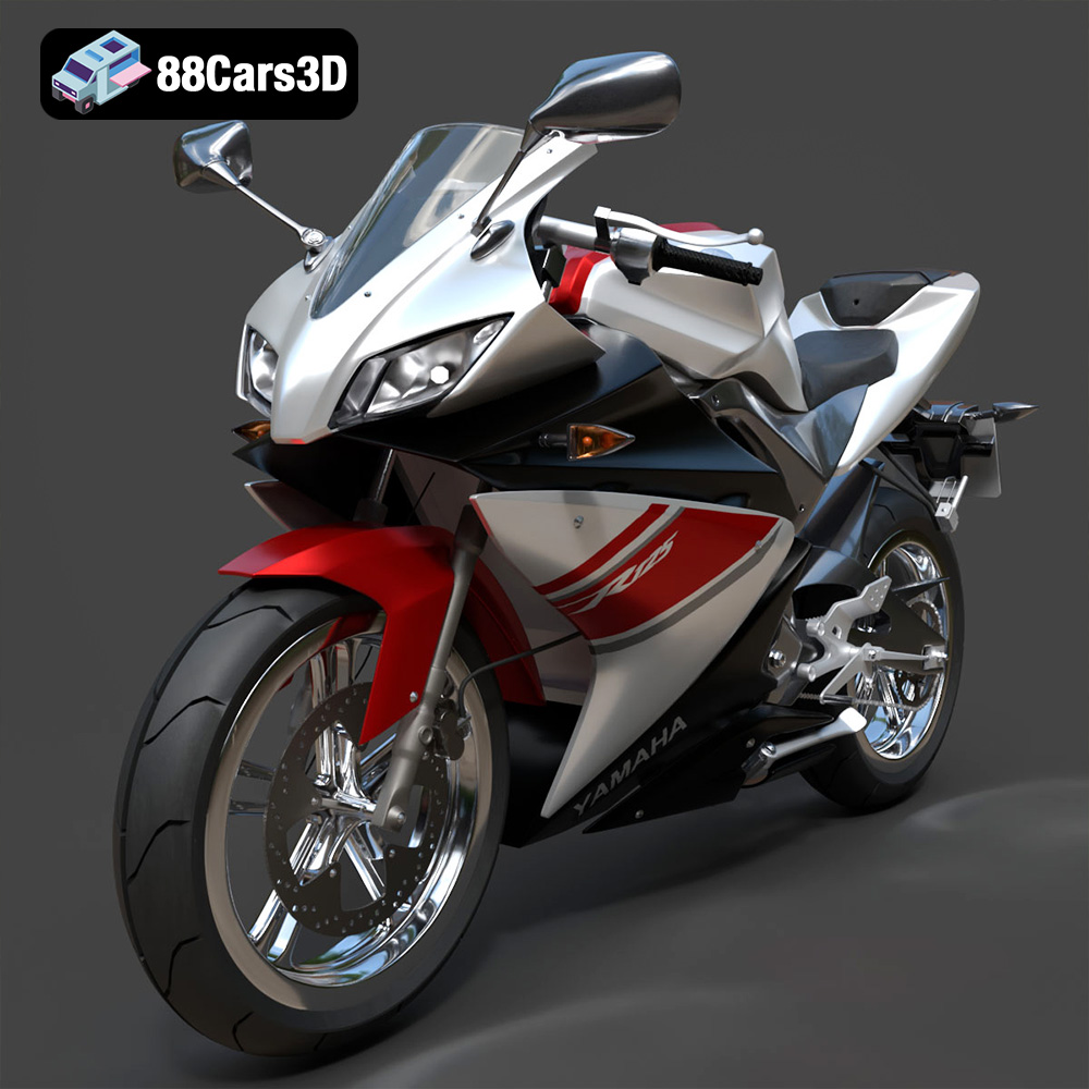
Download the highly detailed, game-ready Yamaha YZF-R125 EU 3D Model. Features an aggressive aerodynamic fairing, twin LED headlights, and a detailed 125cc engine block. Includes .blend, .fbx, .obj, .glb, .stl, .ply, .unreal, and .max formats for game development, AR/VR, and rendering.
Price: $19.99
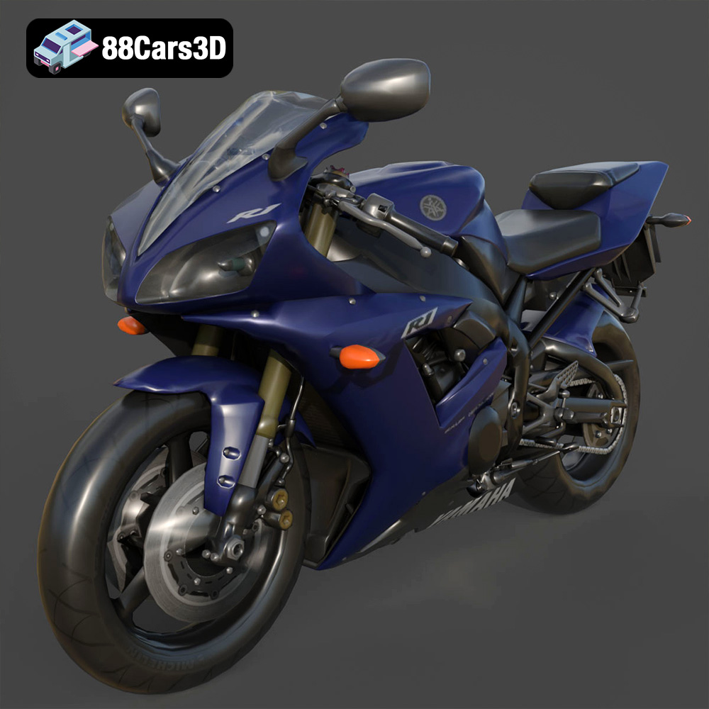
Texture: Yes | Material: Yes
Download the highly detailed, game-ready Yamaha R1 3D Model. Features aggressive aerodynamic fairings, a detailed crossplane inline-4 engine, and track-focused suspension geometry. Includes .blend, .fbx, .obj, .glb, .stl, .ply, .unreal, and .max formats for game development, AR/VR, and rendering.
Price: $19.99
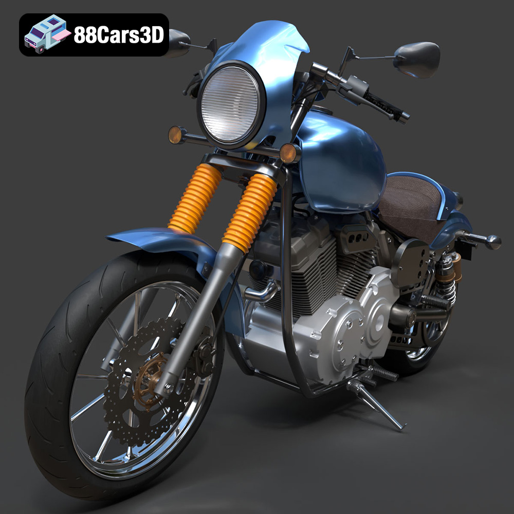
Texture: Yes | Material: Yes
Download the highly detailed, game-ready Yamaha XV950 Racer 3D Model. Features an aggressive cafe-racer front cowl, detailed air-cooled V-twin engine, and classic retro styling. Includes .blend, .fbx, .obj, .glb, .stl, .ply, .unreal, and .max formats for game development, AR/VR, and rendering.
Price: $19.99

Texture: Yes | Material: Yes
Download the highly detailed, game-ready Volvo VNL Tractor Truck 2002 3D Model. Features iconic aerodynamic styling, detailed fifth-wheel coupling, and heavy-duty chassis. Includes .blend, .fbx, .obj, .glb, .stl, .ply, .unreal, and .max formats for game development, AR/VR, and rendering.
Price: $39.99
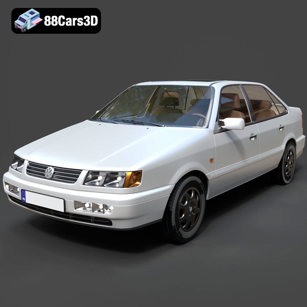
Texture: Yes | Material: Yes
Download the highly detailed, game-ready Volkswagen Passat Mk4 B4 Sedan 1993 3D Model. Features accurate 90s sedan styling, detailed front grille-less fascia, and a classic interior setup. Includes .blend, .fbx, .obj, .glb, .stl, .ply, .unreal, and .max formats for game development, AR/VR, and rendering.
Price: $39.99

