Get 20% OFF All Premium 3D & STL Models!
“`html
3D printing has revolutionized manufacturing, design, and hobbyist projects. The process begins with a digital 3D model, often in STL (Stereolithography) format. While many models are print-ready, downloaded STL files, especially those sourced from various online repositories, can contain imperfections that lead to print failures. These imperfections can range from non-manifold geometry to internal faces, and flipped normals. This is particularly relevant when printing detailed models, such as printable car models obtained from platforms like 88cars3d.com. A clean STL file is crucial for successful 3D printing, regardless of whether you’re using FDM or resin printing. In this comprehensive guide, we’ll delve into how to use Blender, a powerful and free open-source 3D creation suite, to effectively clean up STL files and prepare them for flawless 3D prints. We’ll cover essential techniques, tools, and best practices to ensure your models are ready for the printer bed. You’ll learn about identifying common STL issues, applying corrective measures in Blender, and exporting a clean, printable file. This guide will also touch upon optimizing your mesh for different printing methods and material considerations.
Dirty STL files can lead to a host of printing problems, including failed prints, weak structures, and poor surface finish. Understanding why these problems occur is the first step in effective cleanup.
Blender provides a comprehensive suite of tools for identifying and resolving these issues. While dedicated mesh repair software exists (Netfabb, Meshmixer), Blender offers a powerful and versatile alternative, especially for users already familiar with its interface. Many operations can be completed using Blender’s sculpt mode, edit mode, and modifiers.
The first step is to import the STL file into Blender and thoroughly inspect it for potential issues. This involves using Blender’s various tools to visualize the mesh and identify problem areas. Whether you’re working with a finely detailed car model downloaded from 88cars3d.com or a simple geometric shape, this process is crucial.
To import an STL file into Blender, navigate to File > Import > Stl (.stl). Choose the desired STL file from your directory. Once imported, the model will appear in the 3D viewport. Initial inspection should focus on the overall appearance, looking for obvious holes, gaps, or distortions.
Blender offers several overlays that are vital for identifying mesh issues. Access these through the “Viewport Overlays” dropdown menu in the top-right corner of the 3D Viewport. Key overlays include:
Efficient navigation within the 3D viewport is essential for detailed inspection. Use the middle mouse button to rotate the view, shift + middle mouse button to pan, and the mouse wheel to zoom. Familiarize yourself with these controls to thoroughly examine the model from all angles. Inspect for any holes, gaps, intersecting faces, or distorted areas.
Non-manifold geometry is a common issue in STL files and can cause significant problems during slicing and printing. This section focuses on identifying and correcting these issues using Blender’s tools. Addressing these issues is crucial for creating a watertight, printable model.
Blender has a built-in tool specifically for selecting non-manifold edges and vertices. To use it, switch to Edit Mode (Tab key), select the entire mesh (A key), then navigate to Select > Select All by Trait > Non Manifold. This will highlight all problematic areas in orange. Zoom in to examine these areas closely.
Once non-manifold edges are selected, you can use various tools to fix them. A common technique is to bridge gaps between edges. Select two opposing edges and press “F” to create a new face between them. For larger holes, consider using the “Fill” tool (Alt+F) to automatically generate faces within the selected boundary.
Example Workflow:
The Solidify modifier can sometimes help to resolve minor non-manifold issues, especially thin walls. Apply the modifier with a small thickness value (e.g., 0.1mm or 0.2mm) and check if it seals any small gaps. After applying the modifier, carefully inspect the mesh again to ensure no new issues have been introduced.
Flipped normals and internal faces can also lead to printing problems. Flipped normals cause the slicer to interpret the model’s inside as its outside, resulting in hollow or inverted prints. Internal faces add unnecessary complexity and can interfere with slicing. Identifying and correcting these issues is essential for producing accurate and structurally sound 3D prints.
As mentioned earlier, the “Face Orientation” overlay highlights flipped normals in red. To correct them, select the faces with incorrect orientation in Edit Mode and press Shift+N (Recalculate Normals). If the normals are still incorrect, try selecting all faces and pressing Alt+N > Flip to manually invert the normals. Check the “Face Orientation” overlay again to ensure all faces are now blue (pointing outwards).
Troubleshooting Flipped Normals:
Identifying internal faces can be tricky. One approach is to use the “Select > Select All by Trait > Interior Faces” tool (available in Edit Mode). However, this tool isn’t always accurate. A more reliable method is to manually inspect the mesh in Wireframe mode (press “Z” and select “Wireframe”). Look for faces that are completely enclosed within the model’s volume. Select these faces and press “X” to delete them.
Workflow for Deleting Internal Faces:
For complex geometries with overlapping or intersecting sections, Boolean operations can be helpful. These operations allow you to combine, subtract, or intersect meshes. Be cautious when using Booleans, as they can sometimes introduce new mesh issues. Always inspect the result carefully after applying a Boolean operation.
While detailed models are visually appealing, excessive mesh density can lead to longer slicing times, larger file sizes, and increased printer strain. Optimizing mesh density involves reducing the number of polygons without sacrificing essential details. Finding the right balance is key for efficient and high-quality 3D printing, particularly with resource-intensive models like those available from 88cars3d.com.
The Decimate modifier is Blender’s primary tool for reducing mesh density. It offers several methods for simplification, including:
Start with a small reduction ratio (e.g., 0.5) and gradually increase it until you notice a significant loss of detail. Apply the modifier once you’re satisfied with the result. Remember to apply the modifier to make the changes permanent.
Tips for Using the Decimate Modifier:
Remeshing is a more advanced technique that rebuilds the mesh with a more uniform topology. This can be useful for repairing heavily damaged meshes or for creating a more print-friendly structure. Blender offers several remeshing methods, including:
Voxel Remesh is often a good starting point. Adjust the “Voxel Size” parameter to control the density of the remeshed model. Lower voxel sizes result in higher density meshes, while larger voxel sizes result in lower density meshes.
For specific areas where detail reduction is needed, the “Dissolve Edges” tool (available in Edit Mode) can be useful. Select edges that contribute little to the overall shape and press Ctrl+X to dissolve them. This is a more targeted approach than the Decimate modifier and allows for finer control over the simplification process.
After cleaning and optimizing the STL file, the final step is to prepare it for export and 3D printing. This involves checking the model’s scale, orientation, and ensuring it’s a single, watertight object. Correct preparation ensures a smooth transition from Blender to the slicer software.
Verify that the model’s scale is appropriate for your desired print size. Blender’s units are typically meters, but slicers often use millimeters. Scale the model accordingly if necessary. Ensure the model is oriented correctly on the X, Y, and Z axes. The bottom of the model should be facing downwards along the Z-axis, representing the print bed.
Scaling Tips:
Before exporting, apply all transformations (scale, rotation, and location) to the model. This ensures that the slicer interprets the model’s dimensions and orientation correctly. Select the model in Object Mode and press Ctrl+A > All Transforms.
Finally, export the cleaned STL file by navigating to File > Export > Stl (.stl). Choose a filename and location for the exported file. In the export settings, ensure that the “Selection Only” option is unchecked (unless you only want to export a specific part of the model). Consider adjusting the “ASCII” or “Binary” encoding based on your slicer’s compatibility (Binary is generally preferred for smaller file sizes).
Export Settings:
Even with careful cleanup, 3D printing can still present challenges. Here are some best practices and troubleshooting tips to help you achieve successful prints from your cleaned STL files. By following these guidelines, you can minimize printing errors and optimize your final product.
While Blender is powerful, Meshmixer is a free software specifically designed for mesh editing and repair. It offers features like automatic mesh repair and support structure generation. Consider using Meshmixer as a supplementary tool for complex repairs or for adding supports to your model before exporting the STL for slicing.
Different slicers have different strengths and weaknesses. Experiment with different slicer settings (layer height, infill density, support structures, print speed, temperature) to optimize the print quality for your specific model and printer. Lower layer heights generally produce smoother surfaces but increase print time. Higher infill densities increase strength but also increase material usage and print time.
Regular printer maintenance is crucial for consistent print quality. Clean the nozzle, lubricate moving parts, and calibrate the printer regularly. A well-maintained printer will produce more accurate and reliable prints.
Cleaning up STL files using Blender is an essential skill for any 3D printing enthusiast. By identifying and correcting common mesh issues like non-manifold geometry, flipped normals, and internal faces, you can significantly improve the success rate and quality of your 3D prints. This guide has provided a comprehensive overview of the tools and techniques required to prepare your models for printing, whether they are detailed printable car models from marketplaces such as 88cars3d.com or other complex designs. Remember to optimize mesh density, check scale and orientation, and apply transformations before exporting the final STL file. By following these best practices and troubleshooting tips, you’ll be well-equipped to overcome common printing challenges and achieve stunning results. As a next step, experiment with the techniques described in this guide on various STL files, and don’t hesitate to explore Blender’s extensive documentation for more advanced features. Happy printing!
“`

Texture: Yes | Material: Yes
Download the highly detailed, game-ready Ducati 1299 Panigale S 2017 3D Model. Features signature aerodynamic fairings, detailed Superquadro engine components, and aggressive Italian styling. Includes .blend, .fbx, .obj, .glb, .stl, .ply, .unreal, and .max formats for game development, AR/VR, and rendering.
Price: $19.99
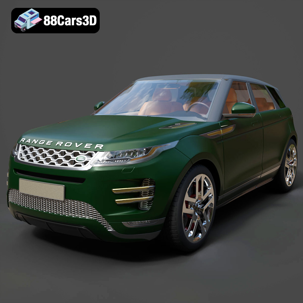
Texture: Yes | Material: Yes
Download the highly detailed, game-ready Range Rover Evoque R-Dynamic 2019 3D Model. Features flush deployable door handles, Matrix LED headlights, and R-Dynamic styling. Includes .blend, .fbx, .obj, .glb, .stl, .ply, .unreal, and .max formats for game development, AR/VR, and rendering.
Price: $19.99

Texture: Yes | Material: Yes
Download the highly detailed, game-ready Ford Mustang Mach 40 3D Model. Features aggressive custom widebody styling, a mid-mounted V8 engine, and classic retro-futuristic design. Includes .blend, .fbx, .obj, .glb, .stl, .ply, .unreal, and .max formats for game development, AR/VR, and rendering.
Price: $19.99
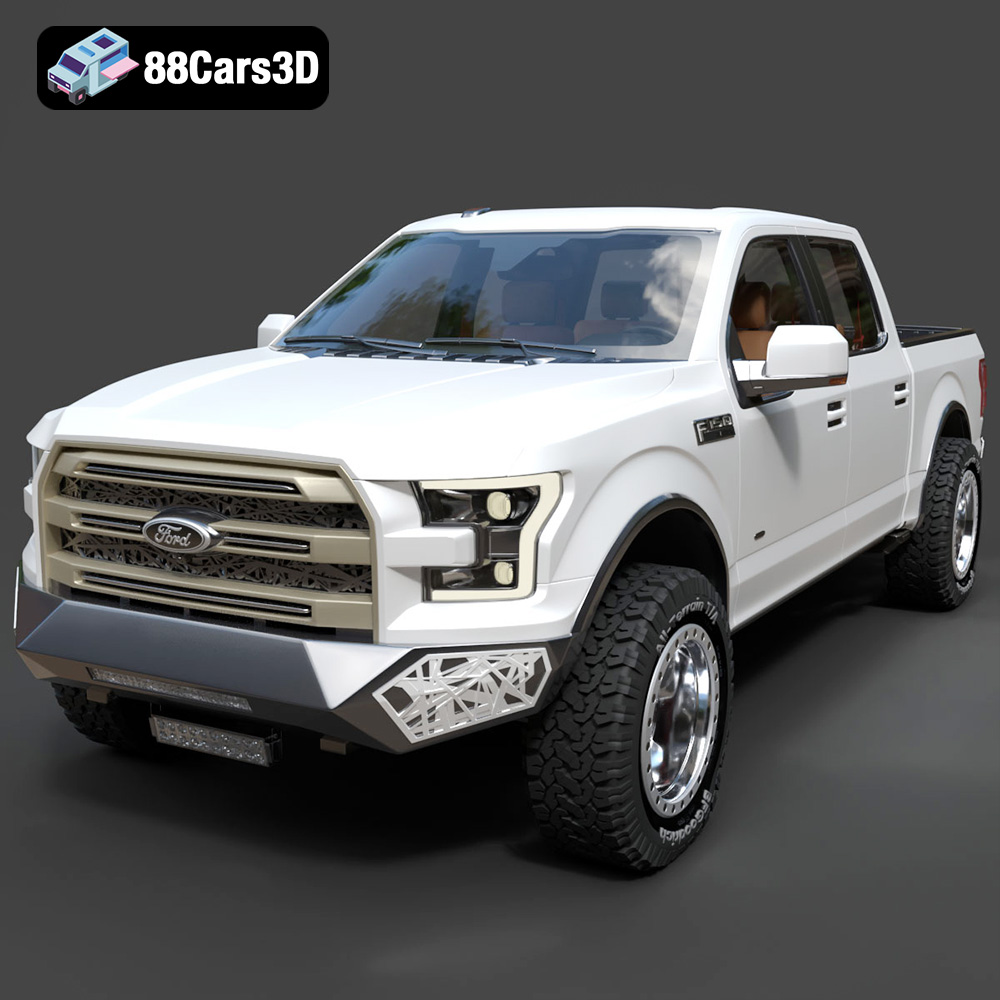
Texture: Yes | Material: Yes
Download the highly detailed, game-ready Ford F150 Raptor With Tuning From ARE 3D Model. Features custom ARE tuning accessories, aggressive off-road suspension, and rugged beadlock wheels. Includes .blend, .fbx, .obj, .glb, .stl, .ply, .unreal, and .max formats for game development, AR/VR, and rendering.
Price: $19.99

Texture: Yes | Material: Yes
Download the highly detailed, game-ready Mercedes-Benz AMG GLE 63 2021 3D Model. Features the iconic Panamericana grille, aggressive aerodynamic body styling, and a meticulously detailed luxurious interior. Includes .blend, .fbx, .obj, .glb, .stl, .ply, .unreal, and .max formats for game development, AR/VR, and rendering.
Price: $19.99
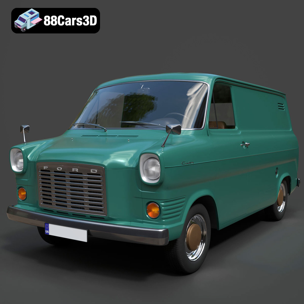
Texture: Yes | Material: Yes
Download the highly detailed, game-ready Ford Transit Mk1 Panel Van 1965 3D Model. Features iconic flat-front styling, vintage steel wheels, and a period-correct cargo bay. Includes .blend, .fbx, .obj, .glb, .stl, .ply, .unreal, and .max formats for game development, AR/VR, and rendering.
Price: $19.99

Texture: Yes | Material: Yes
Download the highly detailed, game-ready BMW X3 2024 3D Model. Features the iconic kidney grille, dynamic SUV proportions, and precise lighting elements. Includes .blend, .fbx, .obj, .glb, .stl, .ply, .unreal, and .max formats for game development, AR/VR, and rendering.
Price: $19.99

Texture: Yes | Material: Yes
Download the highly detailed, game-ready Tesla Model S Plaid 2021 3D Model. Features sleek aerodynamic styling, signature LED lighting, and the revolutionary Yoke steering interior. Includes .blend, .fbx, .obj, .glb, .stl, .ply, .unreal, and .max formats for game development, AR/VR, and rendering.
Price: $19.99

Texture: Yes | Material: Yes
Download the highly detailed, game-ready Rolls-Royce Ghost EWB 2018 3D Model. Features the iconic Pantheon grille, elongated luxury chassis, and elegant exterior lines. Includes .blend, .fbx, .obj, .glb, .stl, .ply, .unreal, and .max formats for game development, AR/VR, and rendering.
Price: $19.99
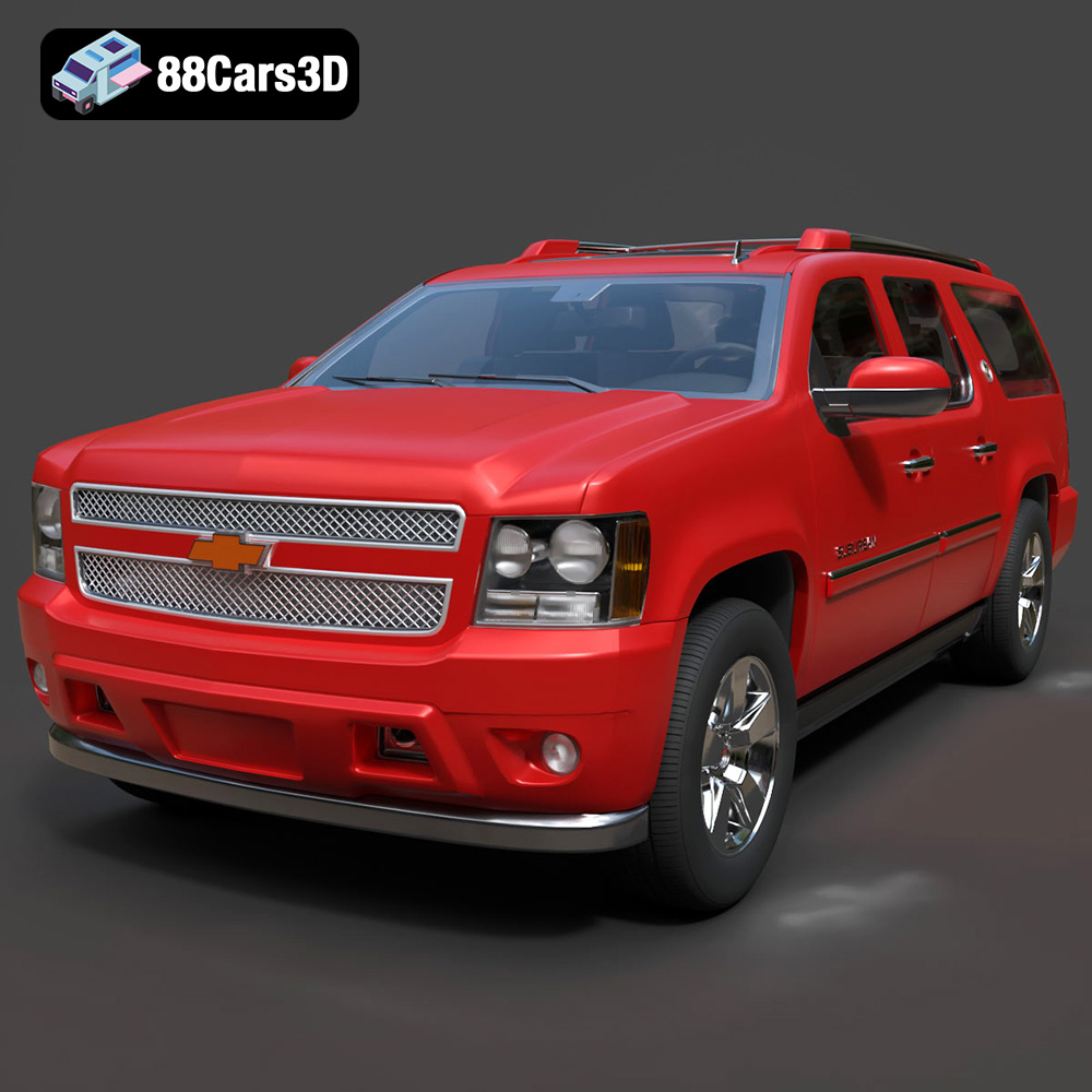
Texture: Yes | Material: Yes
Download the highly detailed, game-ready Chevrolet Suburban 75th Diamond 3D Model. Features the iconic Diamond Edition styling, detailed interior, and accurate full-size SUV proportions. Includes .blend, .fbx, .obj, .glb, .stl, .ply, .unreal, and .max formats for game development, AR/VR, and rendering.
Price: $19.99

