
In the demanding world of 3D automotive design, game development, and high-fidelity visualization, the underlying structure of a 3D model is just as crucial as its outward appearance. While initial modeling might prioritize form and artistic expression, the subsequent process of **retopology** transforms a dense, often irregular mesh into a clean, efficient, and production-ready asset. For anyone aiming to create truly professional 3D car models – whether for cinematic renders, immersive AR/VR experiences, game engines, or even 3D printing – mastering retopology in Blender is an indispensable skill.
This comprehensive guide will delve deep into the technical workflows and best practices for retopologizing 3D car models using Blender. We’ll explore why clean topology is paramount for performance, animation, and realistic shading, and how it directly impacts the usability of your assets across various platforms. From understanding fundamental edge flow principles specific to automotive surfaces to leveraging Blender’s powerful toolset, and ultimately optimizing your meshes for diverse applications, we’ll equip you with the knowledge to elevate your 3D car models to industry-leading standards. Get ready to transform your raw sculpts and high-polygon CAD imports into optimized masterpieces, ready for any production pipeline.
Topology refers to the arrangement of vertices, edges, and faces that form the surface of your 3D model. In automotive design, where sleek curves, sharp creases, and precise panel gaps define the aesthetic, impeccable topology is not merely a nicety – it’s a fundamental requirement. A well-constructed mesh ensures that your 3D car model will deform predictably, shade smoothly, and perform efficiently across all applications. Poor topology, conversely, can lead to rendering artifacts, animation glitches, and unwieldy file sizes, severely limiting the model’s utility. The goal of retopology is to create a clean, quad-based mesh that faithfully represents the high-detail original while optimizing for efficiency and functionality.
For 3D car models, specifically, the challenges are unique. Surfaces are often large and continuous, demanding consistent quad density to maintain smoothness. Hard edges and panel lines require deliberate edge loops to define their sharpness without adding unnecessary geometry to flatter areas. Understanding these nuances is the first step toward successful retopology. This meticulous process directly impacts how light interacts with the surface, how textures are applied, and how the model behaves when animated or optimized for real-time engines. Ignoring topology can lead to frustrating issues down the line, costing valuable production time and compromising visual quality. Therefore, investing time in learning and executing proper retopology techniques is a non-negotiable step for any serious 3D artist specializing in vehicles.
The benefits of good topology extend far beyond a visually pleasing wireframe. For real-time applications like games or AR/VR, optimized polygon count is king. Every unnecessary polygon increases draw calls and rendering overhead, directly impacting frame rates and user experience. A retopologized model, precisely tailored for its intended use, can drastically reduce this overhead. For instance, a high-resolution concept sculpt of a car might have millions of polygons, making it unusable in a game engine. Retopology can reduce this to tens or hundreds of thousands of polygons while retaining visual fidelity through normal map baking.
Furthermore, animation, even subtle movements like door openings or suspension compression, relies on clean edge flow. When a mesh deforms, vertices move. If these vertices are part of irregular or stretched polygons (triangles, N-gons), the deformation will look jagged, unnatural, or “bumpy.” A quad-dominant mesh with strategically placed edge loops allows for smooth, predictable deformation. Good topology also simplifies UV mapping, ensuring textures wrap correctly and efficiently, without stretching or distortion. For automotive models, which often feature complex materials and intricate decals, pristine UVs are paramount. Clean geometry also makes future edits and adjustments much easier, a significant advantage in iterative design processes.
Automotive models demand specific considerations for edge flow. The primary goal is to maintain the visual integrity of the car’s sculpted forms while ensuring an efficient and predictable mesh. Key principles include:
1. Quad Dominance: Strive for an all-quad mesh. Triangles can be used sparingly in flat, non-deforming areas, but N-gons (faces with more than four vertices) should be avoided entirely, as they cause unpredictable shading and deformation.
2. Flow with Form: Edge loops should follow the natural curves and contours of the car. On a car fender, for instance, edge loops should flow along the length of the fender, wrapping around the wheel well, and defining the sharp crease lines.
3. Defining Hard Edges: Sharp creases, such as those found around windows, door seams, or body panels, require “holding” or “support” edge loops. These are additional edge loops placed very close to the primary edge, effectively creating a “chamfer” or bevel that allows the surface to appear sharp while still being smooth enough for subdivision surfaces.
4. Even Distribution: Maintain a relatively even distribution of polygons across large, smooth surfaces. Avoid excessively dense areas next to very sparse areas, as this can lead to shading inconsistencies.
5. Pole Management: Poles (vertices with more or less than four edges connected) are unavoidable but should be strategically placed. For automotive models, aim to place 5-pole vertices (star points) in areas of low curvature or where multiple edge flows converge, and avoid 3-pole vertices (T-junctions) on large, smooth surfaces, as they can cause pinching.
6. Panel Gaps: To create realistic panel gaps, you typically model the panels as separate objects or use dedicated edge loops to define their boundaries, allowing for a slight offset to simulate real-world construction. This approach provides greater control over shading and material assignments.
Adhering to these principles ensures that your 3D car model will not only look great but also perform optimally in any production environment, from a high-fidelity rendering pipeline to a demanding game engine.
Blender offers a robust set of tools and modifiers that make the retopology process manageable and efficient. While there are semi-automatic solutions available, a strong foundation in manual retopology techniques is essential for achieving the highest quality results, especially for intricate surfaces like those found on automotive models. The key is to leverage Blender’s snapping options, drawing tools, and mesh manipulation features to precisely lay down new geometry over your high-polygon source mesh. Familiarity with these tools, combined with a methodical approach, will significantly streamline your workflow. Many of these features can be found and explored in detail within the official Blender 4.4 documentation, which provides comprehensive guides on modeling tools and workflows at https://docs.blender.org/manual/en/4.4/.
The process generally involves projecting new, cleaner geometry onto the surface of a high-resolution reference mesh. This reference could be a detailed sculpt, a scanned model, or an imported CAD model. Blender’s interactive nature allows you to build your low-polygon mesh piece by piece, ensuring optimal edge flow and polygon distribution. Mastering these core tools is crucial for tackling the complexities of automotive surfaces, where precision and clean geometry are non-negotiable. It’s a process that requires patience and practice, but the payoff in model quality and versatility is immense.
Blender’s snapping system is the cornerstone of manual retopology. When enabled, it allows newly created or moved vertices, edges, and faces to “snap” precisely to the surface of another object – in this case, your high-poly reference car model.
Here’s how to set it up and use it effectively:
1. Enable Snapping: In the 3D Viewport header, click the magnet icon or press `Shift + Tab`.
2. Set Snap Element to “Face”: From the dropdown next to the magnet icon, choose “Face.” This ensures your geometry snaps to the surface of faces.
3. Enable “Project Individual Elements”: This option, also in the snapping dropdown, is crucial. It projects each vertex onto the surface, even if you’re moving a group of vertices or an entire face. Without this, only the “active” element might snap.
4. Activate “Snap to Self” (Optional but Recommended): In some versions, you might need to ensure this is enabled for elements to snap reliably.
5. Targeting the High-Poly Mesh: Select your high-poly car model and set it as your target for snapping. It’s often helpful to keep the high-poly mesh selectable but in wireframe or X-ray mode (`Alt+Z`) so you can see your new retopo mesh on top.
With snapping configured, you can then use various modeling tools:
* Extrude (`E`): Extrude edges or faces directly onto the high-poly surface.
* Draw Face Tool (Contour): A powerful add-on (often built-in, check your preferences under “Mesh: F2” for quick face creation) or manual face creation by selecting three or four vertices and pressing `F`.
* Knife Tool (`K`): Cut new edge loops or individual edges directly on the surface while snapping.
* Slide Vertices/Edges (`G G`): Move existing geometry along its edges while maintaining its position on the snapped surface. This is vital for refining edge flow without losing contact with the reference.
Always ensure your new retopology mesh is a separate object. You can also use the Shrinkwrap modifier (explained next) in conjunction with snapping for a more dynamic projection.
While manual snapping is precise, Blender offers modifiers that can assist and accelerate the retopology process, especially for maintaining surface adherence.
1. **Shrinkwrap Modifier:** This is a powerhouse for retopology. It projects one mesh onto the surface of another.
* Add a `Shrinkwrap` modifier to your low-poly retopology mesh.
* Set the `Target` to your high-poly car model.
* Choose a `Wrap Method`:
* **Nearest Surface Point:** Good for general projection.
* **Project:** Allows you to specify an axis to project along (e.g., negative Z) which can be useful for cleaner results but might miss details if the high-poly surface is complex.
* The `Offset` value allows you to keep a tiny distance between your retopo mesh and the high-poly, preventing Z-fighting.
* **Workflow:** You can model with snapping enabled, and the Shrinkwrap modifier will continuously project your retopo mesh onto the target. This ensures your mesh always stays on the surface, freeing you from constantly checking for gaps. You can toggle the modifier on/off in Edit Mode to see your original geometry. Once satisfied, apply the modifier.
2. **Mirror Modifier:** Essential for symmetrical objects like cars.
* Add a `Mirror` modifier to your retopology mesh.
* Ensure the origin point of your retopo mesh is at the center of your high-poly car model (usually the world origin).
* Enable `Clipping` to prevent vertices from crossing the mirror plane.
* This allows you to model only one half of the car, with the other half automatically mirrored, saving immense time and ensuring perfect symmetry.
3. **Subdivision Surface Modifier:** While not directly a retopology tool, it’s crucial for verifying your retopology.
* Apply a `Subdivision Surface` modifier (often referred to as ‘Subsurf’) to your completed low-poly mesh.
* This will smooth out the mesh, and if your topology is clean, it should flawlessly replicate the smooth curves of the high-poly original. Any pinching, bumps, or irregular shading indicates areas where your edge flow needs refinement. Use it as a visual feedback mechanism throughout the process.
By combining manual snapping, the Shrinkwrap modifier for constant surface projection, and the Mirror modifier for symmetry, Blender provides a highly efficient and accurate environment for retopologizing even the most complex 3D car models.
Beyond the fundamental tools, tackling the intricate surfaces and precise details of automotive models requires advanced strategies. Car bodies are a masterclass in controlled curvature, sharp creases, and perfectly aligned panel gaps. These features demand specific retopology approaches to ensure they are captured accurately and efficiently in the low-polygon mesh, ultimately preparing the model for high-quality rendering, real-time engines, or even precise manufacturing processes like 3D printing. The techniques discussed here focus on maintaining detail where it matters most, managing polygon density, and ensuring the final mesh is as clean and versatile as possible. Mastering these methods will differentiate your 3D car models, ensuring they meet the stringent demands of professional production pipelines.
Automotive design is characterized by crisp lines and defined features. Capturing these effectively in a retopologized mesh is critical.
* **Holding Edge Loops:** For sharp edges (e.g., the edge of a headlight, a character line on the hood), you need “holding” or “support” edge loops. These are typically two or three edge loops placed very close to the primary edge that defines the sharpness. When a Subdivision Surface modifier is applied, these tight loops prevent the area from rounding off excessively, preserving the crispness. The tighter the loops, the sharper the edge. You should strategically place these only where necessary to control polygon count.
* **Creases:** Blender’s `Crease` function (`Shift + E` in Edit Mode) allows you to add sharpness to edges or vertices without adding geometry. This can be useful during the early stages of retopology or for details that don’t need permanent support loops. However, for production-ready models, especially those going into game engines or needing specific baking, explicit holding loops are generally preferred as they offer more predictable results and aren’t tied to Blender’s internal crease data.
* **Panel Gaps:** Real cars have distinct gaps between panels (doors, hood, trunk). In 3D, these can be achieved in a few ways:
* **Separate Meshes:** The most robust method is to model each major panel (hood, door, fender) as a separate, retopologized mesh. This naturally creates a “gap” between them and allows for realistic material separation, animation, and damage modeling. Ensure the edges facing the gap have their own holding loops to maintain sharpness.
* **Edge Loops and Bevels:** For models requiring a single continuous mesh (less common for hyper-realistic cars but useful for some game assets), you can define panel lines with tight edge loops. Then, use Blender’s `Bevel` tool (`Ctrl + B`) on these edge loops to create a small “gap” geometry. This creates a recess that mimics a panel line. This method can increase polygon count but maintains a unified mesh.
* **Normal Map Baking:** Often, the subtle depth of a panel gap is baked from a high-poly sculpt onto the low-poly mesh’s normal map. This creates the illusion of depth without adding significant geometry. This is commonly combined with separate meshes or simple edge loops to define the general area.
Efficiency is key in retopology, and automotive models, being largely symmetrical, benefit immensely from mirroring techniques.
* **Mirror Modifier:** As mentioned, Blender’s `Mirror` modifier (`Ctrl + M` then `X`, `Y`, or `Z` after setting the origin) is indispensable. Always work on one side of the car and let the modifier duplicate the work. Ensure your object’s origin is exactly on the plane of symmetry (usually the world origin) and that `Clipping` is enabled to prevent vertices from crossing the center line.
* **Symmetrizing Existing Meshes:** If you start with a mesh that isn’t perfectly symmetrical (e.g., a scan or a freehand sculpt), Blender’s `Symmetrize` tool can help. In `Edit Mode`, select all vertices, then go to `Mesh > Symmetrize`. You can choose the axis and direction (e.g., +X to -X). This will attempt to make one side of the mesh perfectly mirror the other. Be cautious, as this can sometimes distort details if the asymmetry is significant. For retopology, it’s often better to retopologize one side perfectly and then mirror, rather than trying to fix a highly asymmetrical high-poly.
* **Projecting Details:** After retopologizing the main form of the car, you might have smaller details (vents, badges, intricate grilles) that are difficult or inefficient to retopologize directly onto the main mesh.
* **Separate Mesh Approach:** Model these details as separate, optimized meshes. For example, a car grille might be a separate low-poly object rather than part of the main body panel. This allows for individual UV mapping and material assignment, and you can bake details from a high-poly version of that specific component.
* **Normal Map Baking:** For very fine surface details that don’t require actual geometry (e.g., subtle textures, small engravings, or very shallow recesses), use normal map baking. This projects the fine surface variations from your high-poly original onto the low-poly normal map, giving the illusion of detail without extra polygons. This is a cornerstone of game asset development and high-efficiency rendering.
* **Decals:** For logos, text, or minor surface details, applying them as texture decals onto your UV-mapped surface can be extremely efficient, bypassing the need for geometric representation altogether.
By thoughtfully applying these advanced techniques, you can ensure that your retopologized 3D car models are not only visually accurate but also structurally sound, optimized, and ready for any professional application.
Once you’ve crafted a perfectly clean, quad-based retopology for your 3D car model in Blender, the next critical step is to tailor and optimize it for its specific end-use. A model destined for a hyper-realistic cinematic render will have different polygon and texture requirements than one designed for a mobile AR application or a real-time game. This optimization phase involves making informed decisions about polygon count, level of detail (LODs), material setups, and overall asset efficiency. The beauty of a well-retopologized base mesh is its adaptability; it can be quickly iterated upon to create multiple versions suitable for various platforms without compromising the core design integrity.
This section will guide you through preparing your automotive assets for the most common professional scenarios, ensuring that your meticulously retopologized models deliver peak performance and visual fidelity, whether on a powerful rendering workstation or a constrained mobile device. Understanding these optimization strategies is crucial for any artist looking to deliver truly versatile 3D car models.
Game engines like Unity and Unreal Engine demand highly optimized assets to maintain high frame rates. Your retopologized car model, while cleaner, still needs further consideration.
* **Level of Detail (LODs):** This is paramount for game assets. An LOD system swaps out higher-polygon meshes for lower-polygon versions as the camera moves further away from the object.
* **Creation:** Start with your primary retopologized mesh (LOD0). Then, create successive lower-polygon versions (LOD1, LOD2, etc.) by progressively dissolving edge loops or simplifying geometry in Blender. For a car, typical LODs might be:
* **LOD0 (High):** ~80,000-200,000 tris (for close-up shots, interior details).
* **LOD1 (Medium):** ~20,000-50,000 tris (for normal gameplay distance).
* **LOD2 (Low):** ~5,000-15,000 tris (for distant views, simpler shapes).
* **LOD3 (Very Low):** ~500-2,000 tris (for extreme distance, often just a basic silhouette).
* **Process:** After creating lower LODs, you often need to re-bake normal maps from the original LOD0 or even the ultra-high-poly source onto these simpler meshes to retain surface detail.
* **Draw Calls:** Every distinct material, mesh, and light source contributes to draw calls, which can bottleneck performance.
* **Material Reduction:** Try to combine materials where possible. A car might have separate materials for paint, glass, tires, chrome, but consolidating smaller interior pieces or undercarriage elements into fewer materials can help.
* **Texture Atlasing:** Combining multiple smaller textures into one large texture atlas reduces material calls. For instance, all small interior buttons and dashboard elements could share one texture atlas, which is then mapped across different parts of the mesh’s UVs.
* **Batching:** Game engines can “batch” similar objects (sharing the same material) to reduce draw calls. Your clean retopology and organized materials facilitate this.
* **Occlusion Culling:** Ensure your mesh is “watertight” and free of internal geometry that won’t be seen. This allows game engines to effectively use occlusion culling, which prevents rendering objects or parts of objects that are hidden behind others.
While game engines prioritize performance, high-fidelity rendering (e.g., in Corona, V-Ray, Cycles, Arnold) focuses on visual realism. AR/VR applications strike a balance, demanding both visual quality and real-time performance.
* **High-Fidelity Rendering:**
* **Subdivision Surfaces:** Your retopologized mesh, when combined with a `Subdivision Surface` modifier in Blender (applied at render time or exported with subdivisions), will produce perfectly smooth, high-detail surfaces ideal for close-up renders. The clean quad topology ensures smooth shading and predictable light interaction.
* **PBR Materials:** Prepare your material slots with appropriate PBR (Physically Based Rendering) texture maps (Albedo/Base Color, Metallic, Roughness, Normal, Ambient Occlusion). Ensure your UVs are clean and unwrapped efficiently for optimal texture resolution.
* **Optimized Scene:** While the car model is optimized, ensure the rendering environment (lighting, background) is also efficient. Use instancing for repetitive elements (e.g., tire treads, small bolts) to save memory.
* **AR/VR Optimization:**
* **Moderate Polygon Count:** AR/VR models need to be low-to-mid poly, often similar to LOD1 or LOD2 for games (e.g., 20,000-80,000 triangles for a full car model, depending on the platform).
* **Texture Resolution:** Use judiciously chosen texture resolutions. 2K or 4K maps for major body panels are often sufficient, while smaller components can use 1K or 512px.
* **Draw Calls:** Similar to game engines, minimize materials and use texture atlasing.
* **Single-Pass Materials:** If possible, use materials that support single-pass rendering to reduce rendering overhead.
* **Simplified Shaders:** Avoid complex shader networks that might be too heavy for mobile AR/VR devices.
* **Real-world Scale:** Ensure your 3D car model is built to real-world scale in Blender. This is crucial for accurate placement and interaction in AR/VR environments.
3D printing requires solid, “watertight” meshes without any gaps, non-manifold geometry, or intersecting faces. Your retopologized mesh provides an excellent foundation.
* **Manifold Geometry:** A 3D printable model must be “manifold,” meaning every edge belongs to exactly two faces. Non-manifold geometry (e.g., an edge belonging to one or three faces, loose vertices/edges, internal faces) will cause errors during slicing.
* **Watertight Mesh:** Ensure your retopologized car model is a completely closed volume. There should be no holes or open edges.
* **Mesh Repair in Blender:**
* **Check All (`Ctrl + Shift + Alt + M`):** In Edit Mode, use `Select > Select All by Trait > Non Manifold` to identify problem areas.
* **Merge by Distance:** Select all vertices (`A`) and then `Mesh > Clean Up > Merge by Distance` to remove duplicate vertices.
* **Make Manifold:** Blender’s 3D Print Toolbox add-on (enable it in `Edit > Preferences > Add-ons`) has a “Make Manifold” button that attempts to fix non-manifold geometry.
* **Solidify Modifier:** For extremely thin surfaces that might cause printing issues, a `Solidify` modifier can add thickness.
* **Triangulation:** Most 3D printers prefer triangulated meshes. While Blender’s internal operations work with quads, before exporting for 3D printing, it’s often wise to triangulate the mesh (`Ctrl + T` in Edit Mode with all faces selected) to ensure consistent slicing, though many slicers handle quads fine.
* **Scale and Orientation:** Ensure your model is at the correct physical scale and oriented correctly for printing (e.g., flat on the build plate to minimize supports).
By strategically optimizing your retopologized 3D car models for these diverse applications, you ensure that your assets are not only visually stunning but also highly functional and performant across the entire spectrum of 3D production. Platforms like 88cars3d.com thrive on providing models that meet these rigorous standards, offering artists and developers a reliable source for production-ready content.
A perfectly retopologized 3D car model is a beautiful thing, but its true potential is unlocked only when combined with efficient UV mapping and high-quality texture baking. These two processes are intrinsically linked to the underlying mesh topology: clean, organized quads make UV unwrapping a predictable and enjoyable task, while baking textures from a high-resolution source onto a low-polygon, UV-mapped mesh is the cornerstone of realistic visual fidelity in both real-time and offline rendering contexts. Without proper UVs and baked textures, even the most meticulously retopologized model will appear flat and unconvincing.
This section will guide you through the essential steps of preparing your automotive meshes for texturing, focusing on strategies that maximize texture utilization and minimize distortion. We’ll explore how to create logical UV layouts for complex car surfaces and delve into the critical process of baking various texture maps in Blender, ensuring your car models are ready for advanced PBR material creation and stunning visual output.
UV mapping is the process of flattening a 3D mesh into a 2D plane so that a 2D image (texture) can be applied to it. For automotive models, which feature large, continuous surfaces and intricate details, an efficient and logical UV layout is paramount.
* **Seam Placement:** The art of UV mapping lies in strategic seam placement.
* **Follow Natural Edges:** Place seams along natural breaks or hard edges of the car model, such as where panels meet, along the undersides of bumpers, or hidden areas like the inside of fender wells. This minimizes visible texture seams.
* **Minimize Cuts:** While seams are necessary, try to minimize the number of cuts to create fewer UV islands, which can lead to more efficient packing and fewer texture distortions.
* **Straight Edges:** Whenever possible, make your UV islands have straight edges. This makes tiling textures easier and reduces pixelation along borders.
* **Unwrapping Techniques in Blender:**
* **Mark Seams:** In Edit Mode, select edges and press `Ctrl + E > Mark Seam`.
* **Unwrap:** With seams marked and faces selected, press `U > Unwrap`. Blender offers several unwrapping methods:
* **Smart UV Project:** Good for quick initial unwraps or complex mechanical parts, but often creates many small islands and can be inefficient for large surfaces.
* **Lightmap Pack:** Useful for lightmap baking, less ideal for diffuse textures.
* **Follow Active Quads:** Excellent for unwrapping long, rectangular strips of quads (e.g., side panels) into straight, uniform UVs.
* **Cylinder/Sphere Projection:** Useful for parts like wheels or spherical elements.
* **Packing UV Islands:** After unwrapping, your UV islands need to be arranged within the 0-1 UV space of the texture map.
* **UV Sync Selection:** In the UV Editor, ensure “UV Sync Selection” is off (the two overlapping square icon). This allows you to select and move UV islands independently.
* **Scale and Rotate:** Manually scale and rotate islands to maximize the use of the UV space, giving more texture resolution to prominent parts of the car (e.g., body panels, hood) and less to hidden or less important areas (e.g., undercarriage).
* **Average Island Scale:** Use `UV > Average Island Scale` to normalize the texture density across different islands, preventing some parts from having blurry textures while others are sharp.
* **Pack Islands:** Use `UV > Pack Islands` (or the corresponding function in the UV Editor’s `UV` menu) to automatically arrange and scale your UV islands to fit within the 0-1 space. Adjust padding to prevent texture bleeding between islands.
* **UDIM Workflows:** For extremely high-detail automotive models (e.g., for VFX or cinematic renders) that require very high texture resolution without sacrificing packing efficiency, consider using UDIMs. This system allows you to use multiple UV tiles (separate 0-1 UV spaces) per mesh, effectively allowing you to have dozens of 4K or 8K textures without splitting the mesh. While more advanced, Blender supports UDIM workflows for both painting and rendering.
Texture baking is the process of transferring surface details, lighting information, or material properties from one mesh (usually a high-poly sculpt) to another (your low-poly, UV-mapped retopology mesh). This is a crucial step for bringing life and realism to your retopologized car model.
1. **Preparation:**
* **High-Poly Source:** Ensure your high-poly car model is in a separate Blender scene or collection, with its scale and position perfectly matching your low-poly retopology mesh.
* **Low-Poly Target:** Your low-poly retopology mesh must have clean UVs.
* **Material:** Add a material to your low-poly mesh (any material will do, as we’ll be baking to an image texture node within it).
* **Image Texture Node:** In the Shader Editor, add an `Image Texture` node to your low-poly material. Click `New` to create a blank image (e.g., 4096×4096, 32-bit float for Normals, or 8-bit for AO/Curvature). Leave it unconnected for now; this is where Blender will bake the data.
2. **Baking in Blender (Cycles Render Engine):**
* Switch to the `Cycles` render engine (Blender Internal is deprecated, Eevee doesn’t have the same comprehensive baking options).
* Go to the `Render Properties` tab. Scroll down to `Bake`.
* **Bake Type:**
* **Normal:** Bakes surface detail from the high-poly to a normal map. Select `Normal`. Set `Space` to `Tangent` (most common for game engines and PBR workflows).
* **Ambient Occlusion (AO):** Bakes shadow information from crevices and contact points. Select `AO`.
* **Curvature (via custom setup):** Blender doesn’t have a direct “Curvature” bake type. Instead, you’ll need a custom shader node setup on your *high-poly* mesh that outputs curvature (e.g., using the `Pointiness` attribute of the `Geometry` node and a `ColorRamp`) and then bake it as an `Emit` pass.
* **Selected to Active:** Crucially, check `Selected to Active`. This tells Blender to bake from the currently *selected* object(s) (your high-poly) to the *active* object (your low-poly).
* **Extrusion/Cage:**
* **Extrusion:** A value (e.g., 0.05m-0.1m) that expands the high-poly mesh’s projection distance to prevent missing details.
* **Cage:** For more precise baking, especially with complex shapes, create a “cage” mesh. Duplicate your low-poly, scale it slightly outward, and select it *after* the high-poly and *before* the low-poly. Specify the cage object in the `Bake` panel.
* **Bake:** With your high-poly selected (and cage if used), then your low-poly selected (and active), and the blank image node active in your low-poly material, click `Bake`.
3. **Post-Baking:**
* Save your baked image textures immediately (`Image Editor > Image > Save As`).
* Connect your baked maps to your PBR shader network (e.g., `Normal Map` node for normals, `Principled BSDF` for AO, etc.).
This process of baking normal, ambient occlusion, and other utility maps allows you to represent an incredible amount of surface detail on a relatively low-polygon mesh, making your retopologized 3D car models both visually rich and highly performant.
Even with the right tools and a solid understanding of principles, retopology can present significant hurdles, especially when dealing with complex source geometry like that of automotive models. High-resolution scans, intricate CAD imports, or dense sculpts often come with their own set of inherent issues: messy triangulation, non-manifold geometry, inconsistent surface detail, or extreme polygon counts. Navigating these challenges effectively requires a combination of diagnostic skills, strategic planning, and specific Blender techniques to clean up and prepare the source data before or during the retopology process.
This section will address some of the most common difficulties encountered in retopologizing 3D car models and provide professional-grade solutions. Learning how to identify and rectify these problems early on will not only save you considerable time and frustration but also ensure the integrity and quality of your final retopologized mesh, allowing you to produce truly production-ready assets for any demanding project.
Working with incredibly dense meshes from 3D scans or CAD software (Computer-Aided Design) is a common starting point for automotive retopology, but these sources often come with unique problems.
* **Excessive Polygon Count:** Scans can have millions of triangles, making them unwieldy to work with directly. CAD data, when tessellated, can also generate extremely dense and often messy meshes.
* **Solution: Decimation:** Before starting retopology, consider decimating the high-poly mesh in Blender using the `Decimate` modifier. Apply it and set the `Ratio` to a lower value (e.g., 0.1-0.2) or use `Planar` or `Un-Subdivide` modes. The goal isn’t to make it low-poly enough for the final product, but to make it *manageable* for snapping and visual reference, reducing lag in the viewport. Be careful not to lose critical details.
* **Isolate Sections:** If the car model is extremely large and complex, consider retopologizing it in logical sections (e.g., one fender, then the door, then the hood). You can then merge these pieces later.
* **Triangulated and Messy Topology:** Scans and CAD conversions are almost always triangulated, and their edge flow often doesn’t follow the aesthetic lines of the car.
* **Solution: Ignore Source Topology:** The key is to *not* try to follow the high-poly’s topology. Your retopology mesh will be entirely new, built from scratch with clean quads and optimal edge flow. The high-poly simply serves as a surface guide for snapping.
* **Non-Manifold Geometry & Holes:** Scans, especially, can have holes, internal geometry, and non-manifold edges, making them difficult as reference meshes.
* **Solution: Clean Up Source:** Before retopology, try to clean the high-poly mesh. In Blender, select the mesh, go to `Edit Mode`, select all (`A`), then `Mesh > Clean Up > Fill Holes`, `Delete Loose`, and `Merge by Distance`. For larger holes, you might need to manually select edge loops and use `F` to create faces or `Grid Fill`. Use the `3D Print Toolbox` add-on to check for non-manifold errors. While a perfectly clean high-poly isn’t strictly necessary for snapping, fixing major issues will prevent visual glitches during baking.
* **Scaling Issues:** Imported CAD files can sometimes come in at incorrect scales.
* **Solution: Apply Scale:** Ensure both your high-poly source and your new retopology mesh have their scale applied (`Ctrl + A > Scale`) in Object Mode, and that they are set to real-world dimensions for consistency.
Even with careful retopology, issues can arise in the final low-poly mesh or during the baking process.
* **Pinching and Shading Artifacts:** These appear as unnatural sharp points or wavy patterns on smooth surfaces, often caused by poor pole placement or inconsistent quad density.
* **Solution: Refine Edge Flow:** Analyze the affected area. Are there 3-poles (T-junctions) on a smooth surface? Are quads stretched or unevenly distributed? Use `Slide Edge` (`G G`) to even out geometry. Merge vertices (`Alt + M`) or dissolve edges (`X > Dissolve Edges`) to simplify redundant loops. Re-route edge flow to guide poles into flatter, less visible areas. Apply a `Subdivision Surface` modifier to diagnose; good topology will subdivide cleanly.
* **Texture Bleeding/Seams:** Visible lines where UV islands meet after baking.
* **Solution: UV Padding and Extrusion:** When baking, ensure you have sufficient `Extrusion` (or `Max Ray Distance` depending on the baker) and `Padding` set in your baking software. Padding adds extra pixels around UV islands to prevent bleeding. For Blender’s internal baker, ensure your image texture has enough `Margin` (Image Editor > Image > New > Generate Type: Blank, then adjust Margin).
* **Seam Placement:** Re-evaluate your UV seam placement. Are they in inconspicuous areas? Are they sharp edges on the model?
* **Normal Map Artifacts (Hard Edges, Stair-stepping):** Jagged lines or visible “steps” on surfaces that should be smooth, especially around hard edges.
* **Solution: Smooth Shading and Autosmooth:** Ensure your low-poly model is set to `Smooth Shading` (`Object > Shade Smooth`). Use `Object Data Properties > Normals > Auto Smooth` with an angle (e.g., 30-60 degrees) to control where hard edges appear.
* **Weighted Normals:** For extremely sharp edges, consider using a `Weighted Normal` modifier, which helps prevent faceted normal map appearance on flat surfaces next to beveled edges.
* **Tangent Space:** When baking normal maps, ensure both the high-poly and low-poly meshes use consistent tangent spaces if your external baking tool allows it (Blender’s default `Tangent` space for normal maps is usually reliable).
* **Intersecting Geometry:** Parts of the mesh overlapping or poking through others, often after modifiers or manual edits.
* **Solution: Non-Manifold Check:** Use `Select > Select All by Trait > Non Manifold` to find these issues.
* **Boolean/Voxel Remesh (for source):** For severely intersecting high-poly source meshes, a `Boolean` union or `Voxel Remesh` (in Sculpt Mode) can sometimes “solidify” the mesh, but this is destructive and generates new dense topology that would need retopology. Use cautiously on source.
* **Manual Adjustment:** For the low-poly, simply move vertices or faces to prevent intersections. Ensure the `Shrinkwrap` modifier is set up correctly with an `Offset` to prevent collision with the high-poly.
By methodically addressing these common challenges and implementing these professional solutions, you can significantly improve the quality and efficiency of your retopology workflow in Blender, ultimately leading to superior 3D car models.
The journey from a raw, high-polygon sculpt or CAD import to a perfectly optimized, production-ready 3D car model is a testament to precision, patience, and technical expertise. As we’ve thoroughly explored, mastering retopology in Blender is not just about creating visually clean wireframes; it’s about laying down the fundamental blueprint that dictates your model’s performance, animation capabilities, shading accuracy, and overall adaptability across a myriad of applications, from cinematic renders to immersive AR/VR experiences and demanding game engines.
We’ve delved into the specific demands of automotive topology, emphasizing how intelligent edge flow, strategic pole placement, and meticulous panel gap definition ensure your vehicle assets stand up to the closest scrutiny. Blender’s powerful toolkit, from precise snapping and the versatile Shrinkwrap modifier to advanced techniques for managing hard edges and leveraging symmetry, provides artists with all the necessary instruments. Furthermore, we’ve outlined how to rigorously optimize your retopologized meshes with LODs for real-time performance, prepare them for high-fidelity PBR rendering, and even make them watertight for 3D printing. The crucial steps of efficient UV mapping and accurate texture baking then breathe life into these optimized structures, showcasing the intricate details captured from your high-poly sources.
Remember, the quality of your retopology directly influences every subsequent stage of your 3D pipeline. Investing the time to cultivate these skills will not only elevate the visual fidelity and technical robustness of your 3D car models but also significantly streamline your workflow, making you a more efficient and sought-after artist in the competitive fields of automotive design, visualization, and game development. For artists and studios seeking high-quality, pre-optimized 3D car models, platforms like 88cars3d.com offer assets that are already built with these exacting standards in mind, providing a head start on any project. Embrace the art and science of retopology, and watch your 3D car models drive into a new era of excellence.
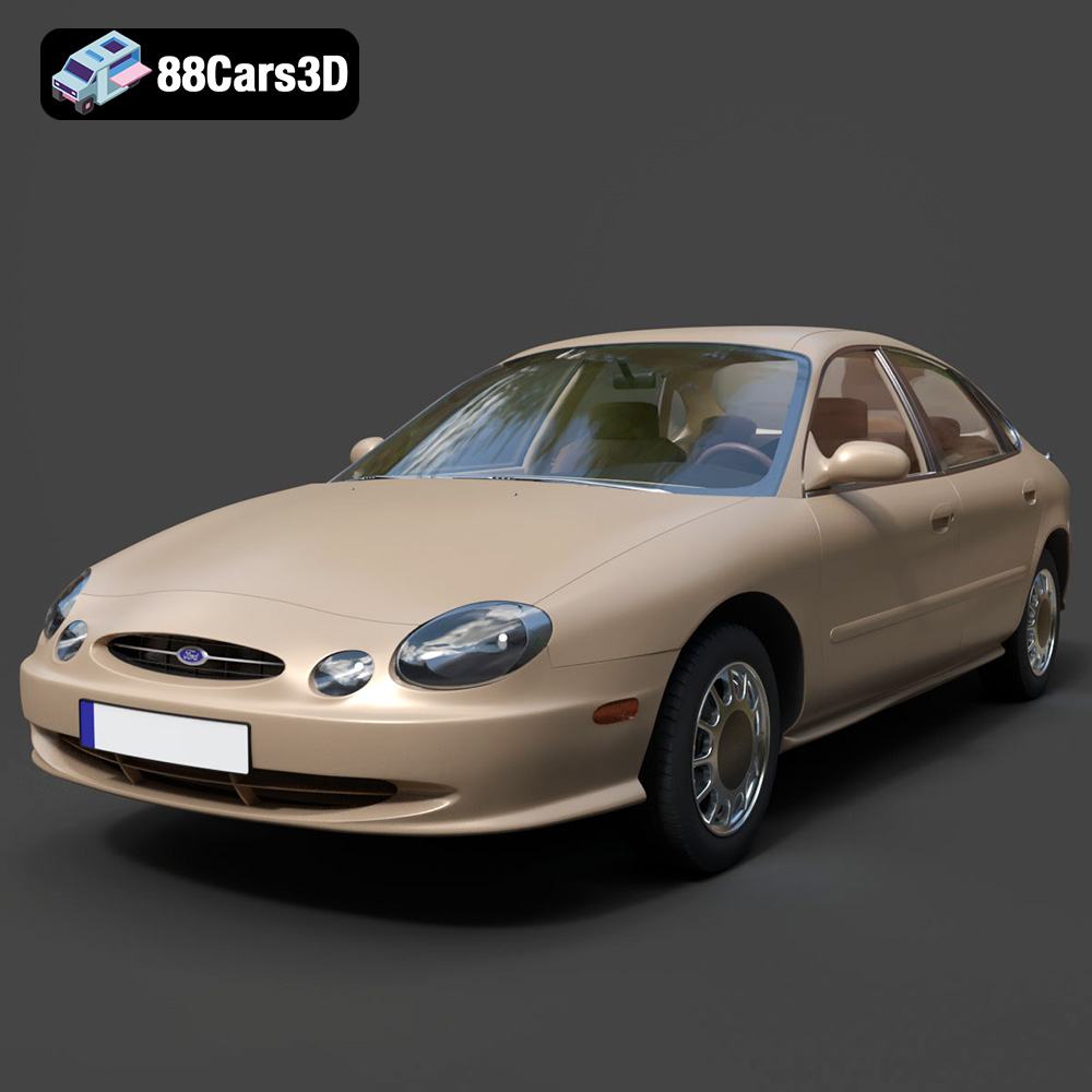
Texture: Yes | Material: Yes
Download the highly detailed, game-ready Ford Taurus 1996 3D Model. Features revolutionary oval exterior styling, detailed interior, and accurate chassis geometry. Includes .blend, .fbx, .obj, .glb, .stl, .ply, .unreal, and .max formats for game development, AR/VR, and rendering.
Price: $161.00
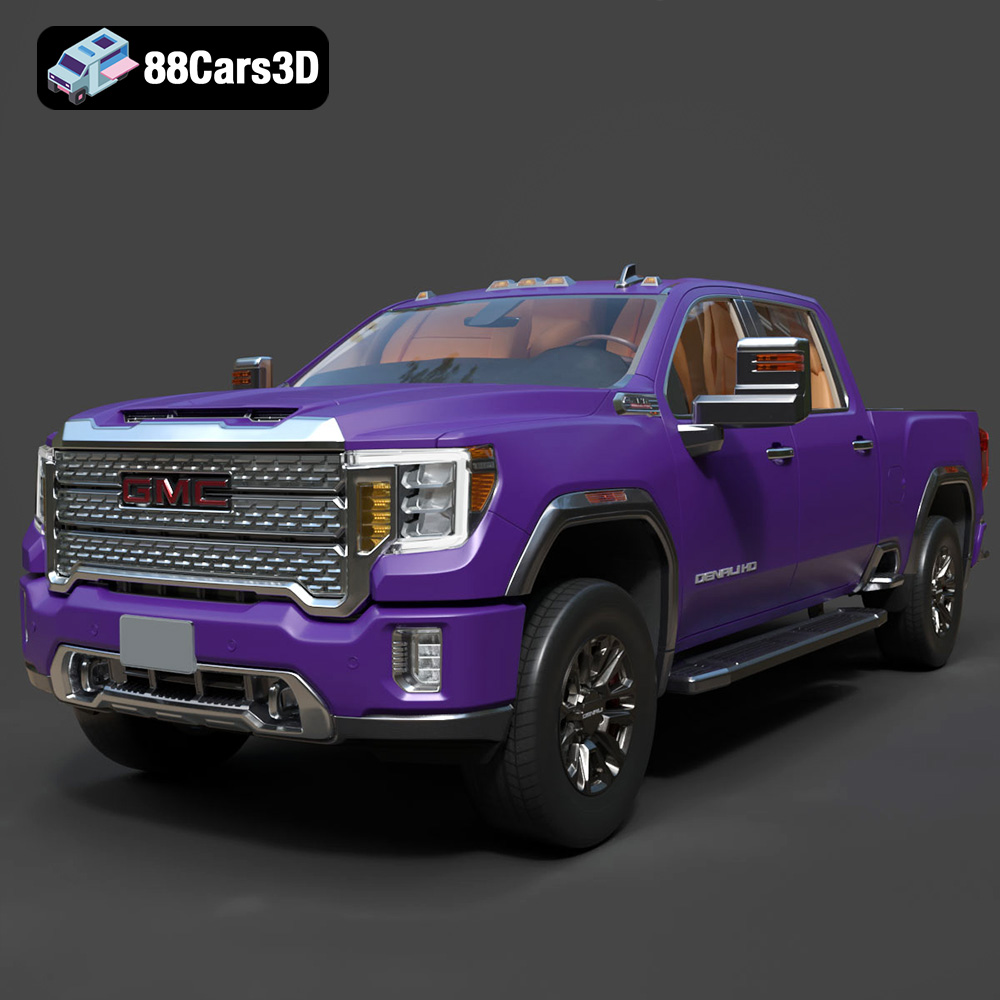
Texture: Yes | Material: Yes
Download the highly detailed, game-ready GMC Sierra HD Denali 2020 3D Model. Features iconic chrome Denali grille, detailed MultiPro tailgate, and heavy-duty chassis styling. Includes .blend, .fbx, .obj, .glb, .stl, .ply, .unreal, and .max formats for game development, AR/VR, and rendering.
Price: $274.50
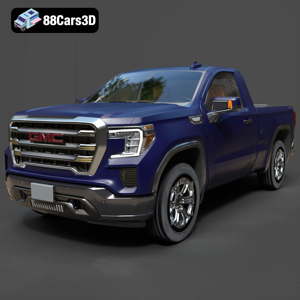
Texture: Yes | Material: Yes
Download the highly detailed, game-ready GMC Sierra Reg SLE 1500 2020 3D Model. Features bold pickup styling, detailed exterior trim, accurate undercarriage, and realistic cabin. Includes .blend, .fbx, .obj, .glb, .stl, .ply, .unreal, and .max formats for game development, AR/VR, and rendering.
Price: $133.50
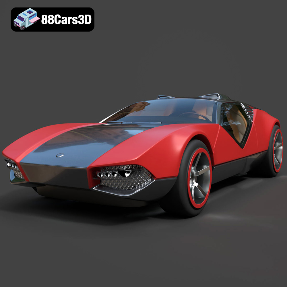
Texture: Yes | Material: Yes
Download the highly detailed, game-ready Hot Wheels La Fasta 3D Model. Features aggressive aerodynamic bodywork, custom racing wheels, and futuristic interior details. Includes .blend, .fbx, .obj, .glb, .stl, .ply, .unreal, and .max formats for game development, AR/VR, and rendering.
Price: $133.00
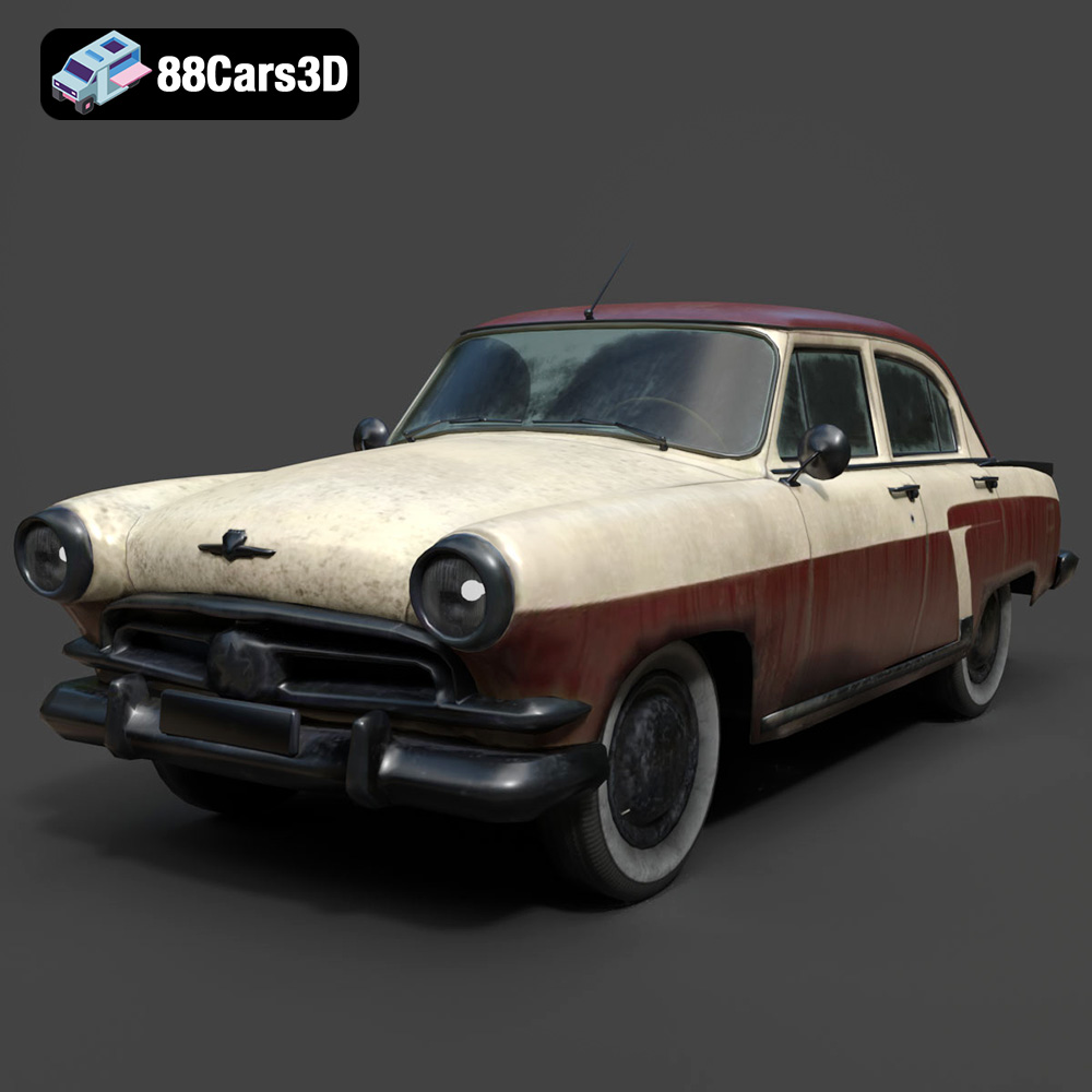
Texture: Yes | Material: Yes
Download the highly detailed, game-ready GAZ-21 Volga 3D Model. Features classic Soviet body geometry, iconic front grille, and detailed exterior chrome accents. Includes .blend, .fbx, .obj, .glb, .stl, .ply, .unreal, and .max formats for game development, AR/VR, and rendering.
Price: $99.99
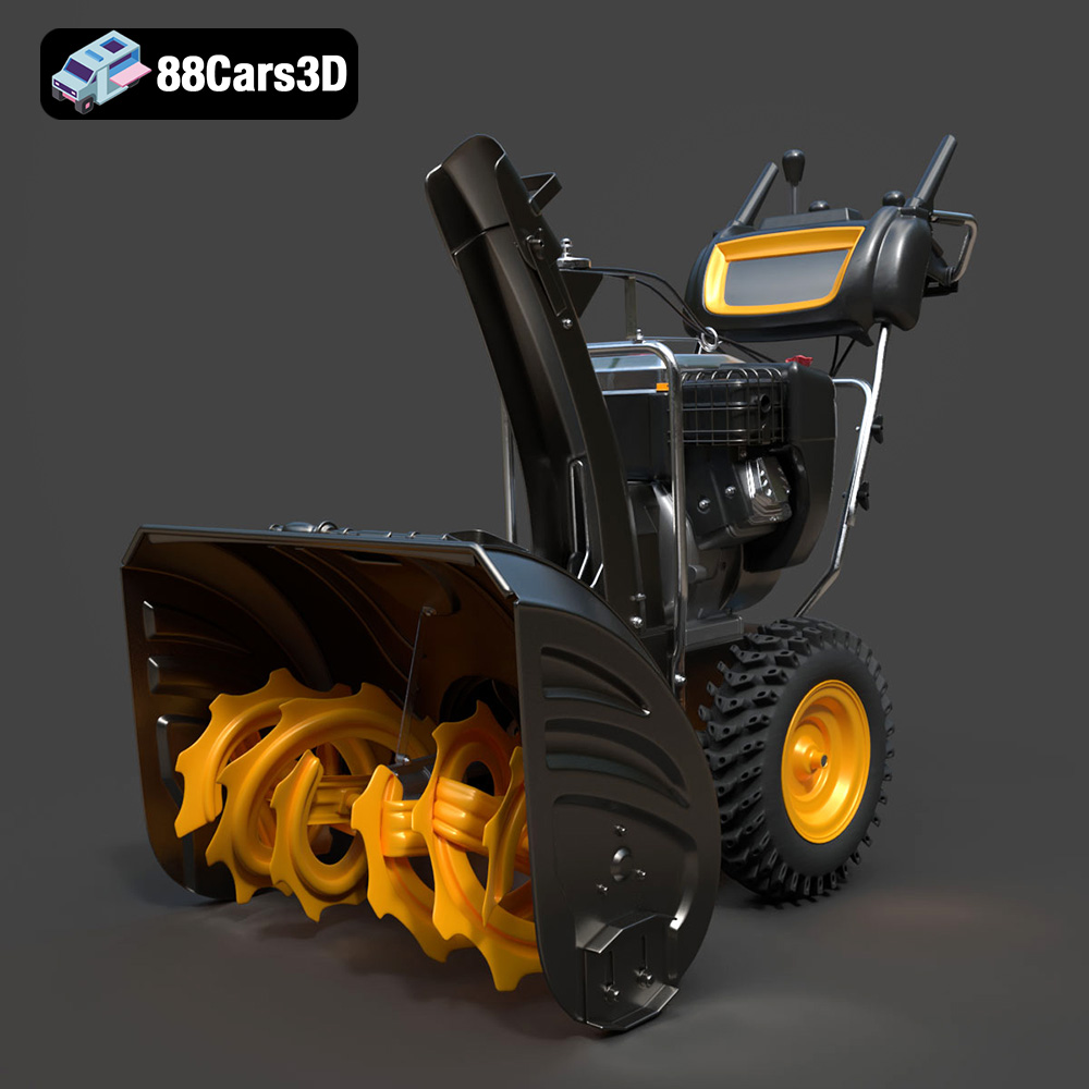
Texture: Yes | Material: Yes
Download the highly detailed, game-ready Husqvarna Snow Plow 3D Model. Features heavy-duty front plow blade, robust chassis, and realistic mechanical controls. Includes .blend, .fbx, .obj, .glb, .stl, .ply, .unreal, and .max formats for game development, AR/VR, and rendering.
Price: $145.50
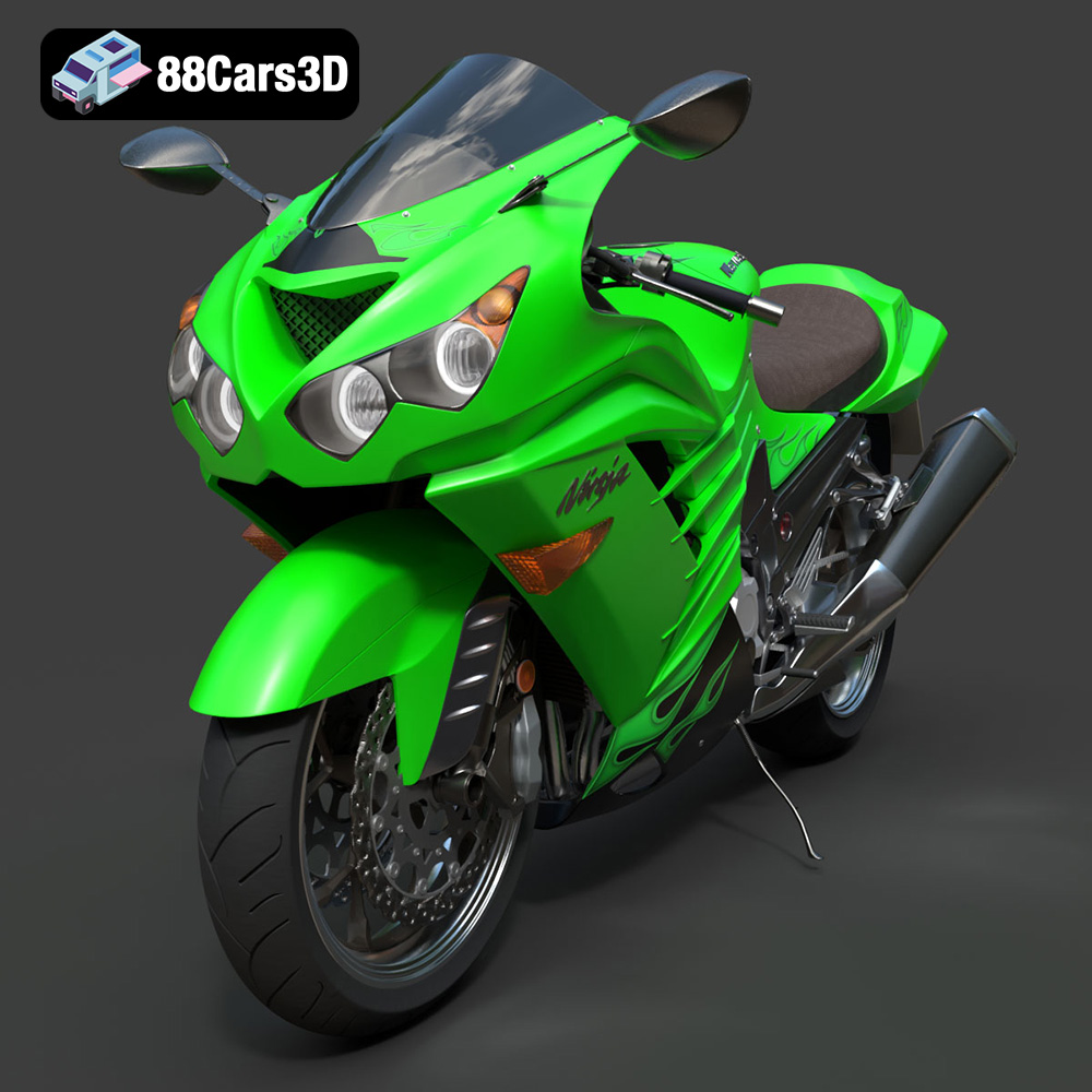
Texture: Yes | Material: Yes
Download the highly detailed, game-ready Kawasaki ZX14R 2012 3D Model. Features aggressive hyper-sport fairings, detailed inline-four engine, and iconic dual exhausts. Includes .blend, .fbx, .obj, .glb, .stl, .ply, .unreal, and .max formats for game development, AR/VR, and rendering.
Price: $170.00
Texture: Yes | Material: Yes
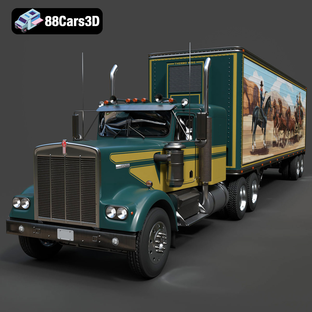
Download the highly detailed, game-ready Kenworth W900 1974 3D Model. Features classic long-nose hood styling, detailed chrome exhaust stacks, and realistic dual tandem axles. Includes .blend, .fbx, .obj, .glb, .stl, .ply, .unreal, and .max formats for game development, AR/VR, and rendering.
Price: $299.50
Texture: Yes | Material: Yes
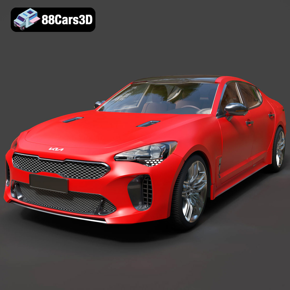
Download the highly detailed, game-ready Kia Stinger 2021 3D Model. Features tiger-nose grille styling, quad exhaust tips, and high-fidelity interior details. Includes .blend, .fbx, .obj, .glb, .stl, .ply, .unreal, and .max formats for game development, AR/VR, and rendering.
Price: $299.50
Texture: Yes | Material: Yes
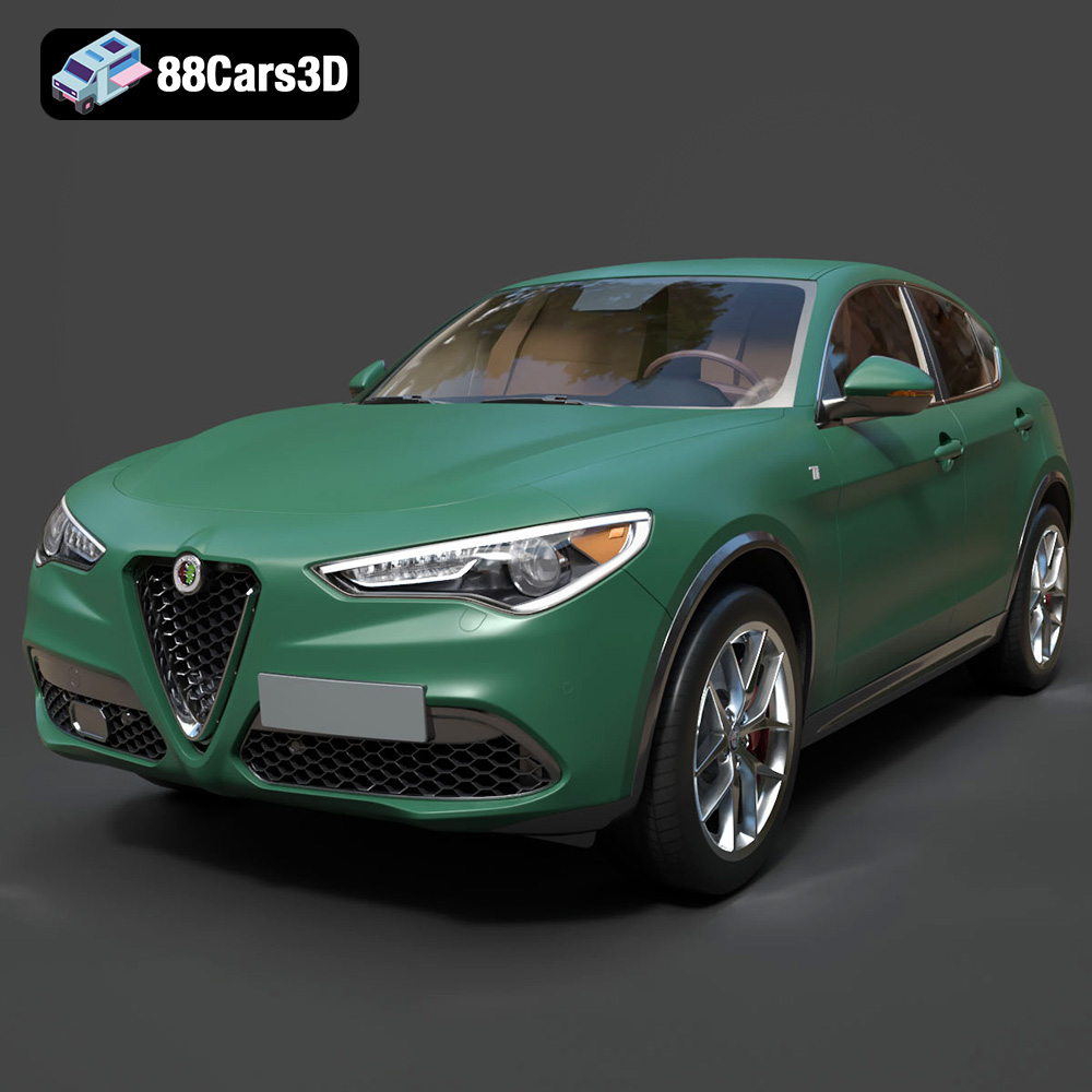
Download the highly detailed, game-ready Alfa Romeo Stelvio Ti 2020 3D Model. Features signature Italian luxury SUV styling, detailed interior, and accurate chassis geometry. Includes .blend, .fbx, .obj, .glb, .stl, .ply, .unreal, and .max formats for game development, AR/VR, and rendering.
Price: $237.99
