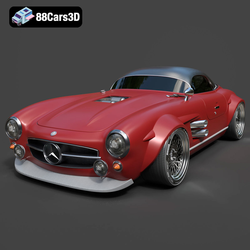
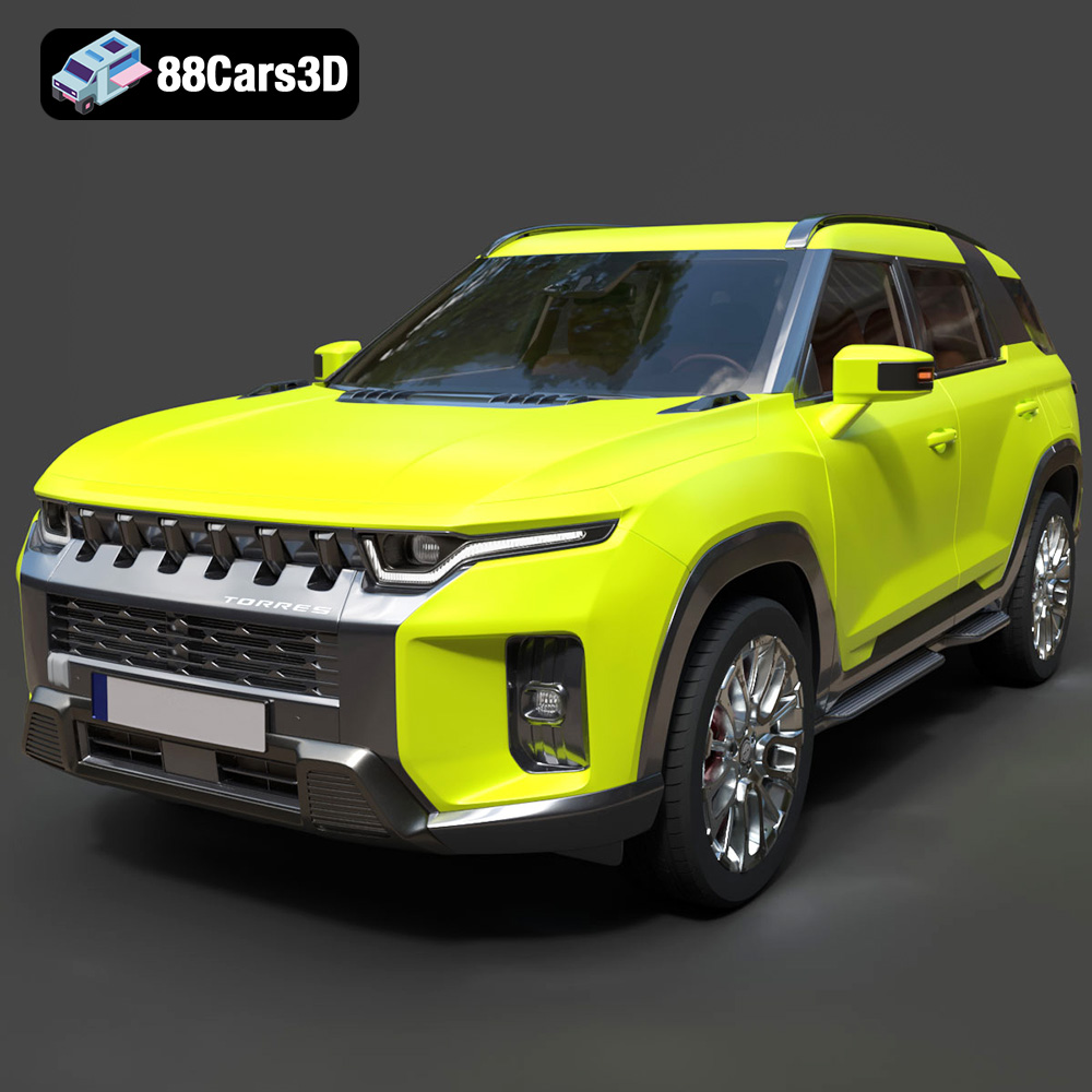
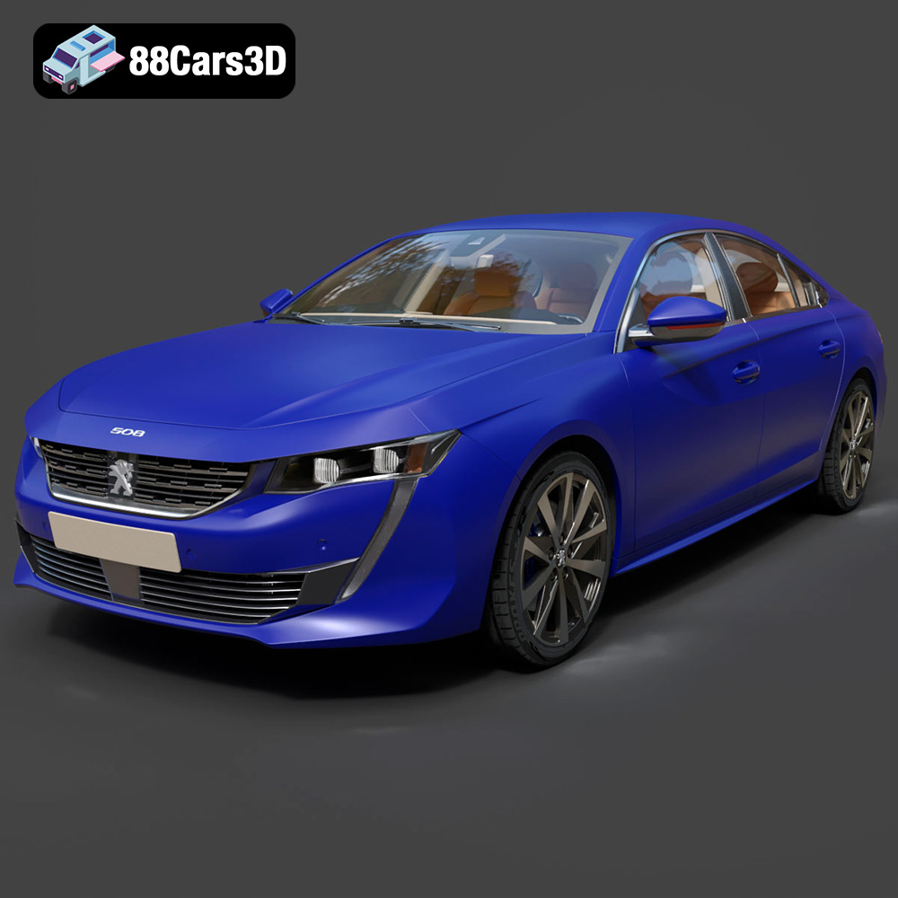
Bringing a static 3D car model to life through animation is one of the most rewarding aspects of 3D artistry. Whether you’re aiming for breathtaking automotive renders, dynamic game cinematics, or interactive AR/VR experiences, a well-constructed rig is the backbone of believable motion. Without a robust and intuitive control system, even the most exquisitely detailed 3D car models remain lifeless sculptures. This comprehensive guide delves deep into the art and science of car rigging in Blender, empowering you to create vehicle animations that truly convey weight, speed, and mechanical integrity. We’ll explore everything from establishing a foundational bone structure to crafting complex suspension systems, ensuring your virtual vehicles perform with photorealistic precision. For those seeking high-quality base models to start their rigging journey, 88cars3d.com offers a vast selection of professional 3D car models perfect for any project.
Understanding 3D Model File Formats
Before diving into the intricacies of rigging, it’s crucial to understand the various file formats you might encounter when acquiring or preparing your 3D car models. Each format serves specific purposes and offers unique advantages for different stages of the 3D pipeline, from initial modeling to final integration into game engines or renderers. Choosing the right format ensures compatibility, preserves data integrity, and optimizes your workflow.
.blend – The Native Blender Ecosystem
- Description: The native file format for Blender projects.
- Use Cases: Ideal for ongoing development within Blender, storing all scene data including meshes, materials, textures, animations, rigging, cameras, lighting, and even custom scripts.
- Technical Details: Fully editable, self-contained, and preserves all Blender-specific data. This means you can open a .blend file and have access to every single parameter and modifier used in its creation. It’s the most flexible format when working exclusively within Blender.
- Compatibility: Primarily for Blender. While other software can sometimes import .blend files with plugins, it’s generally recommended to export to more universal formats for cross-application work.
.fbx – The Industry Standard for Interoperability
- Description: Autodesk Filmbox, a proprietary file format owned by Autodesk, widely adopted across the 3D industry.
- Use Cases: The go-to format for transferring animated 3D models between different software packages, especially crucial for game development (Unreal Engine, Unity), animation pipelines, and motion capture data.
- Technical Details: Supports mesh data, materials, textures, skeletons, skinning (weight painting), and animation curves. It can embed textures, but often links to external texture files. FBX allows for precise control over what data is exported, making it incredibly versatile.
- Compatibility: Excellent for Unreal, Unity, 3ds Max, Maya, Cinema 4D, and most major 3D applications. It’s the bridge format for many real-time pipelines.
.obj – The Universal Mesh Exchange Format
- Description: Wavefront OBJ, a simple and widely supported geometric data file format.
- Use Cases: Best for exchanging static mesh data between different 3D applications. It’s often used when only the geometry and basic UVs are needed, and rigging or animation data is less critical or handled separately.
- Technical Details: Stores vertex positions, UV coordinates, normals, and polygonal faces. It can reference external .mtl (material) files for basic material properties. OBJ is a text-based format, making it human-readable for debugging, but less efficient for very large scenes compared to binary formats.
- Compatibility: Universally compatible. Almost every 3D software can import and export .obj files, making it a reliable choice for mesh sharing.
.glb – Optimized for Web and Interactive Experiences
- Description: GL Transmission Format Binary, the binary version of glTF, specifically designed for efficient transmission and loading of 3D scenes and models.
- Use Cases: Highly optimized for web-based 3D applications, AR (Augmented Reality), VR (Virtual Reality), and browser-based display. It’s becoming the standard for displaying 3D models interactively online.
- Technical Details: A self-contained single binary file that includes geometry, materials, textures, animations, and scene graph information. Its compact nature and efficient parsing make it ideal for real-time applications where performance is critical.
- Compatibility: Excellent for web browsers (via WebGL), AR/VR platforms, and viewers that support the glTF standard.
.stl – The Standard for 3D Printing
- Description: Stereolithography, a widely used file format for 3D printing and computer-aided manufacturing.
- Use Cases: Exclusively for 3D printing output. It defines only the surface geometry of a 3D object using a mesh of triangles.
- Technical Details: Stores only triangular facets that define the surface of the object, without color, texture, or other model attributes. It comes in ASCII and binary forms, with binary being more common due to smaller file size.
- Compatibility: The de facto standard for almost all 3D printing software and hardware.
.ply – Precision Mesh Format for Scan Data
- Description: Polygon File Format or Stanford Triangle Format, used to store graphical objects as a collection of polygons.
- Use Cases: Primarily used for storing 3D scan data and point clouds. It excels when precision geometry or complex vertex attributes (like color per vertex) are important, often used in scientific or industrial applications.
- Technical Details: Can store properties such as color, transparency, surface normals, texture coordinates, and data confidence values, allowing for richer mesh descriptions than .obj. It supports both ASCII and binary formats.
- Compatibility: Supported by many 3D scanning software, CAD programs, and scientific visualization tools.
.unreal – Engine-Ready Asset for Real-Time Environments
- Description: While not a direct export format like .fbx, “.unreal” refers to assets specifically prepared and imported into Unreal Engine, often through the .fbx pipeline.
- Use Cases: Represents a fully integrated asset within Unreal Engine, optimized for its real-time rendering pipeline, physics, and animation system. This includes static meshes, skeletal meshes, materials, and animations ready for game logic.
- Technical Details: After importing an .fbx, Unreal processes the data, creating its own internal assets (Static Mesh, Skeletal Mesh, Material Instances, Animation Sequences). These are then saved within Unreal project files (.uasset).
- Compatibility: Native to Unreal Engine.
.max – The 3ds Max Project File
- Description: The native file format for Autodesk 3ds Max.
- Use Cases: Similar to .blend, it’s for ongoing development within 3ds Max, storing all scene data including models, lights, cameras, modifiers, materials, and animations.
- Technical Details: A proprietary binary file format containing all aspects of a 3ds Max scene. It’s fully editable and preserves the entire history and setup of the project.
- Compatibility: Primarily for 3ds Max. Similar to .blend, it’s best to export to universal formats like .fbx for cross-software compatibility.
Understanding these formats allows you to make informed decisions when sourcing or preparing your 3D car models, ensuring a smooth transition into your rigging and animation pipeline.
The Foundation: Preparing Your 3D Car Model for Rigging
A successful rig begins with a meticulously prepared model. Just as a strong building needs a solid foundation, a dynamic car rig requires clean geometry, correct scale, and a logical object hierarchy. Neglecting these initial steps can lead to frustrating issues down the line, from unpredictable deformations to scale discrepancies in game engines. Many professional 3D car models from 88cars3d.com are already optimized, providing an excellent starting point.
Mesh Optimization and Topology
Rigging relies heavily on the underlying mesh. For organic models, good topology means clean edge loops that follow muscle flow for deformation. For mechanical models like cars, it means sufficient polygon density in areas of movement (like around suspension joints or wheel wells) and efficient geometry elsewhere. Look for:
- Clean Geometry: Ensure there are no N-gons (faces with more than 4 vertices) or non-manifold geometry. Quads are generally preferred, especially for areas that might deform.
- Appropriate Poly Count: For real-time applications (games), aim for optimized poly counts. High-resolution models for cinematic renders can have more detail, but ensure unnecessary subdivisions are removed. For instance, a game-ready vehicle might have 50,000-150,000 polygons, while a cinematic model could easily exceed 500,000.
- Consistent Normals: All face normals should point outwards consistently to avoid rendering artifacts and issues with modifiers.
- Separate Components: The main car body, wheels, brake calipers, steering wheel, and other moving parts should be separate mesh objects. This makes individual component rigging much easier and cleaner. Avoid joining everything into one mesh before rigging.
Setting Up Scene Scale and Origin
Scale is paramount, especially if your model will be exported to a game engine like Unreal Engine or Unity. These engines have specific scale expectations (e.g., 1 unit = 1 meter in Unreal). Consistency prevents assets from appearing too large or too small upon import.
- Real-World Scale: Model your car to real-world dimensions (e.g., a typical sedan might be around 4.8 meters long, 1.8 meters wide, and 1.4 meters tall).
- Apply Transforms: Crucially, after scaling and positioning your model, apply all transforms (Location, Rotation, Scale) to zero out their values. In Blender, this is done by selecting all objects and pressing
Ctrl + A, then choosing “All Transforms.” This ensures that the object’s local origin and scale are consistent, which is vital for correct bone placement and constraint behavior.
- Object Origin: Each separate object (car body, individual wheels) should have its origin point set to a logical location.
- For the main car body: Set the origin to the center of the car, typically at ground level, or slightly above, aligned with the vehicle’s center of mass. This will serve as the pivot for global rotations.
- For each wheel: Set the origin to the center of the wheel’s geometry, exactly where it rotates around its axle. This is critical for accurate wheel spin.
Establishing a Robust Vehicle Skeleton & Control Hierarchy
The skeleton is the core of your rig. It defines the hierarchical relationship between different parts of the car and dictates how they move relative to each other. A well-designed skeleton, complemented by an intuitive control hierarchy, makes animation a fluid and enjoyable process rather than a frustrating battle with pivots and transformations.
Chassis, Body, and Wheel Bone Placement
Start by adding an Armature (Shift + A > Armature > Single Bone) to your scene. This will be the foundation of your car’s “spine.”
- Root Bone (Chassis/Main Controller): This is the absolute parent of your entire car. Place its head at the center of the car (matching the car body’s origin) and its tail pointing upwards. This bone will control the global position and rotation of the vehicle.
- Body Bone: Parented to the Root Bone, this bone directly controls the car’s visual body. It allows for subtle body lean or suspension compression without affecting the overall chassis movement. Place its head at the Root Bone’s head and its tail slightly higher.
- Wheel Axle Bones: For each wheel, create a small bone positioned precisely along the imaginary axle line where the wheel rotates. These bones will serve as the pivot for wheel rotation and steering. They should typically be parented to the Root Bone, allowing them to move with the car but still rotate independently.
- Steering Bones: For front wheels, you’ll need additional bones or a system to control their left-right steering. We’ll detail this further in the steering section, but anticipate bones that pivot at the steering knuckle.
- Suspension Bones (Optional but Recommended): For realistic suspension, you’ll add specific bone chains for each wheel, mimicking the actual suspension components. These will connect the wheel axle to the chassis.
Crafting Intuitive Custom Controls (Empties)
While bones form the skeleton, empties (or custom shapes for bones) provide animators with intuitive handles to manipulate the rig. These controls abstract away the complexity of the underlying bones.
- Main Car Control: A large empty (e.g., a cube or custom shape) around the entire car, parented to the Root Bone (or sometimes the Root Bone itself acts as the main control). This controls the car’s global translation and rotation.
- Wheel Controls: For each wheel, a separate empty, ideally a circle or custom shape aligned with the wheel, placed at the wheel’s origin. These controls will be used to drive individual wheel rotation and potential suspension articulation. These should be parented to their respective axle bones.
- Steering Control: A separate empty or bone at the front of the car, representing a steering wheel. This control will drive the rotation of the front wheel steering bones.
- Suspension Controls: For advanced suspension, you might have empties that act as target points for IK chains, allowing animators to easily adjust ride height or individual wheel articulation.
Parenting and Hierarchy for Predictable Movement
The hierarchy is critical for ensuring movements are predictable and stable. A clear parent-child relationship dictates how transformations propagate through the rig.
- Main Car Control > Root Bone > Body Bone: This is a common setup. The Main Car Control empty controls the Root Bone, which then controls the Body Bone and all other major components.
- Root Bone > Wheel Axle Bones: The wheel axle bones are children of the Root Bone, ensuring they move with the car’s chassis.
- Wheel Axle Bones > Wheel Mesh: The actual 3D wheel mesh objects are parented to their respective Wheel Axle Bones (
Ctrl + P > Bone), meaning they will follow the bone’s movement and rotation.
- Body Bone > Car Body Mesh: The main car body mesh is parented to the Body Bone.
- Steering Control > Steering Bones: The steering control will drive the steering bones, which in turn might influence the front wheel axle bones.
Careful planning of this hierarchy ensures that moving the main car control moves everything, while moving a wheel control only affects that specific wheel, and so on.
Implementing Realistic Wheel Rotation and Steering Mechanics
The wheels are where a car’s motion is most visually evident. Achieving realistic rotation and steering is key to convincing animation. Blender’s drivers and constraints offer powerful tools to automate these complex relationships.
Linking Wheel Rotation to Global Movement (Drivers & Constraints)
Manually keyframing wheel rotation to match the car’s forward motion is tedious and prone to error. Drivers automate this by linking one property (wheel rotation) to another (car’s global movement).
- Calculating Wheel Circumference: First, you need the wheel’s circumference. Measure the radius of your wheel (e.g., 0.35 meters). Circumference = 2 * Pi * Radius. (e.g., 2 * 3.14159 * 0.35 = 2.199 meters). This means for every 2.199 meters the car travels, the wheel completes one full rotation (360 degrees or 2*Pi radians).
- Setting up the Driver:
- Select one of your wheel axle bones (or the wheel control empty).
- Right-click on its Z-rotation property (assuming the wheel rotates around its local Z-axis) in the Transform panel and choose “Add Driver.”
- Open the Driver Editor (or right-click again and “Edit Driver”).
- Type: Change to “Scripted Expression.”
- Expression: Enter something like
(var / circumference) * -2 * pi.
var will be your car’s global movement.circumference is the value you calculated.-2 * pi converts meters traveled into radians (one full rotation). The negative sign might be needed depending on your wheel’s local axis orientation.
- Variables: Add a variable.
- Type: “Transform Channel.”
- Object: Select your main car control (e.g., “Car_Main_Control”).
- Transform Type: “Location.”
- Axis: Choose the axis along which the car moves forward (e.g., “Z Location” or “Y Location”).
- Repeat for all four wheels. Adjust the sign (positive/negative) of
-2 * pi for each wheel if they rotate in the wrong direction.
Building a Functional Steering System (Track To, Drivers)
Realistic steering involves the front wheels turning on their local Z-axis (or appropriate axis) in response to a steering control, and potentially simulating Ackerman steering geometry.
- Steering Bone Setup: For each front wheel, you’ll have a “steering knuckle” bone (e.g., ‘Bone.L.Steer’ and ‘Bone.R.Steer’) parented to its respective wheel axle bone. These bones pivot the front wheel.
- Steering Control Empty: Create an empty (e.g., ‘Steering_Control’) positioned conveniently for the animator, perhaps above the hood.
- Driver for Steering Angle:
- Select ‘Bone.L.Steer’. Right-click its Z-rotation (or relevant axis) and “Add Driver.”
- Type: “Scripted Expression.”
- Expression:
(var * -1) * steering_multiplier (adjust -1 and steering_multiplier as needed).
- Variable: Add a variable.
- Type: “Transform Channel.”
- Object: ‘Steering_Control’.
- Transform Type: “Rotation.”
- Axis: Choose the axis that corresponds to your steering input (e.g., “Z Euler Rotation”).
- Repeat for ‘Bone.R.Steer’, but potentially omit the
-1 multiplier so it rotates in the opposite direction for steering.
- Steering Multiplier: This value allows you to control how much the wheels turn for a given rotation of the ‘Steering_Control’. Experiment to find a natural feel.
- Ackerman Steering (Advanced): For true realism, front wheels don’t turn at the same angle; the inner wheel turns slightly more sharply than the outer wheel. This can be achieved with more complex driver setups or by using constraints that target points dynamically. A simpler approximation involves slightly different
steering_multiplier values for the left and right wheels.
Advanced Considerations: Wheel Spin and Drift
While the basic driver links linear movement to rotation, you might need more control for effects like wheel spin or drift.
- Separate Spin Control: Add a custom property to your main car control called “Wheel_Spin_Multiplier.” Modify your wheel rotation driver expression to include this:
((var * Wheel_Spin_Multiplier) / circumference) * -2 * pi. Now, you can animate “Wheel_Spin_Multiplier” to create burnout effects or simulate loss of traction.
- Drift Influence: For drifting, you would introduce an additional rotation value to the wheel axle bones that is driven by the car’s sideways motion or a dedicated “Drift_Angle” control, blending it with the forward motion rotation. This is often combined with animation of the suspension for body roll.
Rigging Dynamic Suspension Systems for Visual Realism
A static car looks unnatural, especially on uneven terrain. A dynamic suspension system is crucial for simulating the weight and interaction of the car with its environment, adding a layer of authenticity to your automotive rendering.
Basic Suspension: Bone Chains and Constraints
A simple yet effective suspension can be achieved using a short bone chain and a “Limit Location” constraint.
- Setup:
- For each wheel, create a bone chain: a “UpperArm” bone parented to the chassis, and a “LowerArm” bone parented to the UpperArm. The wheel axle bone is then parented to the LowerArm.
- Position these bones to mimic a basic double-wishbone or MacPherson strut setup.
- Constraint:
- Select the LowerArm bone. Add a “Limit Location” bone constraint.
- Define the Z-axis limits (or appropriate axis) to allow the wheel to move up and down within a realistic range, simulating suspension travel. Ensure “Local Space” is selected.
- You can also add a “Copy Location” constraint to the UpperArm bone, targeting a point on the chassis to ensure it follows the body, or simply parent it directly.
- Animating: To animate the suspension, you would typically move the entire car up and down relative to the ground plane, or move the ground plane itself, and the constrained bones would react within their limits.
Advanced IK Suspension for Independent Articulation
For truly realistic and independent wheel articulation, Inverse Kinematics (IK) is the preferred method. IK allows you to control the end of a bone chain (the wheel) and have the intermediate bones (suspension arms) automatically calculate their positions.
- IK Bone Chain Setup:
- For each wheel, create a small bone, e.g., “WheelIK_Target”, and parent it to the main Root Bone. This will be your IK target.
- Create a bone chain representing the suspension arms. For example: “Chassis_Mount” (parented to the car’s body bone) > “Upper_Arm” > “Lower_Arm” > “Spindle” (where the wheel attaches).
- The “WheelIK_Target” should be positioned at the same point as the “Spindle” bone’s head in its default pose.
- Applying IK Constraint:
- Select the “Spindle” bone (the end of the chain).
- Go to the Bone Constraint Properties and add an “Inverse Kinematics” constraint.
- Target: Select your Armature object.
- Bone: Select the “WheelIK_Target” bone.
- Chain Length: Set this to the number of bones in your IK chain (e.g., 3 for Upper_Arm, Lower_Arm, Spindle).
- You may need to adjust Pole Angles for correct knee direction.
- Controlling Suspension: By moving the “WheelIK_Target” empty up and down, you can directly control the vertical position of the wheel, and the suspension bones will articulate realistically. This is excellent for animating over bumpy terrain.
Simulating Terrain Interaction and Dampening
Bringing the suspension to life involves linking the IK targets to the ground, and simulating some dampening effect.
- Ground Raycasting (Advanced, typically in Game Engines): In game engines, raycasts (or line traces) can be used to detect the ground directly below each wheel. The IK target for each wheel would then be moved to the raycast hit point, allowing the wheels to dynamically conform to terrain. While Blender doesn’t have native real-time raycasting for rigging, you can simulate this in animation by manually keyframing the IK targets to follow an uneven path object.
- Soft Suspension using IK Limits: You can add “Limit Location” constraints to your IK target empties or directly to the IK bones to simulate spring compression limits. Drivers can also be used to create a “spring” effect, where moving the car body down pushes the wheels down, and moving it up allows them to extend, with a bit of “bounce.”
- Body Roll: For even more realism, parent your Body Bone to a separate “Car_Pivot” bone that is itself parented to the Root Bone. Add “Limit Rotation” constraints to the Body Bone to allow it to tilt slightly on the X and Y axes, mimicking body roll during turns or weight transfer during acceleration/braking. This can be driven by the car’s acceleration or steering angle.
Integration and Refinement: Bringing Your Rig to Life
With the core skeleton and controls in place, the final steps involve ensuring smooth deformation, preparing for animation, and considering export options for different platforms.
Weight Painting and Deformation Considerations
Weight painting defines how much influence each bone has over specific vertices of a mesh. While car bodies are largely rigid, some areas might require subtle deformation, especially with suspension and internal elements.
- Rigid Parent/Child: For most car components (body, wheels, brake calipers), simple parent-child relationships are sufficient (
Ctrl + P > Bone). There’s no need for complex weight painting if the mesh doesn’t deform.
- Subtle Deformations: If you have parts that slightly bend or compress (e.g., rubber tires, flexible trim), you might parent them with automatic weights or manually paint weights to allow for slight deformation. Ensure that 100% of a vertex’s weight is assigned to a bone, and that weights are smoothly transitioning between bones where deformation is intended.
- Checking for Issues: After parenting meshes to bones (with or without weights), move your controls through their full range of motion to identify any tearing, stretching, or unwanted deformations. Adjust weights or bone positions as needed.
Animation Principles and Workflow Tips
A robust rig is only as good as the animation it produces. Adhering to fundamental animation principles will elevate your car’s performance.
- Keyframe Everything: Use keyframes on your control empties and custom bone properties (like wheel spin multiplier, steering angle).
- Graph Editor: Master Blender’s Graph Editor. It allows you to refine animation curves, smooth out transitions, and apply easing for acceleration, deceleration, and turns, giving motion a natural, physical feel.
- Arcs and Overlap: Even rigid objects follow arcs. For instance, the main body might slightly arc when turning. Overlap can be subtle but effective: the body might settle slightly after a sudden stop or turn.
- Secondary Motion: Don’t forget small details. A subtle vibration of the exhaust, slight movement of an antenna, or a bit of engine shake can add significant realism. These can often be achieved with simple bone constraints or procedural modifiers.
- Timing and Spacing: How quickly or slowly something moves (timing) and the distance it covers between frames (spacing) are crucial for conveying speed, weight, and impact.
- Reference Footage: Always use real-world video references of cars in motion to inform your animation. Observe how suspension reacts, how wheels turn, and how the body shifts weight.
Exporting Your Rigged Model for Other Platforms
Once your car is rigged and ready for animation, you’ll likely need to export it for use in other software, particularly game engines or other rendering packages.
- FBX for Game Engines: The .fbx format is the industry standard for exporting rigged and animated models to game engines like Unreal Engine and Unity.
- Blender Export Settings: When exporting from Blender (File > Export > FBX), ensure you select “Armature” and “Mesh” under “Object Types.” Check “Apply Transforms” and “Bake Animation” if you’ve already animated. Crucially, ensure “Scale” is set correctly (e.g., 0.01 for Unreal Engine if your Blender unit is 1 meter and Unreal’s is 1 cm).
- Unreal Engine Considerations: When importing into Unreal, choose “Skeletal Mesh” and ensure “Import Animations” is checked if applicable. You’ll typically get the mesh, skeleton, and animations as separate assets.
- GLB for Web/AR/VR: For interactive web experiences or AR/VR applications, .glb is an excellent choice due to its optimization. Blender’s glTF exporter handles skeletal meshes and animations well.
- OBJ (Static): If you only need the static mesh without the rig, .obj remains a universal choice for its broad compatibility.
Conclusion
Mastering car rigging in Blender is a transformative skill that unlocks the full potential of your 3D car models. From laying down the foundational bone structure to implementing intricate wheel mechanics and dynamic suspension systems, each step contributes to creating animations that are not just visually appealing, but also technically sound and believable. By leveraging Blender’s powerful tools—bones, empties, drivers, and constraints—you can build robust and animator-friendly rigs that breathe life into your virtual vehicles. Remember that preparation is key; a clean, optimized model forms the best canvas for your rigging efforts. For artists and studios seeking to elevate their automotive projects with high-quality, pre-optimized 3D car models, 88cars3d.com provides an unparalleled resource. Dive in, experiment, and enjoy the journey of bringing your automotive visions from still frames to compelling motion.
Featured 3D Car Models