
Creating truly convincing automotive renders hinges on one crucial element: the car paint material. Far from a simple color application, realistic car paint is a complex interplay of reflective layers, metallic flakes, subtle imperfections, and environmental interactions. For 3D artists, game developers, and automotive designers, mastering this material is essential for producing high-fidelity visualizations that capture the sleekness and luxury of a vehicle. This comprehensive guide will delve deep into Blender’s Shader Editor, providing you with the technical knowledge and practical workflows to craft stunningly realistic car paint materials. We’ll explore Physically Based Rendering (PBR) principles, dissect the anatomy of automotive paint, and guide you through setting up advanced effects, ensuring your 3D car models achieve photorealistic brilliance whether for static renders, interactive experiences, or cinematic animations. By the end of this article, you’ll possess the expertise to elevate your 3D automotive projects to a professional standard, ready for platforms like 88cars3d.com.
Physically Based Rendering (PBR) has revolutionized 3D graphics by accurately simulating how light interacts with surfaces, resulting in far more believable materials. For car paint, PBR is not just a guideline; it’s the bedrock of realism. At its core, PBR relies on a set of material properties that are based on real-world physics, ensuring that materials look consistent under various lighting conditions. Understanding these properties – Albedo (Base Color), Metallic, Roughness, Normal, and Clearcoat – is paramount.
Car paint is inherently complex, comprising multiple layers. The underlying pigment and metallic flake layer (often referred to as the base coat) provides the primary color and shimmering effect, while a transparent, highly reflective clear coat protects the base and provides the signature gloss. This layered structure means light interacts with the material in multiple ways: some light is absorbed and reflected by the base coat, while other light reflects directly off the clear coat’s surface. The Principled BSDF shader in Blender is an incredibly powerful tool for PBR workflows, encapsulating many of these properties into a single, intuitive node. Its design allows artists to focus on physical attributes rather than complex shader graphs from scratch, making it ideal for crafting sophisticated materials like car paint.
The complexity of car paint can be broken down into two primary layers: the base coat and the clear coat. The **base coat** is where the vehicle’s primary color is defined. This layer typically contains pigment (the actual color), and in most automotive finishes, microscopic metallic or pearlescent flakes. These flakes are responsible for the sparkling effect and how the paint shifts color or brightness depending on the viewing angle. The metallic property in a PBR workflow dictates how much of the diffuse color is treated as a reflective surface versus a colored dielectric. A higher metallic value means more light is reflected as specular, contributing to the distinct sheen of automotive paint. Roughness on this base layer determines how blurred or sharp these reflections are, influencing the perceived “wetness” or texture of the underlying paint.
Above the base coat lies the **clear coat**, a transparent, highly glossy layer of lacquer. This layer is primarily responsible for the mirror-like reflections and deep shine characteristic of new car paint. From a PBR perspective, the clear coat acts as a separate dielectric layer with its own set of reflective properties. It has its own roughness value, dictating the sharpness of its reflections, and a critical Index of Refraction (IOR). The IOR determines how much light bends and reflects off the clear coat surface, affecting both the intensity of reflections and the visual depth of the paint. The clear coat also imparts subtle Fresnel effects, where reflections become more intense at glancing angles, mimicking real-world behavior. The interaction between these layers is crucial: light passes through the clear coat, interacts with the base coat, and then passes back through the clear coat to the viewer’s eye, with reflections occurring at both interfaces.
Achieving photorealistic car paint hinges on accurately calibrating PBR values. A common pitfall for beginners is making materials too rough or too metallic, leading to an unrealistic, “plasticky” or overly shiny look. For the clear coat, the **IOR (Index of Refraction)** is a fundamental parameter. While a default IOR of 1.450 for dielectric materials is often a good starting point in Blender’s Principled BSDF, real automotive clear coats can range from 1.4 to 1.55 depending on their chemical composition. Experimenting within this range will yield subtle yet significant differences in how light reflects. A higher IOR generally results in stronger, more pronounced reflections.
For **roughness**, remember that nothing in the real world is perfectly smooth. Even the most polished car paint will have microscopic imperfections that scatter light, introducing a degree of roughness. For the clear coat, a subtle roughness value between 0.01 and 0.05 is often appropriate for a new, glossy finish. Introducing a very slight texture map (e.g., a subtle noise texture) to the clear coat roughness input can break up perfectly uniform reflections, adding to the realism. For the base coat, if it’s a metallic paint, its roughness will typically be slightly higher than the clear coat, reflecting the light scattering from the metallic flakes. The **metallic** value should be set to 1 for the base layer, indicating that the base coat’s color is being treated as a metal for reflection purposes, with the clear coat acting as an additional dielectric layer on top. By paying close attention to these values and using real-world references, you can avoid common issues and achieve a compellingly realistic finish.
The base coat is the heart of your car paint material, defining its primary color and the mesmerizing glint of its metallic or pearlescent particles. In Blender’s Shader Editor, we start with the **Principled BSDF** node, which provides a comprehensive set of parameters for physically accurate materials. Set the **Base Color** to your desired automotive hue – blues, reds, silvers, or blacks are common choices. For metallic paints, the **Metallic** slider should be set to 1. This is crucial because it tells the shader to treat the Base Color as the color of a metal, generating metallic reflections rather than a simple diffuse color.
The magic of metallic car paint, however, lies in its flakes. These tiny, reflective particles embedded within the base coat catch the light and create that characteristic sparkle and depth. While the Principled BSDF handles the general metallic properties, achieving truly convincing flakes often requires a more advanced approach. We can simulate these flakes using procedural textures, which offer immense control and flexibility without needing external image textures. The key is to generate a fine, scattered pattern that influences the normal of the base layer, making individual “flakes” reflect light differently. This procedural approach, combined with the right roughness and anisotropic settings, will give your base coat a dynamic and realistic appearance, a vital aspect for any high-quality 3D car model.
Creating convincing metallic flakes procedurally in Blender’s Shader Editor involves combining several nodes to generate a detailed, randomized pattern that subtly affects the surface normals. One effective method utilizes the **Voronoi Texture** node. Start by adding a `Voronoi Texture` node and connect its `Distance` output to a `ColorRamp` node. Adjust the `ColorRamp` to create sharp, contrasting black and white values, representing the individual flakes. Setting the `Voronoi Texture` to `F1` or `F2` and increasing the `Scale` significantly (e.g., 200-500 or even higher for very fine flakes) will create a microscopic, granular pattern.
Next, this pattern needs to influence the normals. Connect the `ColorRamp` output to a `Bump` node’s `Height` input. Crucially, set the `Strength` of the `Bump` node to a very low value (e.g., 0.01 to 0.05). This subtle bump map will simulate the individual flakes slightly catching the light. Finally, connect the `Normal` output of the `Bump` node to the `Normal` input of the `Principled BSDF` shader. For enhanced control over flake distribution and appearance, you can mix multiple Voronoi textures with different scales and roughness values using `Mix RGB` nodes set to `Multiply` or `Screen` blend modes. Remember to keep the `Distance` output of the `Voronoi Texture` set to `Distance` and not `Color` for height information. For more in-depth information on procedural textures and node setups, refer to the official Blender 4.4 documentation on [Shader Nodes](https://docs.blender.org/manual/en/4.4/render/shader_nodes/index.html). The goal is to create a subtle but noticeable scattering effect, where the flakes appear to glint as the light or camera moves.
Anisotropy is a subtle yet powerful effect that can significantly enhance the realism of metallic car paints, particularly those with a directional brushed metal look or very fine, aligned flakes. In essence, anisotropic reflections occur when light reflects differently depending on the orientation of microscopic grooves or textures on a surface. Instead of perfectly circular reflections, you see stretched, elliptical highlights that change direction as the object rotates or the viewing angle changes.
To implement anisotropy in Blender’s Principled BSDF, you’ll utilize the **Anisotropic** and **Anisotropic Rotation** inputs. First, increase the `Anisotropic` value to introduce the effect (a value between 0.5 and 1.0 is a good starting point). Next, to control the direction of this stretching, you’ll need a **Tangent** node. Add an `Input` > `Tangent` node. This node provides a vector that defines the direction of the anisotropy. You can either leave it on its default `UV Map` mode (if your UVs are appropriately unwrapped to define a directional flow) or switch it to `Radial` or `Planar` for more generic directional control. Connect the `Tangent` node’s output to the `Tangent` input of the `Principled BSDF`. To rotate these anisotropic reflections, you can manipulate the `Anisotropic Rotation` value. Often, a `Texture Coordinate` node with a `Separate XYZ` and `Combine XYZ` node, or even a `Vector Rotate` node, can be used to drive the `Anisotropic Rotation` input with a texture or procedural noise, adding subtle variations to the flake’s orientation. This subtle directional sheen is crucial for replicating the complex light scattering seen on real automotive finishes, adding a layer of depth that a purely isotropic reflection cannot provide.
The clear coat is arguably the most visually impactful layer of automotive paint, responsible for that deep, wet look and mirror-like reflections that capture the surrounding environment. In Blender’s Principled BSDF shader, the clear coat properties are handled by a dedicated set of inputs: **Clearcoat**, **Clearcoat Roughness**, and **Clearcoat Normal**. Enabling the `Clearcoat` slider (typically set to 1.0 for full effect) activates this top, transparent layer. Its function is to sit atop your base coat, providing an additional layer of reflection and gloss.
The `Clearcoat Roughness` is crucial for defining the sharpness of these reflections. A perfectly smooth clear coat would have a roughness of 0, resulting in razor-sharp, undistorted reflections. However, in reality, even freshly polished paint exhibits microscopic imperfections that scatter light ever so slightly, so a very low value (e.g., 0.01 to 0.05) is usually more realistic than a pure zero. A subtle noise texture connected to this input can also introduce natural variations, breaking up uniform reflections. Furthermore, the **Index of Refraction (IOR)** of the clear coat plays a significant role in how light interacts with its surface. While not directly exposed as an IOR input for the clear coat in the Principled BSDF, its reflective properties are governed by an internal approximation. For general PBR usage, the clear coat in Principled BSDF functions effectively without explicit IOR control, focusing instead on its reflective strength and roughness. The overall IOR of the material (under the ‘Specular’ input’s control) will affect the general dielectric reflections, but the clear coat acts as a distinct, additional layer of reflectivity.
While the Principled BSDF’s Clearcoat input doesn’t offer a direct IOR slider, the overall IOR of the material is implicitly controlled by the `Specular` input, which is driven by the internal PBR calculations for dielectric materials. For realistic clear coat reflections, the standard dielectric F0 (reflectance at normal incidence) value is used, which correlates to an IOR of approximately 1.5. This provides a good baseline for most automotive finishes. If you desire more explicit control over the clear coat’s IOR, you would need to construct a more complex layered shader setup using a `Mix Shader` node with a `Fresnel` node to blend between a transparent BSDF and a glossy BSDF, mimicking the clear coat’s behavior. However, for the vast majority of cases, the Principled BSDF’s built-in clear coat provides excellent results, simplifying the node tree considerably.
The **Clearcoat Roughness** input is where you have direct control over the sharpness of the clear coat’s reflections. As mentioned, a perfectly smooth surface rarely exists in the real world. For a brand new, highly polished car, a `Clearcoat Roughness` value between 0.01 and 0.03 is a good starting point. To add subtle realism, connect a very fine `Noise Texture` or `Musgrave Texture` (with high scale and low detail/lacunarity) to the `Clearcoat Roughness` input. This will introduce micro-variations in the surface, preventing overly perfect, CGI-like reflections. Use a `ColorRamp` node after the texture to fine-tune the range of roughness values, keeping them very low to maintain the high gloss. Remember that excessive roughness will dull the clear coat, making the paint appear less polished. The goal is a subtle scattering that breaks up reflections just enough to make them believable without sacrificing gloss.
Even the most pristine car paint isn’t perfectly flat at a microscopic level. It often exhibits a subtle texture known as “orange peel” – a slight waviness resembling the skin of an orange – a result of the painting process. Additionally, micro-scratches are an unavoidable reality of vehicle ownership. Both of these imperfections, when subtly simulated, can significantly enhance the realism of your car paint.
To create an orange peel effect, you can use a procedural texture to influence the **Clearcoat Normal** input of the Principled BSDF. A `Noise Texture` with a high `Scale` (e.g., 50-100), low `Detail`, and varying `Distortion` can generate a good base pattern. Connect this `Noise Texture` to a `Bump` node’s `Height` input. Crucially, set the `Strength` of the `Bump` node to an extremely low value, typically between 0.005 and 0.02. This ensures the effect is subtle and doesn’t make the paint look heavily textured. Connect the `Normal` output of the `Bump` node to the `Clearcoat Normal` input. For adding micro-scratches, you can layer another `Noise Texture` or even a `Wave Texture` (with very thin lines) and combine it with the orange peel bump map using a `Mix RGB` node set to `Add` or `Multiply`. Alternatively, source a high-quality micro-scratch normal map or even a grunge map and connect it to another `Bump` node, blending its output with your orange peel normal map before feeding it into the Clearcoat Normal. Remember, subtlety is key here; these imperfections should only be visible at very close inspection or when light hits the surface at specific angles, revealing the intricate texture of the paint.
Beyond the fundamental base and clear coat layers, realistic car paint often benefits from additional layers of detail and subtle imperfections that tell a story. Integrating elements like dirt, grime, and edge wear can transform a pristine render into a believable scene, grounded in the wear and tear of real-world use. Furthermore, unique paint types, such as pearlescent or iridescent finishes, require specialized shader setups to achieve their characteristic color-shifting properties. These advanced effects move beyond simple PBR material properties and often involve layering multiple shaders and using complex mask textures to control their distribution.
Adding subtle environmental elements like dust or water spots can also elevate realism, making the car feel integrated into its environment rather than existing in a vacuum. These details are often created by mixing different shaders based on masks, which can be procedural, painted, or generated from geometry data like ambient occlusion. For instance, simulating a multi-layer paint effect for a pearlescent finish might involve blending different colored glossy shaders based on the viewing angle using a Fresnel node. While complex, these techniques offer immense creative control and allow artists to push the boundaries of realism, crafting automotive materials that are not just visually appealing but also rich in narrative detail.
No car stays perfectly pristine forever. Adding subtle dirt, dust, and grime can dramatically increase realism, grounding your 3D car model in its environment. The most effective way to achieve this is by layering a separate “dirt” shader over your car paint shader using a `Mix Shader` node. First, create a basic dirt material: a `Principled BSDF` with a dark, desaturated brown or grey `Base Color`, increased `Roughness` (to simulate dry dirt), and zero `Metallic`.
To blend this dirt shader with your car paint, connect your car paint shader to one input of a `Mix Shader` and the dirt shader to the other. The crucial element here is the `Fac` (Factor) input of the `Mix Shader`, which acts as a mask. For realistic dirt accumulation, you want dirt to gather in crevices, under ledges, and on horizontal surfaces. A great way to achieve this procedurally is using an `Ambient Occlusion` node or the `Geometry` node’s `Pointiness` output. Connect either of these to a `ColorRamp` node to control the falloff and intensity of the dirt mask. You can also use a `Noise Texture` or a `Grunge Texture` (with a `ColorRamp` to make it high contrast) to create a more patchy, uneven dirt distribution. Blend these masks together using `Mix RGB` nodes before feeding them into the `Mix Shader`’s `Fac` input. Remember to keep the dirt effect subtle; often, less is more. The goal is to suggest accumulated grime, not to entirely obscure the beautiful car paint.
Edge wear and more prominent scratches further enhance the narrative of your 3D car model, indicating usage and age. These effects are also best achieved by blending shaders using masks, where the masks selectively reveal an underlying “worn” or “damaged” material. For edge wear, the `Geometry` node’s **Pointiness** attribute is incredibly useful. This attribute generates a mask based on the curvature of your mesh, highlighting sharp edges – perfect for showing paint chipping or abrasion. Connect the `Pointiness` output to a `ColorRamp` node to refine the edge selection, making it as subtle or aggressive as needed.
Create a separate “worn metal” or “primer” shader: a `Principled BSDF` with a metallic grey `Base Color`, higher `Metallic` for exposed metal, and possibly a slightly higher `Roughness`. Mix this shader with your primary car paint shader using a `Mix Shader` and use the `Pointiness` mask as the `Fac` input. For scratches, you’ll generally need texture maps. Look for high-resolution scratch textures or create them procedurally using a `Noise Texture` with very high `Scale` and a `ColorRamp` to create thin lines. These scratch masks can then be used in the same way, mixing an underlying “scratched paint” or “exposed metal” shader. For even greater control, you can combine multiple masks using `Mix RGB` nodes set to `Multiply` or `Screen`. This layered approach allows for a highly detailed and believable portrayal of damage and wear, making your automotive visualizations more dynamic and lifelike.
Even the most meticulously crafted car paint material will fall flat without appropriate lighting and environmental context. Lighting is paramount; it’s what defines the form, highlights the reflections, and dictates the mood of your automotive render. For realistic car renders, **High Dynamic Range Imaging (HDRI)** is almost always the go-to solution. HDRIs provide both illumination and complex environmental reflections, mimicking real-world conditions with unparalleled accuracy. Whether it’s a sunny outdoor scene or a subtle studio setup, the HDRI will literally reflect in your car’s glossy clear coat, making it look integrated into the scene.
Beyond global illumination from HDRIs, strategic accent lighting can further enhance your vehicle’s contours and paint finish. Consider rim lights to define edges or soft box lights to create elegant highlights. The rendering engine also plays a critical role. Blender’s Cycles is a physically accurate ray-tracing engine, excelling at photorealistic results, while EEVEE, its real-time renderer, offers impressive speed for interactive visualizations. Finally, **post-processing** in Blender’s compositor is the crucial final step, allowing you to fine-tune colors, add cinematic effects, and correct any minor imperfections, elevating your render from a raw image to a professional-grade visualization.
HDRIs are an indispensable tool for achieving realistic car renders in Blender. They are 360-degree panoramic images that contain a vast range of light information, from the darkest shadows to the brightest highlights, allowing them to accurately illuminate your scene and provide incredibly convincing reflections on your car’s surface. To use an HDRI in Blender’s Cycles or EEVEE, navigate to the **Shader Editor**, switch the shader type from `Object` to `World`. Add an `Environment Texture` node, open your desired HDRI file, and connect its `Color` output to the `Background` node’s `Color` input.
The choice of HDRI significantly impacts the final look. For a classic studio render, a studio HDRI with softboxes and diffusers will produce elegant, controlled reflections. For outdoor scenes, a high-quality outdoor HDRI (e.g., a cloudy sky, a city street, or a forest) will provide realistic environmental reflections and lighting. Don’t be afraid to experiment with different HDRIs. You can rotate the HDRI within the `World` shader by adding a `Mapping` node and a `Texture Coordinate` node (set to `Environment Texture`) between the `Environment Texture` and `Background` nodes, then adjusting the `Z Rotation` in the `Mapping` node. This allows you to find the perfect angle where the environment’s reflections interact most appealingly with your car paint, highlighting its curves and gloss. Platforms like HDRI Haven (Poly Haven) offer a vast collection of free, high-quality HDRIs for various lighting scenarios.
Post-processing in Blender’s **Compositor** is the final, essential stage in creating a professional automotive render. It’s where you add those subtle cinematic touches, perform color corrections, and enhance the overall visual appeal. Instead of simply relying on the raw render output, the Compositor allows you to manipulate various render passes (such as `Diffuse`, `Glossy`, `Shadow`, `Ambient Occlusion`, `Depth`, etc.) to gain granular control over your final image. To enable render passes, go to the `View Layer Properties` panel and check the passes you wish to use (e.g., `Diffuse Direct`, `Glossy Direct`, `Combined`).
In the Compositor, start by enabling `Use Nodes`. Your `Render Layers` node will now output the selected passes. Common post-processing techniques include:
By combining these nodes and adjusting their parameters, you can transform a good render into a stunning one, giving it a polished, professional finish that is often seen in high-end automotive advertisements and visualizations.
While our focus has been on achieving ultimate realism for car paint, it’s equally important to consider the underlying 3D model, especially when preparing assets for diverse applications like game development, AR/VR, or detailed visualization. A high-quality 3D car model, whether sourced from marketplaces like 88cars3d.com or created from scratch, adheres to specific best practices for topology, UV mapping, and overall efficiency. These factors directly impact how well your meticulously crafted materials will display and perform across different platforms.
Clean topology, characterized by quads and efficient edge flow, is crucial for smooth deformations and proper subdivision. Optimal UV mapping ensures textures, including those that influence procedural flakes and imperfections, are applied without distortion. For interactive applications like game engines, additional optimization strategies come into play, such as Level of Detail (LODs) and efficient texture packing. These considerations ensure that your visually stunning car paint materials can be rendered smoothly and efficiently, regardless of the target platform, making your 3D models versatile and production-ready.
UV mapping is the process of unwrapping the 3D surface of your model into a 2D space, allowing you to apply 2D textures (like color maps, normal maps, or masks) accurately. For complex automotive surfaces, efficient UV mapping is critical for the seamless application of your car paint textures, including the procedural flake patterns, dirt masks, and micro-scratches discussed earlier. Poor UVs can lead to stretching, seams, or distorted texture projection, undermining all your efforts in shader creation.
When UV mapping a car body, aim for contiguous islands with minimal distortion. Smart UV Project can be a quick start, but manual unwrapping, often by marking seams along natural breaks in the geometry (e.g., panel lines, hidden edges), will yield superior results. Pay particular attention to large, curved surfaces like the hood, roof, and doors, ensuring they have ample UV space and are unwrapped as flatly as possible to prevent texture stretching. For texture maps that influence procedural flakes or orange peel, ensuring a consistent texture density across the model is important so the imperfections appear uniform. Overlapping UVs can be acceptable for mirrored parts or if you’re using tiling textures, but avoid them if unique texture details are required. Good UV hygiene is a foundational practice that ensures your carefully crafted car paint materials will look their best.
When your stunning 3D car models, complete with their realistic car paint, are destined for real-time game engines like Unity or Unreal Engine, performance becomes a paramount concern. While high-polygon models and complex shader graphs are acceptable for offline rendering, game environments demand efficiency to maintain smooth frame rates. One of the primary strategies is **Level of Detail (LODs)**. LODs are simplified versions of your model that automatically switch out as the camera moves further away. This means a high-detail model is used up close, while lower-polygon versions are rendered at a distance, drastically reducing the computational load.
Another key optimization is **texture atlasing** and **material consolidation**. Instead of having multiple small textures for different parts of the car and multiple materials, combine related textures into a single, larger texture atlas. Similarly, aim to consolidate as many parts of the car as possible into a single material. This reduces the number of draw calls (instructions sent to the GPU to render an object), which is a significant performance bottleneck in game engines. Baking high-resolution details (like sculpted body lines or intricate panel gaps) into normal maps is also crucial. This allows you to use a lower-polygon mesh while retaining the visual fidelity of a high-poly model, making your 3D car models from platforms like 88cars3d.com game-ready and performant without sacrificing visual quality.
Crafting realistic car paint in Blender’s Shader Editor is an intricate art form, demanding a blend of technical understanding and artistic intuition. We’ve journeyed through the complexities of PBR principles, dissecting the multi-layered nature of automotive finishes, from the vibrant base coat and its shimmering metallic flakes to the glossy, protective clear coat and its subtle imperfections. You’ve learned how to leverage Blender’s powerful Principled BSDF shader, combine procedural textures for dynamic flake generation, and introduce nuanced details like orange peel and micro-scratches. We also explored the critical role of lighting and environment, particularly HDRIs, and the transformative power of post-processing in the Compositor to achieve professional-grade renders.
Remember that the pursuit of realism is an ongoing process of experimentation and refinement. Don’t hesitate to iterate on your shader settings, test different lighting conditions, and compare your results with real-world automotive photography. The techniques outlined in this guide provide a robust foundation for creating visually stunning 3D car models. By applying these principles, you’ll not only enhance the visual appeal of your automotive visualizations but also gain a deeper appreciation for the interplay of light, material, and environment. Continue to explore, innovate, and bring your automotive designs to life with unparalleled realism. For high-quality base models to apply your newfound shader mastery, consider exploring the extensive collection of 3D car models available on 88cars3d.com.
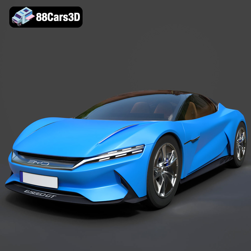
Texture: Yes | Material: Yes
Download the highly detailed, game-ready BYD e-SEED GT 2019 3D Model. Features futuristic gull-wing doors, sleek aerodynamic electric supercar silhouette, and detailed LED light strips. Includes .blend, .fbx, .obj, .glb, .stl, .ply, .unreal, and .max formats for game development, AR/VR, and rendering.
Price: $194.50
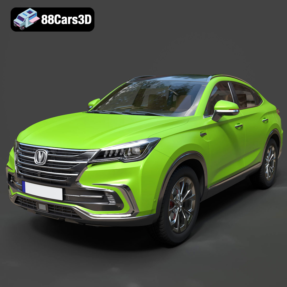
Texture: Yes | Material: Yes
Download the highly detailed, game-ready Changan CS85 Coupe 2019 3D Model. Features sleek fastback SUV styling, detailed front grille, and realistic lighting. Includes .blend, .fbx, .obj, .glb, .stl, .ply, .unreal, and .max formats for game development, AR/VR, and rendering.
Price: $275.00
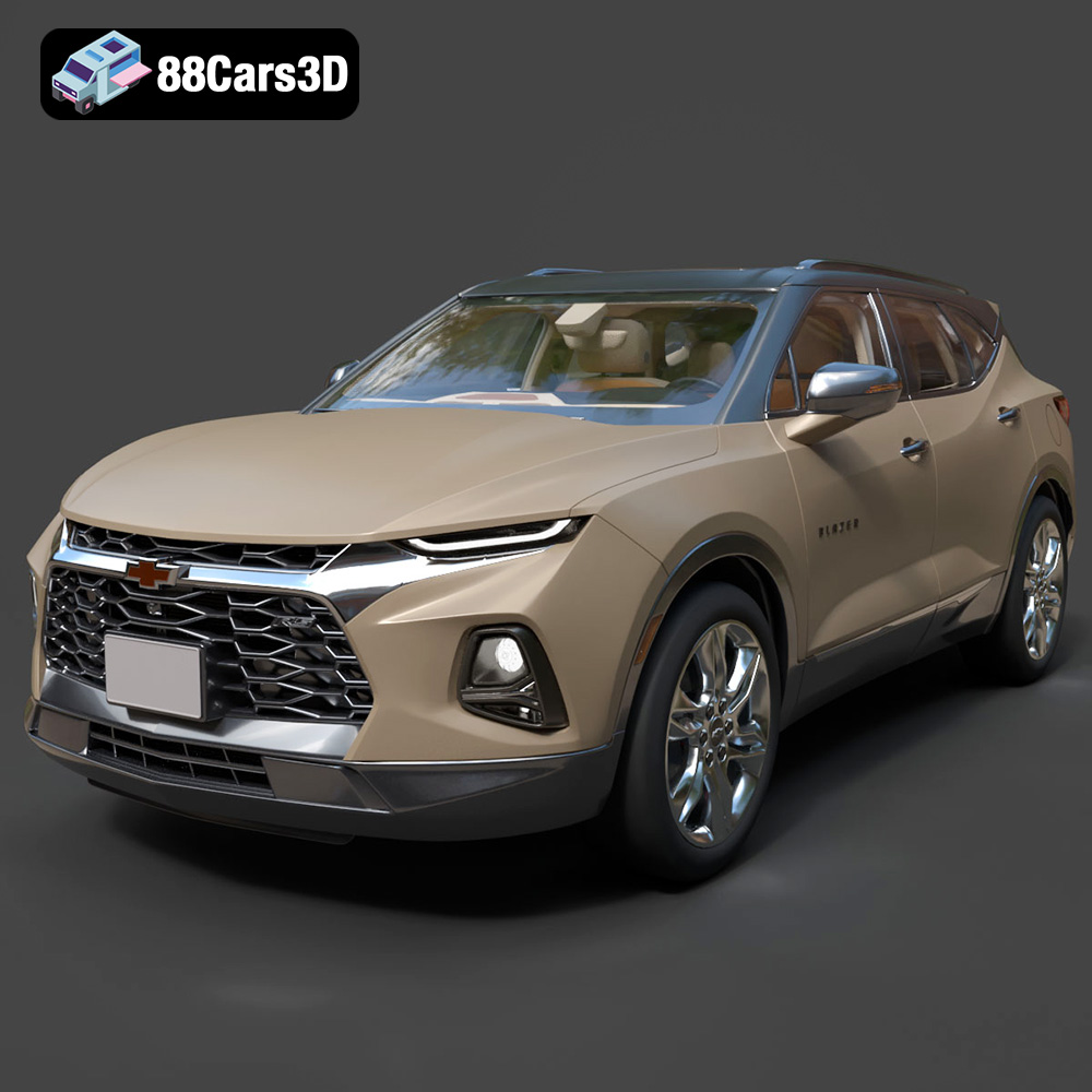
Texture: Yes | Material: Yes
Download the highly detailed, game-ready Chevrolet Blazer RS 2019 3D Model. Features bold blacked-out RS trim styling, sharp LED lighting signatures, and detailed interior geometry. Includes .blend, .fbx, .obj, .glb, .stl, .ply, .unreal, and .max formats for game development, AR/VR, and rendering.
Price: $132.50
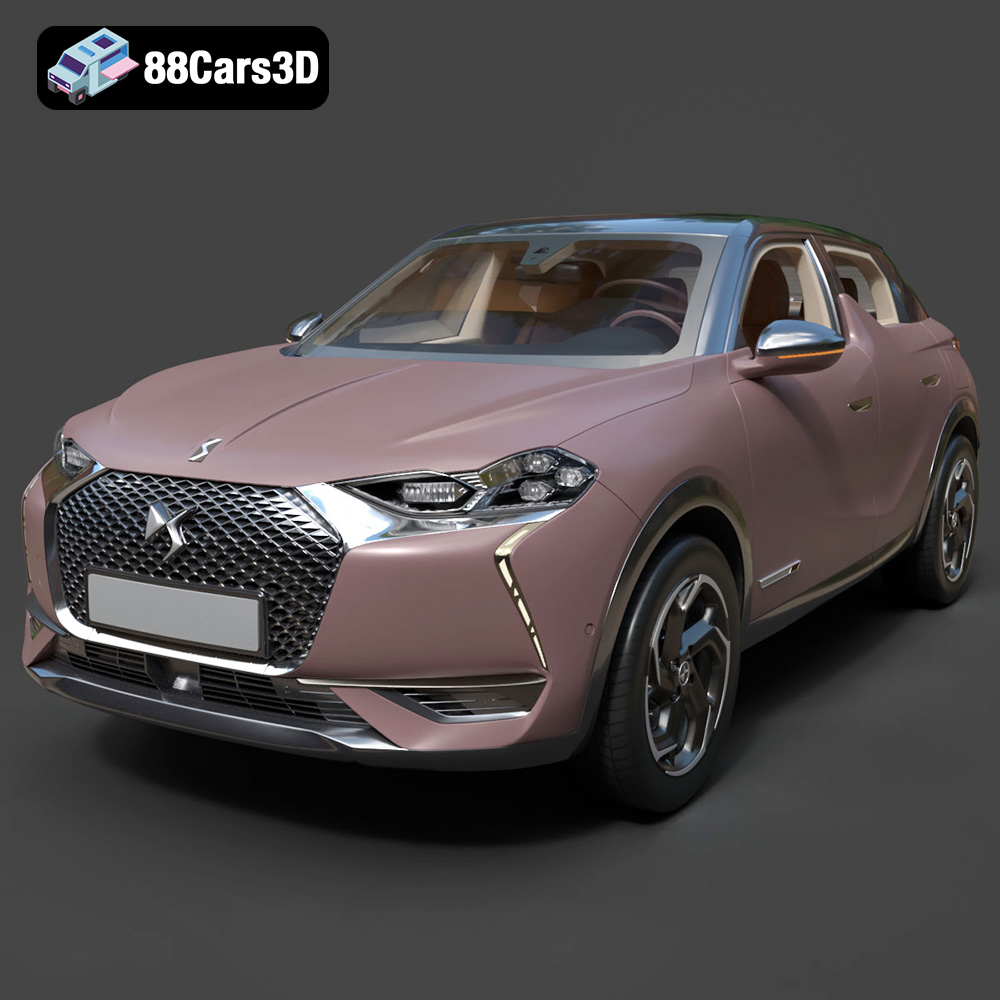
Texture: Yes | Material: Yes
Download the highly detailed, game-ready Citroen DS3 Crossback 2018 3D Model. Features signature diamond grid grille, flush door handles, and distinctive shark-fin B-pillars. Includes .blend, .fbx, .obj, .glb, .stl, .ply, .unreal, and .max formats for game development, AR/VR, and rendering.
Price: $276.00
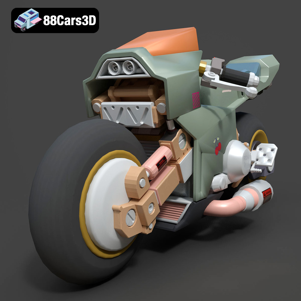
Texture: Yes | Material: Yes
Download the highly detailed, game-ready Cyber Bike 02 3D Model. Features futuristic sci-fi aesthetic, glowing LED lighting elements, and sleek aerodynamic paneling. Includes .blend, .fbx, .obj, .glb, .stl, .ply, .unreal, and .max formats for game development, AR/VR, and rendering.
Price: $99.99
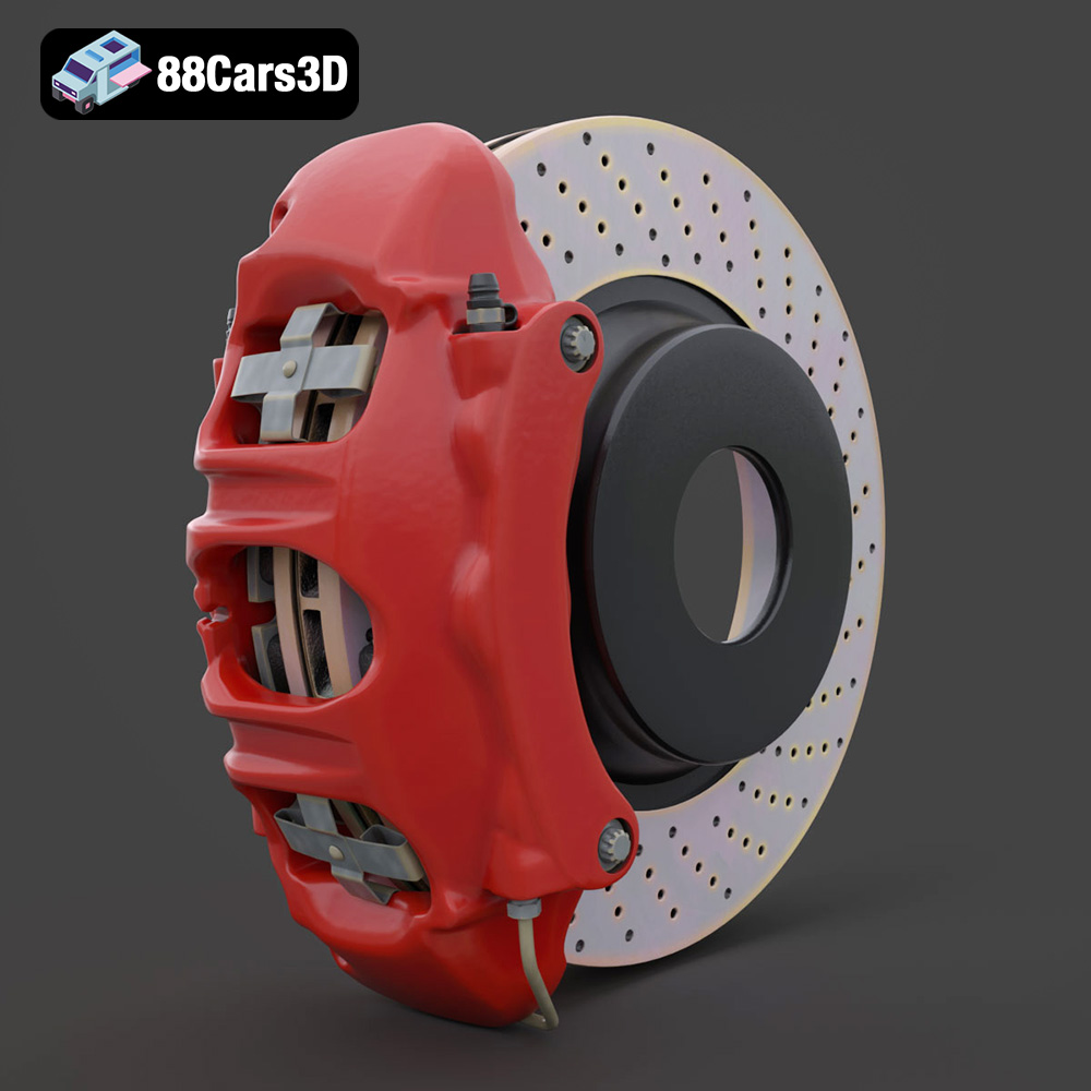
Texture: Yes | Material: Yes
Download the highly detailed, game-ready Brake Assembly 3D Model. Features a ventilated brake rotor, multi-piston caliper, and precision mounting hardware. Includes .blend, .fbx, .obj, .glb, .stl, .ply, .unreal, and .max formats for game development, AR/VR, and rendering.
Price: $104.99
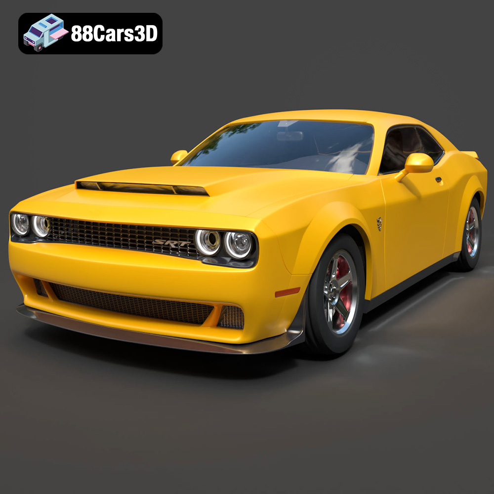
Texture: Yes | Material: Yes
Download the highly detailed, game-ready Dodge Demon SRT 3D Model. Features aggressive widebody styling, supercharged HEMI V8 details, and high-fidelity exterior details. Includes .blend, .fbx, .obj, .glb, .stl, .ply, .unreal, and .max formats for game development, AR/VR, and rendering.
Price: $279.99
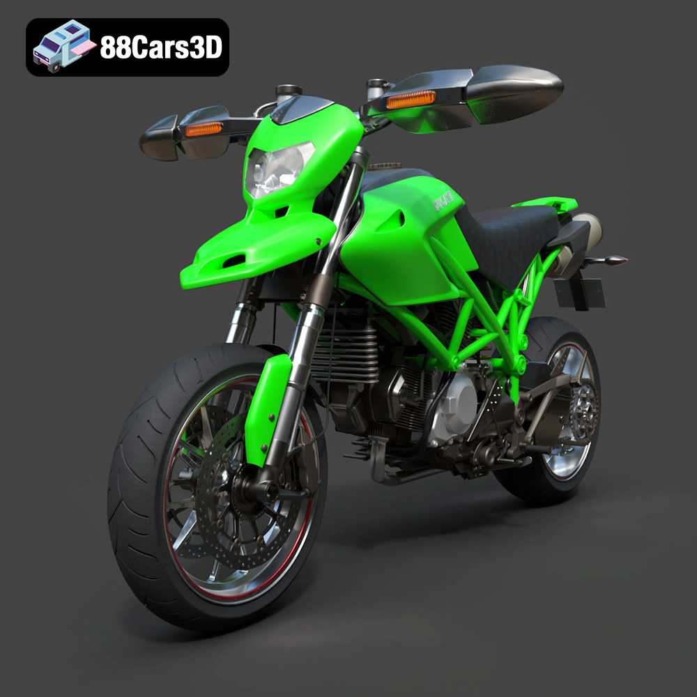
Texture: Yes | Material: Yes
Download the highly detailed, game-ready Ducati Hypermotard 1100 EVO 2011 3D Model. Features an iconic Desmodromic L-twin engine, trellis frame, and signature under-seat exhaust design. Includes .blend, .fbx, .obj, .glb, .stl, .ply, .unreal, and .max formats for game development, AR/VR, and rendering.
Price: $197.99
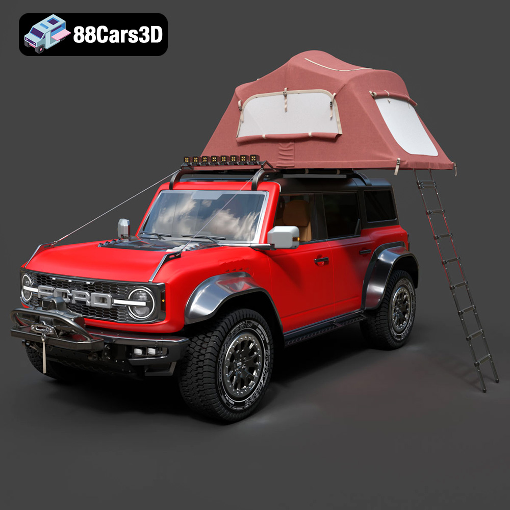
Texture: Yes | Material: Yes
Download the highly detailed, game-ready Ford Bronco Raptor Rooftop Tent 3D Model. Features aggressive widebody styling, detailed off-road suspension, and a fully modelled overland rooftop tent. Includes .blend, .fbx, .obj, .glb, .stl, .ply, .unreal, and .max formats for game development, AR/VR, and rendering.
Price: $299.50
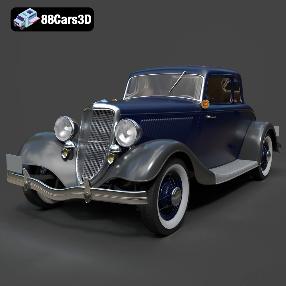
Texture: Yes | Material: Yes
Download the highly detailed, game-ready Ford Coupe 1934 3D Model. Features sweeping fenders, iconic 1930s grille design, and authentic vintage proportions. Includes .blend, .fbx, .obj, .glb, .stl, .ply, .unreal, and .max formats for game development, AR/VR, and rendering.
Price: $203.00
