
In modern automotive visualization and real-time game development, high-fidelity 3D car models are only as convincing as their motion. Static mesh displays are no longer sufficient for immersive product configurators, virtual production environments, AAA racing titles, or interactive architectural visualizations. To bridge the gap between static geometry and realistic mechanical behavior, Unreal Engine relies on a powerful engine subsystem: Animation Blueprints.
An Animation Blueprint (AnimBP) is a specialized visual script that controls the pose, mechanical deformation, and movement behaviors of a Skeletal Mesh. Whether you are driving realistic suspension travel over rough terrain, articulating active aerodynamic spoilers based on vehicle velocity, or precisely syncing steering wheel rotations with dynamic driver hands, mastering Animation Blueprints is indispensable. In this comprehensive guide, we will explore the foundational concepts, technical architectures, procedural workflows, and performance optimization strategies required to build industry-grade automotive animations in Unreal Engine.
At its core, an Animation Blueprint in Unreal Engine is a dual-graph container that combines data evaluation with pose evaluation. Unlike standard Actor Blueprints that process general gameplay logic, an Animation Blueprint is natively linked to a specific Skeleton asset and operates on frame-by-frame skeletal mesh transformations.
Every Animation Blueprint consists of two primary operational environments: the Event Graph and the Anim Graph (Animation Graph).
Blueprint Update Animation) to gather external variables—such as vehicle speed, engine RPM, steering angle, terrain contact forces, and driver inputs—from the vehicle’s Pawn or Movement Component.Output Pose node.Maintaining a strict separation of concerns between these two graphs is fundamental. The Event Graph should exclusively gather and normalize data, while the Anim Graph should purely consume that data to evaluate poses.
An automotive rig differs significantly from a standard bipedal human rig. Vehicles require rigid skeletal hierarchies where individual bones represent mechanical parts: wheels, brake calipers, suspension arms, steering columns, doors, pedals, and gauge needles. A typical production-ready vehicle skeleton adheres to a structured parent-child hierarchy:
Root (Origin at 0,0,0 on ground plane)
Chassis_Bone (Car body center of mass)
Wheel_FL / Wheel_FR / Wheel_RL / Wheel_RRCaliper_FL / Caliper_FRSteering_Wheel_BoneDoor_FL_Bone / Door_FR_BoneSpoiler_Main_Bone -> Spoiler_Flap_BoneProper bone alignment is critical. Bone axes must be standardized—typically with the X-axis representing forward motion, the Y-axis representing lateral movement, and the Z-axis representing vertical travel—to prevent axis-flipping artifacts during rotational updates in the Anim Graph.
Creating dynamic vehicle experiences begins with clean geometry and logical bone hierarchies. When sourcing high-fidelity assets from platforms like 88cars3d.com, technical artists receive 3D car models engineered specifically for real-time visualization pipelines. Pre-structured skeletal hierarchies, standardized pivot points, and clean geometry significantly streamline the process of binding an Animation Blueprint to a dynamic vehicle asset.
To animate automotive components dynamic to driving conditions, the Animation Blueprint must continuously read data from the underlying vehicle physics model, such as Unreal Engine’s Chaos Vehicle System.
The standard pattern for populating variables inside the Event Graph involves getting a reference to the owning Pawn during initialization using the Try Get Pawn Owner node. Once validated on the Blueprint Initialize Animation event, the reference is cached locally to avoid expensive runtime casting.
During the Blueprint Update Animation tick, the Event Graph queries the cached Pawn reference or its attached ChaosVehicleMovementComponent to retrieve key parameters:
Get Forward Speed (converted from cm/s to km/h or mph).Unreal Engine utilizes a multi-threaded animation evaluation pipeline. Executing standard Blueprint logic inside the Event Graph forces animation evaluation back onto the Game Thread, creating CPU bottlenecks when rendering multiple high-detail vehicles simultaneously.
To maintain maximum performance, developers should implement Thread-Safe Animation Updates. By utilizing Unreal Engine’s Property Access system inside the Anim Graph, nodes can read values directly from the vehicle blueprint without needing explicit execution nodes in the Event Graph. This unlocks the engine’s Fast Path execution, allowing pose evaluation to run entirely on worker threads parallel to the main game thread.
Raw physics inputs rarely map directly to animation channels. For smooth visual response, values must be normalized and interpolated within the Event Graph:
[-1.0, 1.0] to a physical steering wheel bone rotation range of [-450.0°, 450.0°].The Anim Graph converts data variables into skeletal poses. While skeletal control nodes handle raw mathematical bone transforms, discrete mechanical behaviors and continuous variable-driven movements are best handled using State Machines and Blend Spaces.
State Machines organize complex animation behaviors into distinct operational states linked by logical transitions. In automotive visualization, State Machines excel at managing discrete mechanical assemblies such as convertible soft-tops, active rear aerodynamic spoilers, scissor doors, or motorized headlight covers.
Consider an active aerodynamic rear wing system with three states:
Vehicle Speed > 80 km/h. The wing raises vertically and tilts to a low-drag angle.Brake Input > 0.5 AND Vehicle Speed > 120 km/h. The wing tilts aggressively forward (70°) to simulate aerodynamic drag assistance.Crossfade transitions between these states ensure smooth positional blending, eliminating harsh pops in geometry during high-speed driving sequences.
A Blend Space maps one or two input parameters across a multi-dimensional grid to smoothly interpolate between multiple pose samples. In vehicle cockpits, a 2D Blend Space (mapping Steering Angle on the X-axis and Vehicle G-Force/Acceleration on the Y-axis) allows driver character models to shift their weight, turn the wheel, and lean into high-speed corners dynamically.
For standalone vehicle meshes, a 1D Blend Space can continuously drive steering assembly geometry, brake pedal displacement, and paddle shifter movements with sub-frame accuracy.
Automotive animation often requires isolating dynamic movements to specific skeletal branches. The Layered blend per bone node allows you to combine multiple pose streams based on skeleton filter masks.
For example, a dynamic chassis sway/body-roll pose stream generated by dynamic g-forces can be blended with a procedural suspension travel pose stream. By specifying Chassis_Bone as the branch filter, body roll affects only the upper bodywork, leaving the lower wheel assemblies to process physical terrain collision independently.
Manual keyframe animation cannot anticipate dynamic in-game physics terrain, unexpected surface bumps, or procedural steering adjustments. To achieve realistic realism, developers employ dynamic, procedural node graphs inside the Anim Graph.
In modern high-detail 3D car models, steerable front wheel hubs are physically attached to mechanical tie rods, rack-and-pinion assemblies, and steering linkages. Manually animating these secondary linkages is inefficient. Instead, developers leverage the Look At skeletal control node.
By attaching a Look At node to the tie-rod bone and setting its target to the steering knuckle bone joint, the tie rod automatically rotates to point toward the turning wheel assembly in real time, maintaining perfect mechanical alignment regardless of wheel angle or vertical suspension travel.
Unreal Engine provides a dedicated Wheel IK node designed to work alongside the Chaos Vehicle physics system. The Wheel IK node automatically reads the dynamic wheel offsets calculated by the physics solver and applies corresponding spatial translations and rotations to the target skeletal bones.
When configured correctly, the Wheel IK node handles:
Beyond suspension, secondary powertrain components demand real-time motion. Driveshafts and exposed differential axles must rotate in direct proportion to wheel velocity. Using the Transform (Modify) Bone node in Local Space, developers can multiply calculated wheel rotation speeds by gear ratios to continuously rotate shaft bones along their longitudinal axis, adding technical depth to undercarriage shots during cinematics.
As rendering quality approaches photorealism in real-time pipelines, static geometry transforms are no longer enough. Advanced animation workflows integrate Control Rig, Anim Curves, and Morph Targets into the Animation Blueprint workflow.
Control Rig is Unreal Engine’s scriptable rigging system that enables procedural IK and complex mathematical constraints directly on skeletal meshes. Rather than baking heavy keyframe data in external CAD or 3D modeling software, technical artists construct procedural Control Rigs for intricate mechanics like multi-link suspension linkages, scissor doors, or convertible top scissor arms.
Using the Control Rig node directly inside an Animation Blueprint’s Anim Graph allows values from the Event Graph to feed into Control Rig parameters, yielding real-time mechanical inverse kinematics with zero latency. To learn more about standard Unreal Engine animation tools and Control Rig integration, consult the official Unreal Engine Learning Hub.
Modern vehicles feature digital instrument clusters and dynamic needle gauges. Animation Blueprints facilitate dashboard visualization by utilizing Animation Curves and dynamic material parameter bindings:
Transform (Modify) Bone node rotates needle bones based on normalized engine RPM or speed curves.Rigid skeletal meshes cannot easily simulate soft rubber contact patch flattening when a vehicle lands hard from a jump or corners aggressively. By embedding Morph Targets (blend shapes) into the vehicle’s tire meshes, technical artists can deform tire walls under load.
Inside the Anim Graph, the Modify Curve or Set Morph Target node reads vertical suspension compression forces from the physics solver and drives morph target weights from 0.0 (unloaded, perfectly round tire) to 1.0 (loaded, flattened tire contact patch with bulging sidewalls), significantly enhancing photorealism.
Complex vehicle setups featuring hundreds of moving skeletal parts, dynamic IK solvers, and multi-layered blend trees can quickly degrade CPU performance—especially when rendering dense traffic scenes or complex multiplayer grids. Optimizing Animation Blueprints is vital for maintaining target framerates (60+ FPS) in real-time applications.
The single most impactful optimization for Animation Blueprints is ensuring your Anim Graph operates completely on the Fast Path. When Fast Path execution is active, Unreal Engine displays small light-blue lightning bolt icons on the upper-right corner of Anim Graph nodes.
To prevent Fast Path breaking:
When multiple animated vehicles exist within a scene (such as AI traffic or distant racing opponents), updating every skeleton every frame is wasteful. Unreal Engine provides two key built-in scaling utilities:
Over-rigging is a common technical pitfall. Adding dedicated skeletal bones for microscopic details (such as interior switches or tiny engine bolts) inflates bone matrix transformation costs exponentially across active scenes.
When sourcing 3D assets for commercial projects, selecting clean, professionally rigged assets is critical. High-grade vehicles, such as the 3D car models available at 88cars3d.com, feature optimized skeletal structures engineered specifically for real-time engines. Proper bone parenting, streamlined skeletal hierarchies, and pre-configured LOD (Level of Detail) setups ensure optimal performance without sacrificing visual detail or mechanical accuracy.
| Feature Area | Recommended Practice | Performance Impact |
|---|---|---|
| Graph Execution | Utilize Property Access to enforce Fast Path parallel evaluation on worker threads. | High: Reduces Game Thread CPU execution bottlenecks. |
| Mechanical Rigging | Implement procedural IK (Look At / Control Rig) for suspension and steering linkages instead of baked keyframes. | Medium: Guarantees accurate physical contact while keeping asset file sizes small. |
| Cockpits & UI | Combine 1D Blend Spaces with Dynamic Material Parameters for analog and digital dashboards. | Low: Delivers smooth gauge movement with minimal performance overhead. |
| Multi-Vehicle Scenes | Configure Update Rate Optimization (URO) and Animation Budget Allocator for background assets. | High: Enables rendering dense traffic scenes and large race grids at locked framerates. |
| Asset Selection | Use well-structured skeletal meshes with standardized bone hierarchies and optimized bone counts. | High: Eliminates rigging overhead and ensures smooth asset integration into Unreal Engine. |
Mastering Animation Blueprints in Unreal Engine transforms static 3D car models into responsive, interactive vehicles. By understanding the division between the Event Graph and Anim Graph, taking advantage of state machines and procedural IK nodes, incorporating Control Rig for complex mechanics, and adhering to multi-threaded Fast Path optimization practices, technical artists can achieve stunning real-time realism across automotive configurators, virtual production, and high-performance games.
Whether you are building a dynamic racing title or a high-end visualization demo, pairing robust Animation Blueprints with professionally built assets—such as the optimized automotive models from 88cars3d.com—ensures your real-time projects deliver unmatched visual fidelity and computational efficiency.
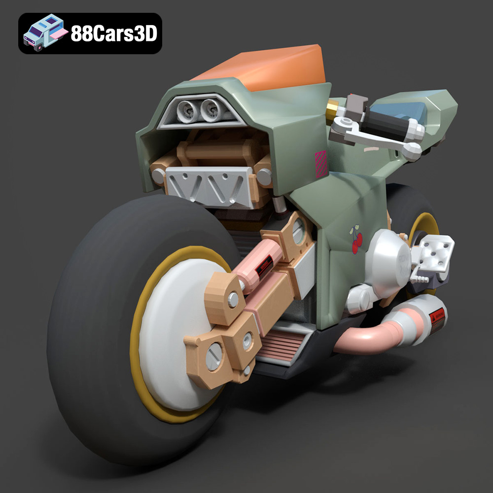
Texture: Yes | Material: Yes
Download the highly detailed, game-ready Cyber Bike 02 3D Model. Features futuristic sci-fi aesthetic, glowing LED lighting elements, and sleek aerodynamic paneling. Includes .blend, .fbx, .obj, .glb, .stl, .ply, .unreal, and .max formats for game development, AR/VR, and rendering.
Price: $40
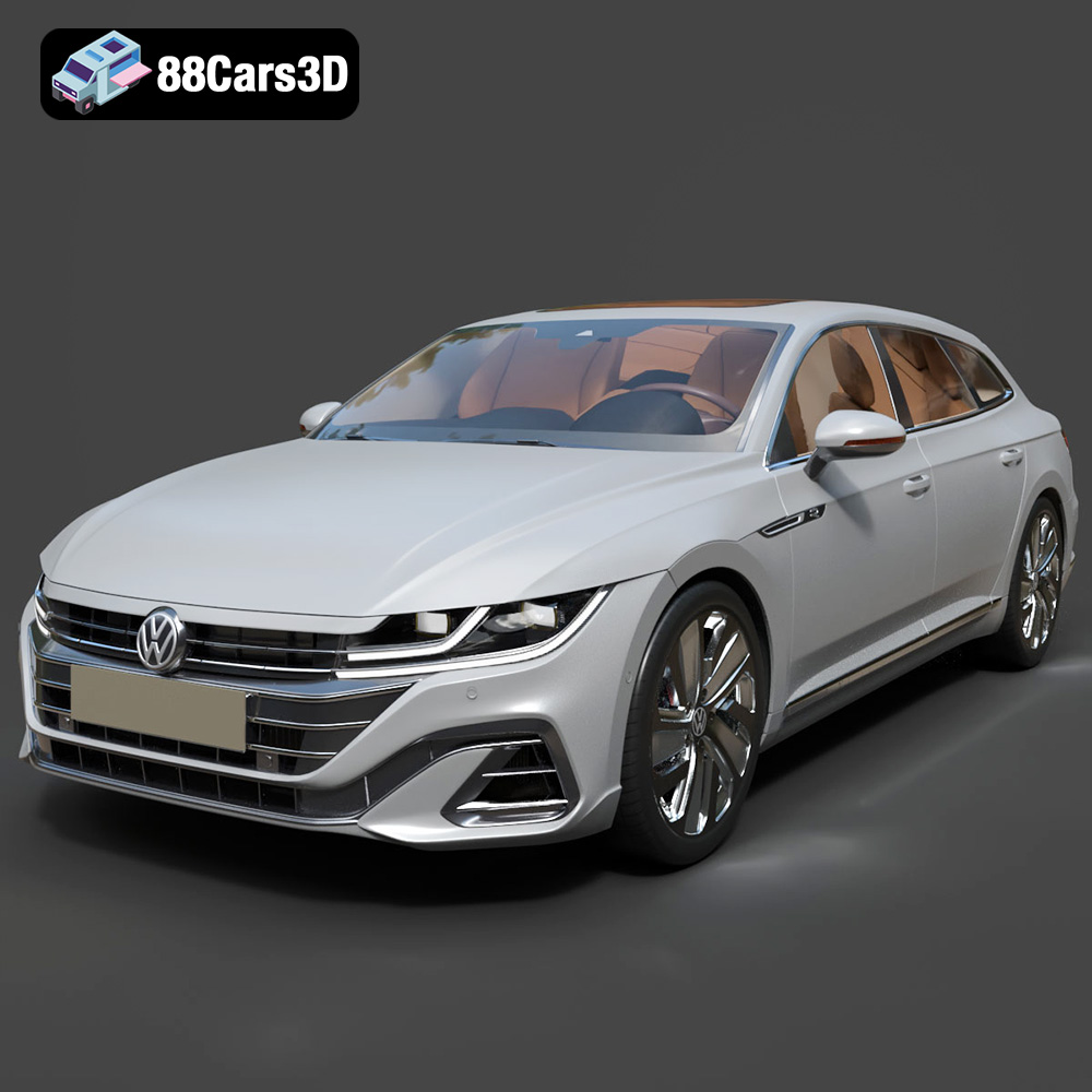
Texture: Yes | Material: Yes
Download the highly detailed, game-ready Volkswagen Arteon Shooting Brake Hybrid 2021 3D Model. Features sleek shooting brake silhouette, illuminated dynamic front grille, and full digital cockpit interior. Includes .blend, .fbx, .obj, .glb, .stl, .ply, .unreal, and .max formats for game development, AR/VR, and rendering.
Price: $40
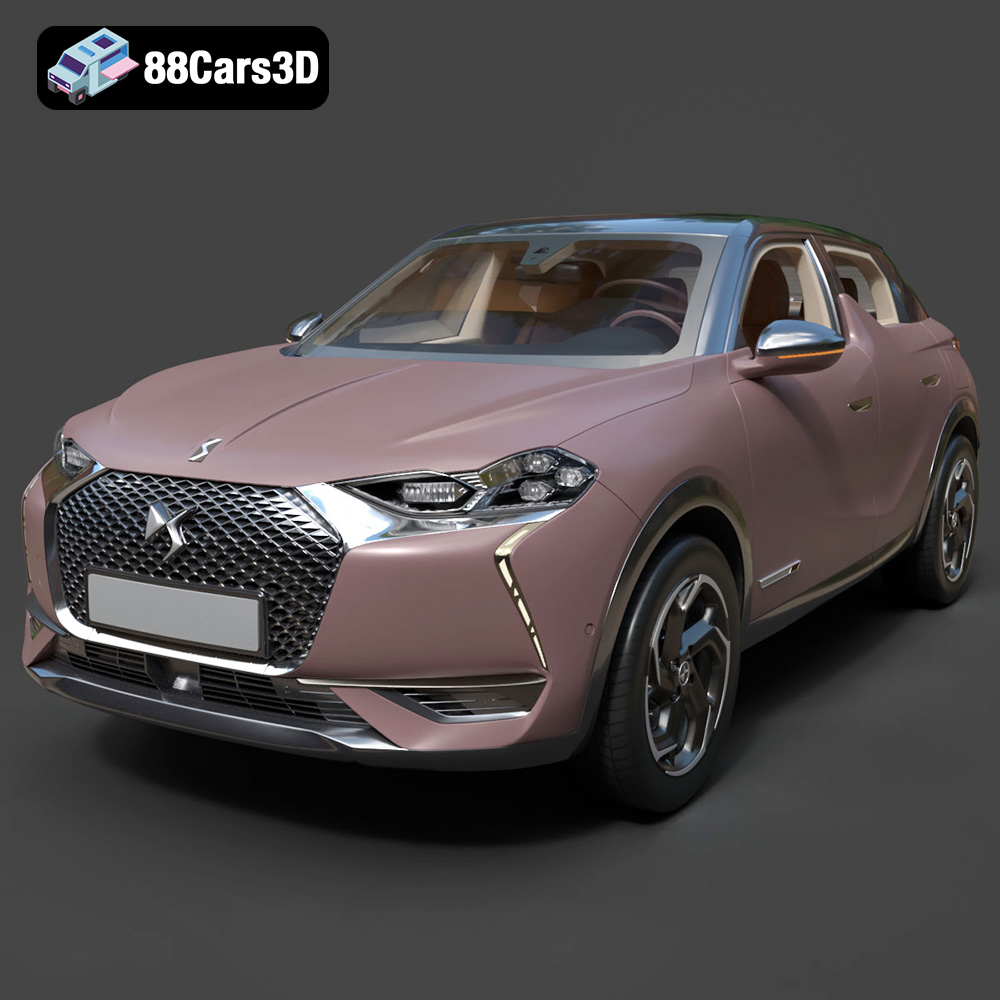
Texture: Yes | Material: Yes
Download the highly detailed, game-ready Citroen DS3 Crossback 2018 3D Model. Features signature diamond grid grille, flush door handles, and distinctive shark-fin B-pillars. Includes .blend, .fbx, .obj, .glb, .stl, .ply, .unreal, and .max formats for game development, AR/VR, and rendering.
Price: $40
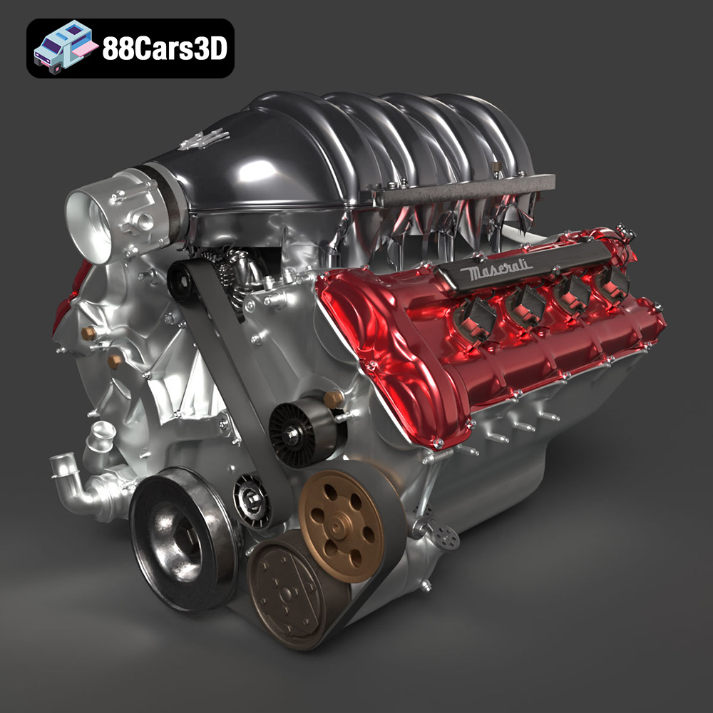
Texture: Yes | Material: Yes
Download the highly detailed, game-ready Maserati Engine 3D Model. Features intricate cylinder heads, realistic intake manifold, and precision mechanical detailing. Includes .blend, .fbx, .obj, .glb, .stl, .ply, .unreal, and .max formats for game development, AR/VR, and rendering.
Price: $40
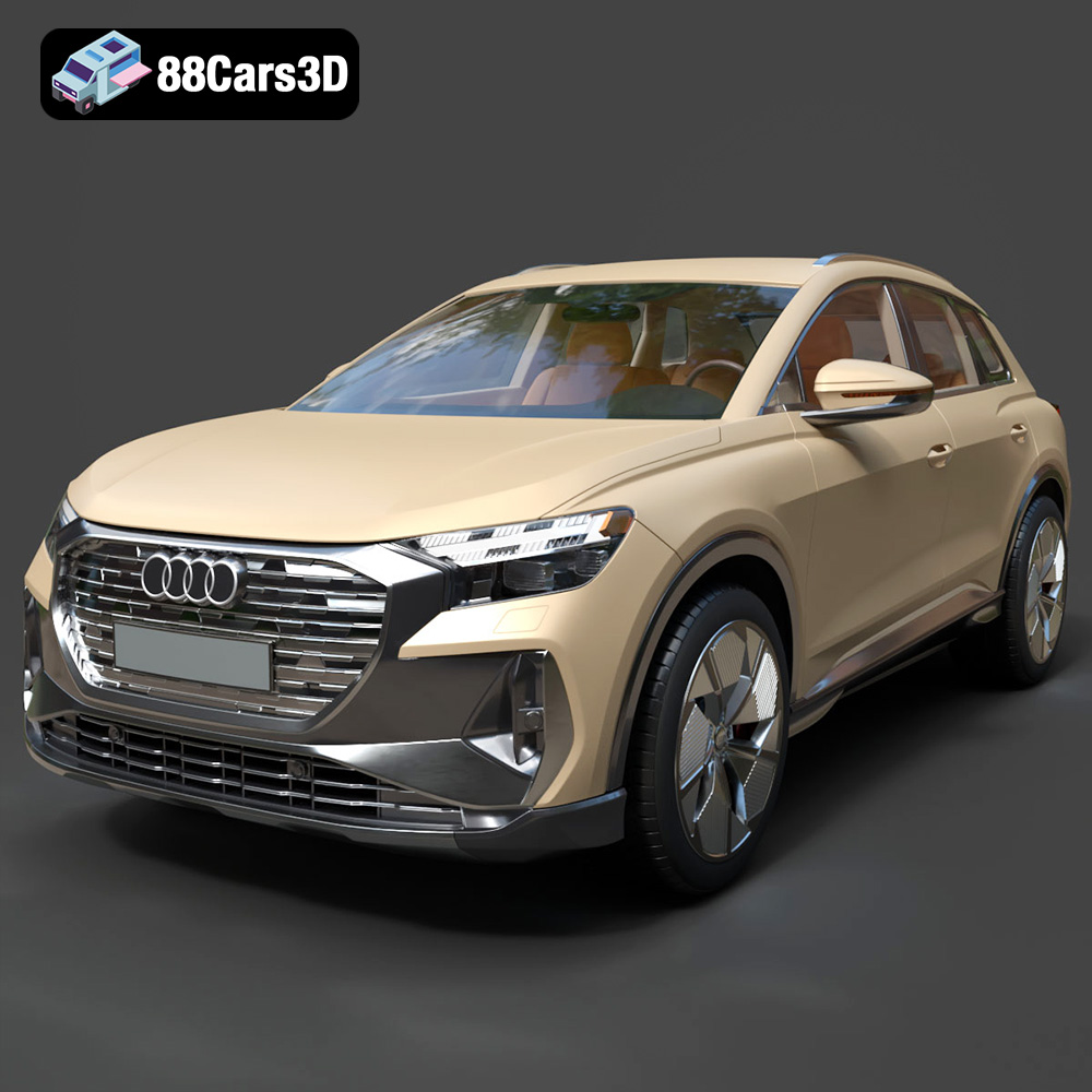
Texture: Yes | Material: Yes
Download the highly detailed, game-ready Audi Q4 e-tron 2021 3D Model. Features sleek electric SUV styling, signature Singleframe grille, and detailed Matrix LED lighting. Includes .blend, .fbx, .obj, .glb, .stl, .ply, .unreal, and .max formats for game development, AR/VR, and rendering.
Price: $40
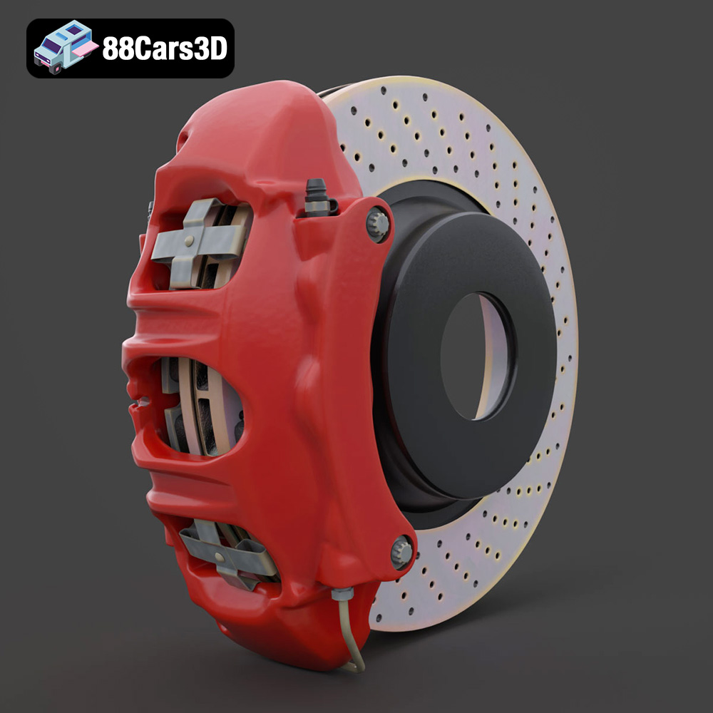
Texture: Yes | Material: Yes
Download the highly detailed, game-ready Brake Assembly 3D Model. Features a ventilated brake rotor, multi-piston caliper, and precision mounting hardware. Includes .blend, .fbx, .obj, .glb, .stl, .ply, .unreal, and .max formats for game development, AR/VR, and rendering.
Price: $40
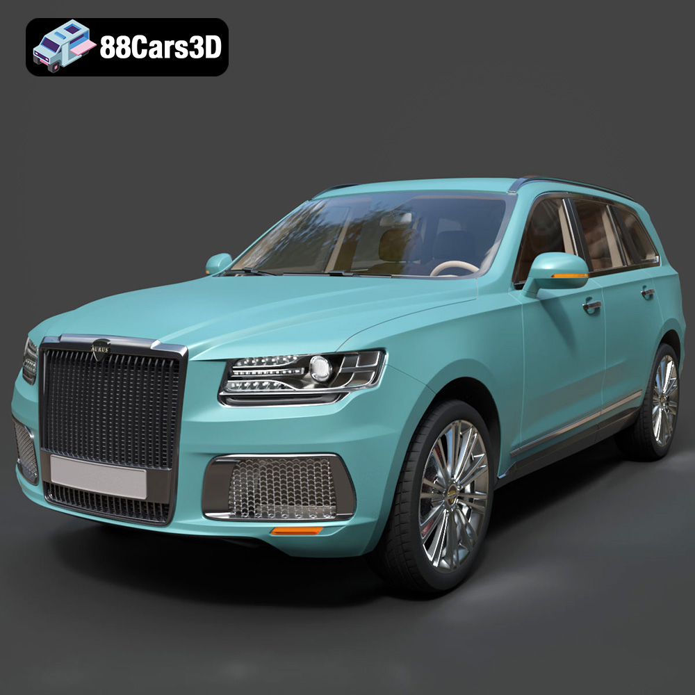
Texture: Yes | Material: Yes
Download the highly detailed, game-ready Aurus Komendant 2020 3D Model. Features an imposing front grille, executive full-size SUV silhouette, and detailed luxury interior. Includes .blend, .fbx, .obj, .glb, .stl, .ply, .unreal, and .max formats for game development, AR/VR, and rendering.
Price: $40
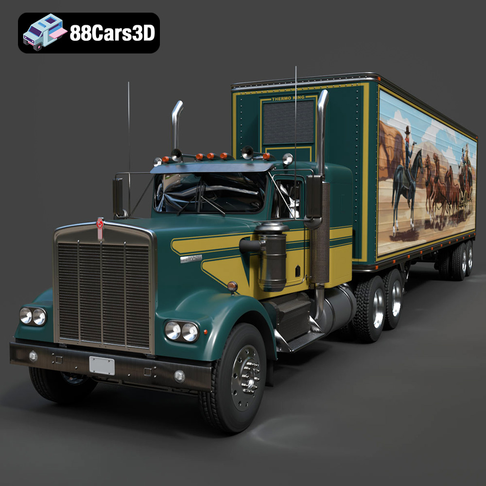
Texture: Yes | Material: Yes
Download the highly detailed, game-ready Kenworth W900 1974 3D Model. Features classic long-nose hood styling, detailed chrome exhaust stacks, and realistic dual tandem axles. Includes .blend, .fbx, .obj, .glb, .stl, .ply, .unreal, and .max formats for game development, AR/VR, and rendering.
Price: $40
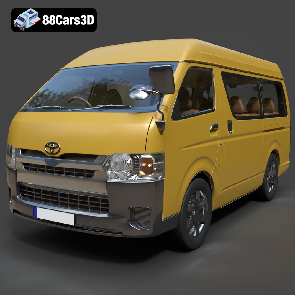
Texture: Yes | Material: Yes
Download the highly detailed, game-ready Toyota Hiace Passenger Van L1H3 DX 2013 3D Model. Features authentic high-roof van body proportions, detailed interior seating layout, and realistic exterior lighting. Includes .blend, .fbx, .obj, .glb, .stl, .ply, .unreal, and .max formats for game development, AR/VR, and rendering.
Price: $208.99
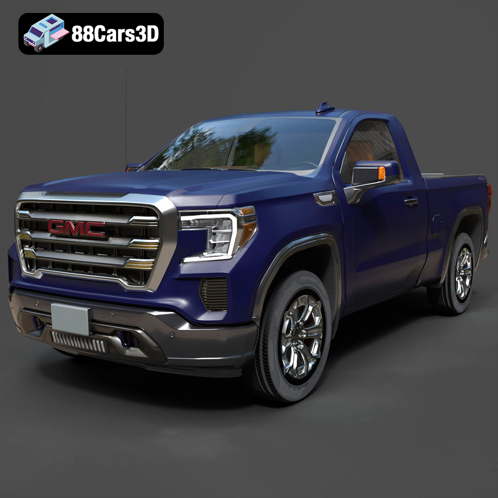
Texture: Yes | Material: Yes
Download the highly detailed, game-ready GMC Sierra Reg SLE 1500 2020 3D Model. Features bold pickup styling, detailed exterior trim, accurate undercarriage, and realistic cabin. Includes .blend, .fbx, .obj, .glb, .stl, .ply, .unreal, and .max formats for game development, AR/VR, and rendering.
Price: $40
