Get 50% OFF All Premium 3D & STL Models!
“`html
The world of 3D printing, particularly when it comes to detailed replicas like automotive models, hinges on a fundamental understanding of file formats. Among these, the STL (STereoLithography) format reigns supreme, forming the backbone of countless successful prints. Whether you’re a seasoned maker creating intricate model car bodies or a beginner assembling your first printable classic, grasping the nuances of STL files is paramount. This article will demystify the STL format, explore its inherent strengths and weaknesses, and guide you through the essential steps of preparing and printing STL files for stunning results. We’ll dive deep into slicing strategies, support generation, print orientation, and the crucial role of file integrity, ensuring your journey from digital model to tangible masterpiece is as smooth and successful as possible. Get ready to elevate your 3D printing game and bring your favorite vehicles to life with unparalleled precision.
The StereoLithography (STL) file format, developed by 3D Systems in the late 1980s, has become the de facto standard for transmitting 3D models to 3D printers. Its simplicity and widespread adoption are key to its enduring popularity. At its core, an STL file describes the surface geometry of a 3D object using a collection of connected triangles. Each triangle is defined by the coordinates of its three vertices and a normal vector, which indicates the outward-facing direction of the surface. This seemingly basic representation is incredibly effective for 3D printers, which essentially work by slicing the model into thin layers and building them up. The tessellated nature of STL makes it inherently compatible with this layered manufacturing process.
The primary reason for STL’s dominance lies in its sheer universality. Nearly all 3D modeling software, from professional CAD packages to free sculpting tools, can export to STL. Crucially, every 3D printer slicer software—the programs that translate 3D models into machine instructions—is designed to read and process STL files. This broad compatibility means that whether you download a meticulously crafted printable car model from platforms like 88cars3d.com or design your own, the STL format ensures it can be imported into your preferred slicing software and sent to your printer with minimal fuss. While other formats like OBJ, FBX, and 3MF exist and offer advantages like color and texture information, STL’s focus on pure geometry makes it the most reliable choice for the fundamental task of printing.
Delving deeper, an STL file can be in one of two formats: ASCII or binary. ASCII STL files are human-readable and text-based, making them easier to inspect and edit manually, though they can be significantly larger in file size. Binary STL files, conversely, are more compact and efficient, consisting of raw binary data. Regardless of the encoding, the fundamental data structure remains the same: a list of triangular facets. Each facet comprises three vertices (X, Y, Z coordinates) and a normal vector (also X, Y, Z). The normal vector is critical as it defines the orientation of the triangle’s surface, ensuring that the slicer software understands which side is “outside” the model. A consistently oriented set of normals is crucial for a watertight, printable model.
Despite its strengths, STL is a surface-only representation. It does not store information about color, material properties, texture, or internal structures like infill. This means that features like complex internal lattices or specific material assignments must be handled entirely by the slicing software. Furthermore, STL files are prone to errors like holes, inverted normals, and self-intersecting geometry, often referred to as “non-manifold” geometry. These issues can cause significant problems during slicing and printing, necessitating careful file repair before a successful print can be achieved. Understanding these limitations is the first step towards overcoming them.
Once you have your STL file, the next critical stage is using slicing software. Slicers like Ultimaker Cura, PrusaSlicer, or Simplify3D act as the bridge between your 3D model and your 3D printer. They take the geometric data from the STL file and generate a series of layered toolpaths—instructions that your printer’s extruder or laser follows to build the object layer by layer. The settings you choose within your slicer have a profound impact on the final print quality, strength, and print time. This is where the art and science of 3D printing truly converge, and for detailed models, fine-tuning these parameters is essential.
Key slicing parameters revolve around layer height, print speed, infill, and support structures. Layer height directly influences the vertical resolution of your print. A smaller layer height (e.g., 0.1mm) will result in a smoother finish with less visible layer lines, ideal for detailed car models, but significantly increases print time. Conversely, a larger layer height (e.g., 0.2mm or 0.3mm) prints much faster but results in a more pronounced stepped appearance. Print speed affects both speed and quality; faster speeds can lead to artifacts like ringing or poor layer adhesion if not calibrated correctly. Infill determines the internal structure of the print, affecting its strength, weight, and material consumption. Support structures are generated automatically or manually to hold up overhangs and bridges that would otherwise collapse during printing.
When working with high-quality STL files from sources like 88cars3d.com, the models are typically designed with printing in mind, often including pre-supported versions or optimized geometry. However, understanding your slicer allows you to further refine these settings. For instance, you might choose a different infill pattern (e.g., gyroid for strength and flexibility, or cubic for good balance) and density (e.g., 15-25% for most decorative models, higher for functional parts) based on the specific requirements of your car model project. Experimentation and careful observation of test prints are crucial for dialing in the perfect settings for your specific printer and material combination.
The layer height setting is perhaps the most direct influence on both print quality and duration. For highly detailed automotive models where smooth curves and fine details are paramount, a layer height of 0.1mm or even 0.08mm might be chosen. This can drastically increase print times, with a small 1:24 scale car model potentially taking 20-40 hours to print. On the other hand, if speed is a priority or the model is for a less critical application, a 0.2mm or 0.3mm layer height can reduce print times by half or more, making the model more accessible for rapid prototyping or less demanding hobbyist projects. Always consider the balance between desired aesthetic and acceptable turnaround time.
The internal structure of your 3D print is controlled by infill settings. Infill density, usually expressed as a percentage, determines how much material fills the interior of the model. For most display models, 15-25% infill is sufficient to provide structural integrity without excessive material use or weight. For parts requiring higher strength, such as functional components or larger models, densities of 40-80% might be necessary. Beyond density, the infill pattern also plays a role. Common patterns include Grid, Lines, Cubic, Gyroid, and Honeycomb. Gyroid is often favored for its strength in all directions and good bridging capabilities, while Cubic offers a robust structure. Choosing the right infill pattern and density optimizes the balance between mechanical properties, print time, and material cost.
3D printing inherently struggles with overhangs and bridges—features that extend horizontally over empty space. Without proper support, these areas will droop, sag, or fail entirely. Support structures are temporary geometries printed alongside the main model that provide a scaffold for these challenging features. Generating effective supports is a critical skill, especially when printing complex objects like intricate car models with spoilers, wheel wells, and undercarriage details. The goal is to create supports that are strong enough to hold the model but also easy to remove without damaging the final print.
Modern slicers offer sophisticated support generation tools. You can often choose between different support types, such as standard (tree-like) supports or more direct “normal” supports. Tree supports, often called “tree” or “organic” supports in some slicers, branch out and touch the model only at critical points, using less material and being easier to remove in many cases. The density, pattern, and interface settings for supports are also configurable. A finer interface layer between the support and the model can lead to a smoother surface finish where supports were attached. Furthermore, supports can be enabled for all overhangs or only those exceeding a specific angle threshold (e.g., 45 degrees). Identifying and supporting critical overhangs is key, and for printable car models, this often includes areas like the underside of fenders, the roof, and any protruding aerodynamic elements.
Some advanced users may opt for manual support placement or use dedicated mesh editing software to add custom supports. For enthusiasts downloading models from marketplaces like 88cars3d.com, it’s common to find models offered in both pre-supported and unsupported versions. The unsupported versions give you maximum control over support placement, allowing you to tailor them to your specific printer and chosen orientation, while pre-supported versions offer a convenient starting point.
Tree supports are a popular choice for their efficiency and ease of removal. They spread out like branches, contacting the model only where necessary. This minimizes contact points, reducing the amount of post-processing required. Normal or standard supports, on the other hand, form more of a solid block or grid structure beneath overhangs. While they can be very effective, they often leave more prominent marks on the model’s surface and can be more difficult to clean up. The choice between them depends on the model’s geometry, the material being used, and personal preference for support removal.
The “interface” between the support structure and the actual model is crucial for achieving a clean finish. Slicers allow you to define an interface layer or raft. This layer is typically printed at a higher density or with a different pattern than the rest of the support, creating a more solid surface for the model to adhere to. When this interface is well-tuned, it provides a clean break when supports are removed, leaving minimal scarring on the model’s surface. Fine-tuning the distance between the model and the support (Z-distance) is also critical; too small and they’ll be fused, too large and the model will sag.
The way you orient your STL model on the print bed and ensure proper bed adhesion are foundational elements for a successful print. Print orientation affects print quality, strength, and the necessity and complexity of support structures. Bed adhesion ensures that the first layer sticks firmly to the print surface, preventing the print from shifting or detaching mid-print, which is a common cause of failure. For printable car models, understanding these aspects can make the difference between a flawless replica and a discarded print.
When orienting a car model, consider how the layers will be built. Printing a car upright, for example, would require extensive supports for the entire underside, potentially leading to a rough finish in complex areas. Often, printing the car on its side, or even upside down with the roof on the build plate, can minimize the need for supports or place them in less visible areas. For FDM printing, the build orientation also impacts the anisotropic strength of the plastic; parts are generally stronger along the X and Y axes than along the Z axis (layer lines). This is important if your printed car model will undergo any stress. Bed adhesion is achieved through various methods: using a heated print bed, applying adhesives like glue stick or hairspray, using specialized build surfaces (like PEI or glass), and ensuring the first layer is printed slowly and at the correct height.
For resin printers, orientation is also critical, but for different reasons. Resin prints are cured by UV light, and the build plate moves upwards. Gravity plays a significant role, and overhangs can experience immense “peeling forces” as they are pulled from the resin bath. Thus, orienting resin prints to minimize suction and large, flat surfaces parallel to the build plate is essential, often involving angling the model at 30-45 degrees and using generous supports.
For car models, careful orientation can drastically reduce the amount of support material needed. Consider the most challenging overhangs on a specific vehicle. Can you rotate the model so that these features become flatter or less acute? For instance, a spoiler might be better supported if printed at an angle rather than directly from the build plate. Sometimes, printing a model in multiple parts and assembling them can allow for optimal orientation of each component, leading to a superior final result. Tools like Meshmixer or Blender can help you preview different orientations and visualize support needs before slicing.
A failed first layer is often the beginning of a failed print. Ensure your build surface is clean and free of dust or oils. For FDM printers, check that your bed is level and the nozzle height is correctly set (often referred to as “Z-offset”). A perfect first layer should be slightly squished into the build surface, creating a smooth, unbroken foundation. Using a brim or raft in your slicer settings can increase the surface area of the first layer, providing better adhesion, especially for models with small contact points. For resin printers, ensuring the build plate is clean and level, and the initial adhesion layers are printed slowly and with sufficient exposure time, is paramount.
Even seemingly perfect STL files can harbor hidden errors that can lead to failed prints. These “non-manifold” errors, such as holes, inverted normals, self-intersecting triangles, or disconnected parts, can confuse the slicing software, resulting in missing sections, incorrect toolpaths, or complete slicing failures. Robust file preparation and repair are therefore indispensable steps, especially when dealing with complex geometries like those found in detailed automotive models.
The process typically begins with inspecting the STL file in a mesh editing or repair software. Programs like Microsoft 3D Builder, Autodesk Meshmixer, Netfabb (now part of Fusion 360), or even Blender offer tools to diagnose and fix these issues. Common repair operations include filling holes, flipping inverted normals to ensure outward-facing consistency, and merging overlapping vertices. For printable car models, especially those downloaded from various sources, performing a quick mesh check is always a good practice. Some slicers also have built-in basic repair functions, but dedicated software often provides more comprehensive solutions. Ensuring your STL is “watertight” – meaning it forms a single, enclosed volume without any breaches – is the ultimate goal of this stage.
Beyond basic repair, you might also need to manipulate the mesh for printing. This could involve thickening thin walls that would be too fragile to print, smoothing rough surfaces, or even separating a complex model into individual printable parts. For example, a highly detailed engine bay might be best printed as a separate component and then assembled onto the car body.
Non-manifold geometry refers to any topological errors that prevent a mesh from being a “clean” solid. This includes issues like:
Software like Meshmixer can automatically detect and often fix these issues with its “Make Solid” or “Inspector” tools. A manual review after automatic repair is often recommended.
Many 3D models, particularly those created for rendering or animation, may have surfaces that are only one polygon thick. These will not print successfully on most 3D printers. Mesh editing software allows you to “offset” or “thicken” these surfaces to a printable thickness (e.g., 0.8mm to 1.5mm for FDM, depending on nozzle size). Similarly, if a model has very fine details that are prone to damage during printing or post-processing, you might use smoothing tools to slightly simplify or refine the mesh. However, caution is advised with smoothing, as it can also obliterate crucial fine details on intricate car models.
Beyond the fundamental steps, advanced techniques and careful material selection can significantly elevate the quality of your 3D printed car models. The choice of filament (for FDM) or resin (for SLA/DLP) directly impacts the aesthetic, strength, and post-processing capabilities of your prints. Furthermore, understanding advanced slicing features and post-processing methods opens up new possibilities for realism and customization.
For FDM printing, PLA is a popular choice due to its ease of printing, low warping, and wide range of available colors, making it ideal for vibrant car finishes. PETG offers greater durability and temperature resistance, useful if the model might be exposed to heat. ABS provides excellent strength and can be smoothed with acetone vapor, but it requires a heated enclosure and good ventilation due to fumes. For resin printing, standard resins offer high detail but can be brittle. Tough resins mimic ABS properties, while flexible resins can be used for tires or other components. Experimenting with different materials and their specific printing parameters (temperatures, cooling, retraction for FDM; layer exposure times for resin) is key.
Advanced slicing techniques might include using fuzzy skin settings for textured surfaces (like tires), ironing for perfectly smooth top surfaces, or precise control over retraction to minimize stringing. Post-processing is where many model cars truly come alive. This involves cleaning supports, sanding to remove layer lines and imperfections, priming, and painting. Techniques like airbrushing, weathering, and applying decals can transform a plain plastic print into a stunningly realistic scale model. For multi-part models, designing for easy assembly, perhaps with interlocking features or alignment pins, is also an advanced consideration.
PLA: Easy to print, good detail, biodegradable. Best for display models. Wide color selection. Can be brittle.
PETG: More durable and heat-resistant than PLA. Good for parts that need some flexibility or resilience. Can be stringy.
ABS: Strong, durable, high-temperature resistance. Requires a heated enclosure and good ventilation due to fumes. Can be smoothed with acetone vapor.
Resins: Standard resins offer extreme detail but are often brittle. Tough resins provide better impact resistance. Flexible resins for specific applications. Requires careful handling and post-curing.
The raw print is just the beginning.
The STL file format, despite its age and limitations, remains the undisputed champion for 3D printing due to its universal compatibility and focus on pure geometry. Mastering this format, from understanding its tessellated structure to preparing it for printing, is fundamental for achieving high-quality results, particularly with intricate subjects like printable car models. By thoroughly understanding your slicing software, optimizing print settings, carefully generating and removing supports, and paying close attention to print orientation and bed adhesion, you can overcome common printing challenges and unlock the full potential of your 3D printer.
Remember that file preparation and mesh repair are not optional steps but crucial prerequisites for a successful print. Investing time in ensuring your STL files are watertight and manifold will save you countless hours of frustration. Coupled with thoughtful material selection and meticulous post-processing, your 3D printed automotive creations can achieve a level of detail and realism that rivals traditional model making. Whether you’re downloading print-ready files from curated marketplaces like 88cars3d.com or creating your own designs, a solid grasp of these principles will ensure your projects are not just printed, but masterfully crafted. Embrace the learning process, experiment with settings, and enjoy the rewarding experience of bringing your favorite vehicles to life, layer by precise layer.
“`
Texture: Yes
Material: Yes
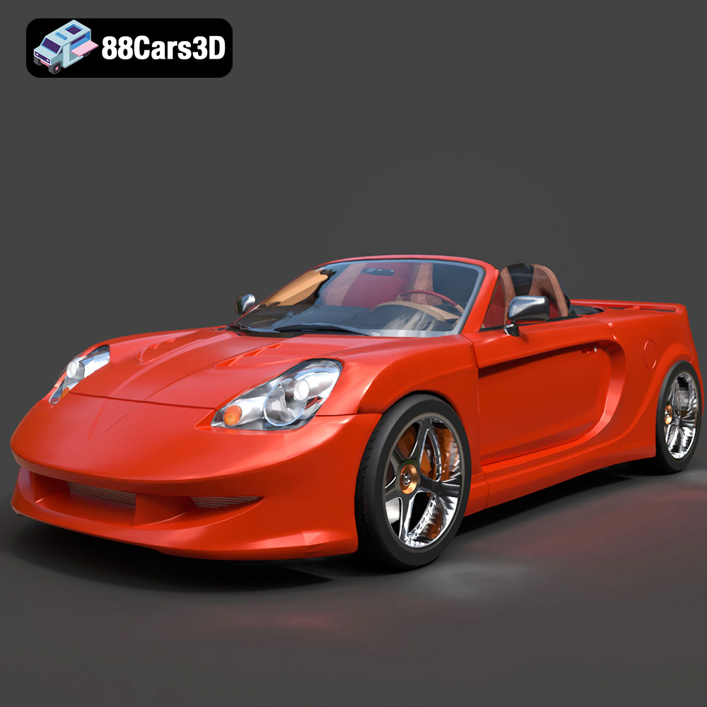
Download the Toyota MRS-007 3D Model featuring clean geometry, realistic detailing, and a fully modeled interior. Includes .blend, .fbx, .obj, .glb, .stl, .ply, .unreal, and .max formats for rendering, simulation, and game development.
Price: $10

Texture: Yes
Material: Yes
Download the Porsche 911 Turbo S 2024 3D Model featuring clean geometry, realistic detailing, and a fully modeled interior. Includes .blend, .fbx, .obj, .glb, .stl, .ply, .unreal, and .max formats for rendering, simulation, and game development.
Price: $20

Texture: Yes
Material: Yes
Download the Pontiac Solstice 2009 3D Model featuring clean geometry, realistic detailing, and a fully modeled interior. Includes .blend, .fbx, .obj, .glb, .stl, .ply, .unreal, and .max formats for rendering, simulation, and game development.
Price: $10

Texture: Yes
Material: Yes
Download the Mini Cooper Countryman 2025 3D Model featuring clean geometry, realistic detailing, and a fully modeled interior. Includes .blend, .fbx, .obj, .glb, .stl, .ply, .unreal, and .max formats for rendering, simulation, and game development.
Price: $29.9
Texture: Yes
Material: Yes
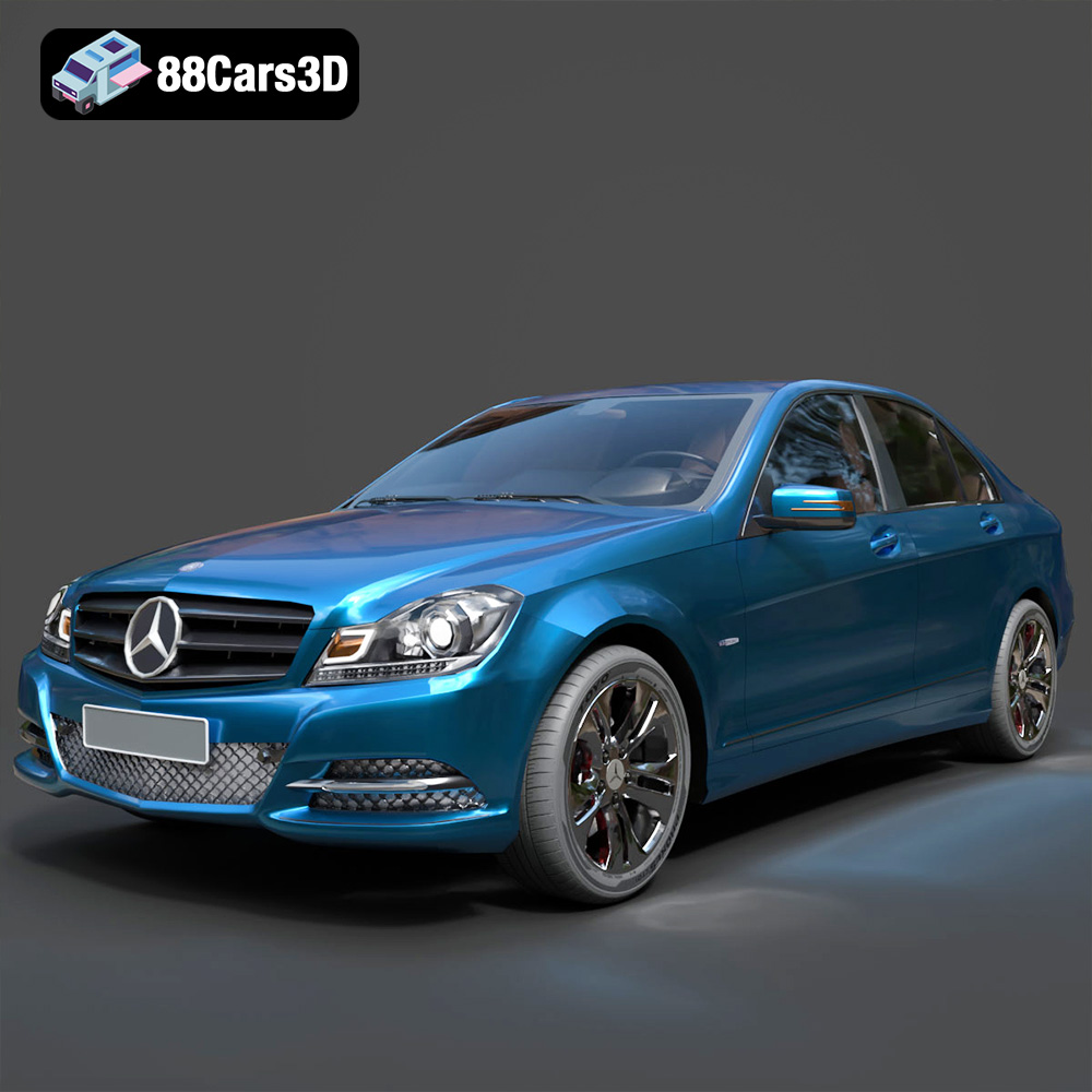
Download the Mercedes C Classe 2012 3D Model featuring clean geometry, realistic detailing, and a fully modeled interior. Includes .blend, .fbx, .obj, .glb, .stl, .ply, .unreal, and .max formats for rendering, simulation, and game development.
Price: $19.9
Texture: Yes
Material: Yes
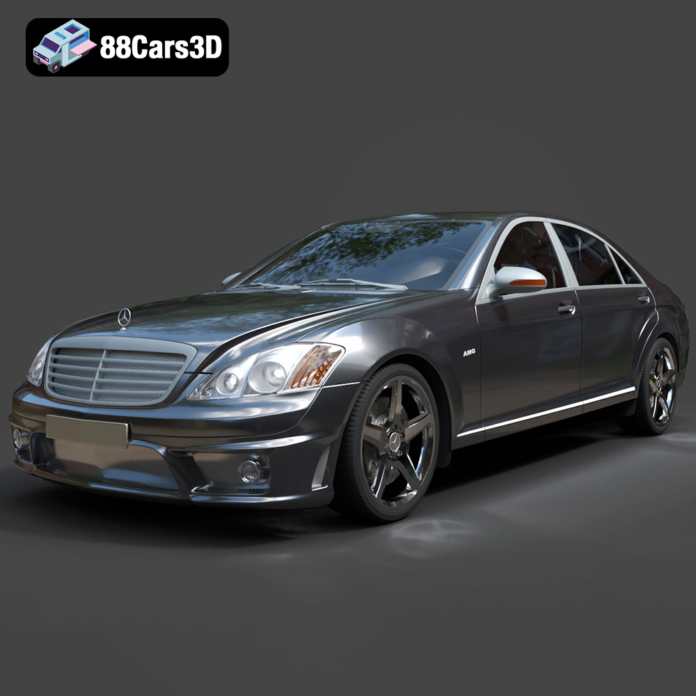
Download the Mercedes-Benz S65 AMG 2018 3D Model featuring clean geometry, realistic detailing, and a fully modeled interior. Includes .blend, .fbx, .obj, .glb, .stl, .ply, .unreal, and .max formats for rendering, simulation, and game development.
Price: $19.9

Texture: Yes
Material: Yes
Download the Mazda 3 Sedan 2004 3D Model featuring clean geometry, realistic detailing, and a fully modeled interior. Includes .blend, .fbx, .obj, .glb, .stl, .ply, .unreal, and .max formats for rendering, simulation, and game development.
Price: $10

Texture: Yes
Material: Yes
Download the Martin Rapide 2011 3D Model featuring clean geometry, realistic detailing, and a fully modeled interior. Includes .blend, .fbx, .obj, .glb, .stl, .ply, .unreal, and .max formats for rendering, simulation, and game development.
Price: $20.9

Texture: Yes
Material: Yes
Download the Car Tasergal 005 3D Model featuring clean geometry, realistic detailing, and a fully modeled interior. Includes .blend, .fbx, .obj, .glb, .stl, .ply, .unreal, and .max formats for rendering, simulation, and game development.
Price: $10
Texture: Yes
Material: Yes
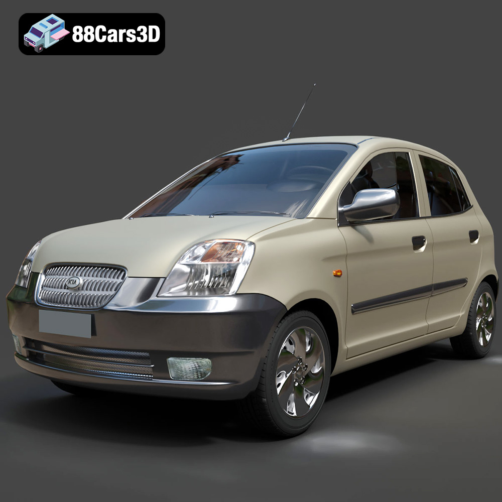
Download the Kia Picanto 2024 3D Model featuring clean geometry, realistic detailing, and a fully modeled interior. Includes .blend, .fbx, .obj, .glb, .stl, .ply, .unreal, and .max formats for rendering, simulation, and game development.
Price: $15.99

