
Advanced Topology Tips for Automotive 3D Modeling: Crafting Flawless Vehicles
In the high-octane world of automotive design and visualization, the difference between a good 3D car model and an exceptional one often boils down to its underlying topology. Far more than just a wireframe, optimal topology is the unseen armature that dictates everything from surface smoothness and deformation to rendering efficiency and animation fidelity. For professionals in rendering, game development, AR/VR experiences, and even 3D printing, mastering advanced topology techniques is not merely a skill—it’s a prerequisite for producing stunning, industry-standard automotive assets.
This comprehensive guide delves into the intricate art and science of automotive 3D modeling topology. We’ll dissect the critical principles of polygon flow, discuss the nuances of surface curvature, and explore how intelligent mesh construction impacts texturing, materials, and overall performance across various platforms. Whether you’re crafting high-resolution showroom renders or optimizing models for real-time game engines, understanding these advanced tips will empower you to build robust, beautiful, and versatile 3D car models that stand out. Prepare to elevate your automotive modeling prowess and unlock new levels of visual realism and technical precision.
The Foundation of Automotive Topology: Precision and Performance
At its core, automotive 3D modeling demands a meticulous approach to topology. Unlike organic modeling, where some degree of imperfection can be forgiven, vehicle surfaces are characterized by crisp lines, sprawling reflections, and perfect curvatures. Poor topology in this domain immediately manifests as pinching, distorted reflections, and inefficient rendering. The goal is always to achieve a clean, all-quad mesh that supports both subdivision surfacing for high-fidelity visuals and efficient deformation for animation or real-time applications.
A well-constructed automotive mesh minimizes render times, facilitates clean UV unwrapping, and ensures seamless integration into complex pipelines. It’s the difference between a static image and a dynamic asset that can be driven, animated, and interacted with flawlessly. Investing time in perfecting your topology from the outset saves countless hours in later stages of texturing, rigging, and rendering. Platforms like 88cars3d.com feature models meticulously crafted with these principles in mind, showcasing the visual and technical advantages of superior topology.
Understanding Polygon Flow and Edge Loops
Polygon flow, or edge flow, refers to the direction and continuity of edges on a 3D model. For automotive surfaces, achieving optimal polygon flow is paramount. Edges should follow the natural contours and design lines of the car, mimicking how light would travel across its surface. This means creating edge loops that define the primary forms (e.g., fender arches, door lines, hood creases) and then secondary loops that refine those forms and support curvature. Good edge flow ensures that when a subdivision surface modifier (like Meshsmooth in 3ds Max or Subdivision Surface in Blender) is applied, the model maintains its sharp details while smoothly transitioning across broader surfaces.
Key considerations for polygon flow include:
- Following Design Lines: Ensure edge loops align with the car’s body panels, vents, and character lines.
- Consistent Spacing: Maintain relatively even polygon distribution across smooth surfaces to prevent pinching or stretching during subdivision.
- Supporting Detail: Add denser edge loops around areas of high curvature or where sharp details are required, like headlight cutouts or panel gaps.
- Redundancy Reduction: Avoid unnecessary edge loops that add polygon count without contributing to form or detail.
Quad Dominance and Tri-strip Management
The golden rule in polygonal modeling, especially for subdivision surfaces, is to use quads (four-sided polygons) whenever possible. Quads subdivide predictably and evenly, leading to smooth, artifact-free surfaces. Triangles (three-sided polygons) can cause pinching or undesirable hard edges when subdivided, and N-gons (polygons with more than four sides) are generally problematic for subdivision, often leading to unpredictable and undesirable surface distortions. For real-time applications, triangles are the fundamental primitive, but starting with quads and converting to triangles at the final export stage ensures better control over the mesh.
While quads are ideal, triangles are sometimes unavoidable, particularly in areas of complex geometry or where faces merge. Strategic placement of triangles (e.g., in flat, non-deforming areas or tucked away where they won’t cause issues) is key. N-gons should be strictly avoided in subdivision-ready meshes. If you find yourself with an N-gon, always strive to convert it into an arrangement of quads and, if necessary, a minimal number of triangles in inconspicuous locations.
Target Polygon Counts for Different Applications
The “ideal” polygon count for an automotive model varies drastically depending on its intended use. Understanding these targets is crucial for efficient modeling. A high-resolution model for a cinematic render or a static visualization might have millions of polygons after subdivision, while a model for a mobile game or AR experience could be limited to tens of thousands.
- High-End Visualization/CGI: Often 500,000 to 2 million+ polygons (pre-subdivision models might be 50,000-200,000, subdividing to millions). Focus is on extreme detail, smooth reflections, and photographic realism.
- AAA Games (Next-Gen): Main vehicle models typically range from 80,000 to 150,000 triangles for the highest LOD, with multiple lower LODs.
- AR/VR/Mobile Games: Typically 15,000 to 50,000 triangles for the main model, often with fewer LODs or very aggressive optimization.
- 3D Printing: Polygon count can be higher, as long as the mesh is watertight and has no self-intersecting geometry. Focus is on manifold geometry rather than polycount for performance.
Always model with a clear target in mind. It’s easier to reduce polygon count (decimate) a high-detail mesh than to add detail to a low-poly one while maintaining quality topology.
Crafting Complex Curvatures and Smooth Surfaces
Automotive surfaces are a masterclass in complex curvature. From the sweeping arcs of a fender to the subtle depressions of a door panel, every curve must be flawlessly executed to capture the vehicle’s essence and reflect light realistically. Achieving this requires a deep understanding of how polygon density, edge support, and specific modeling techniques influence the final rendered form.
N-gons and their Careful Application/Avoidance
As discussed, N-gons are generally detrimental for subdivision surfaces due to their unpredictable behavior. However, there are niche scenarios where an N-gon might seem expedient, particularly on perfectly flat, non-deforming surfaces like a badge or a simple license plate. Even in these cases, it’s often better practice to maintain an all-quad mesh or triangulate the N-gon into clean triangles. If an N-gon is absolutely necessary, ensure it remains entirely flat and isolated from any areas that will be subdivided or deformed. The risk of rendering artifacts, especially with ray-tracing engines, often outweighs the minor convenience of using an N-gon.
Managing Creases and Hard Edges
Automotive design is replete with sharp creases, panel gaps, and hard edges that define the vehicle’s aesthetic. Replicating these convincingly in 3D while maintaining a smooth underlying mesh is a core challenge. The most common technique involves using “support loops” or “holding edges.” These are additional edge loops placed very close to a hard edge, effectively sharpening it when a subdivision surface modifier is applied. The closer the support loop to the main edge, the sharper the resulting crease.
In Blender 4.4, the Bevel modifier (see Blender 4.4 documentation on Bevel Modifier) offers a powerful and non-destructive way to create controlled hard edges. By applying a Bevel modifier with a small number of segments and a specific width, you can create a rounded or chamfered edge that mimics real-world manufacturing tolerances. This is often superior to purely relying on support loops, as it provides more control and can be adjusted dynamically. Combining support loops with strategic beveling offers the most robust solution for achieving both sharpness and controlled softening where needed.
Sculpting vs. Subdivision Modeling for Automotive Forms
Traditionally, automotive modeling has relied heavily on polygon modeling and subdivision surfaces, building up complex forms from basic primitives and refining them with edge manipulation. This approach excels at precision, clean topology, and control over exact curvature. However, modern workflows increasingly incorporate sculpting techniques, particularly for organic-like details or concept phases.
Sculpting in tools like ZBrush or Blender’s sculpt mode (refer to Blender 4.4 documentation on Sculpt Mode) can rapidly generate complex shapes, especially for interior components or tire treads. The challenge with sculpting for automotive exteriors is that it often produces dense, triangulated, or messy topology unsuitable for subdivision. The solution is often a hybrid approach: sculpt initial concepts or intricate details, then retopologize the high-detail sculpt into a clean, quad-based mesh suitable for subdivision surfacing. This allows artists to leverage the speed of sculpting while retaining the precision and flexibility of traditional polygon modeling for the final production asset.
UV Mapping Strategies for Flawless Textures
Even the most perfectly modeled car will look flat and unrealistic without well-executed textures. UV mapping is the crucial bridge between your 3D geometry and 2D image textures, dictating how materials wrap around your model. For automotive assets, achieving clean, efficient, and distortion-free UVs is particularly challenging due to the complex, often sprawling surfaces and the need for realistic reflections and decals.
Non-overlapping UVs and Texel Density Consistency
The cardinal rule for professional UV mapping is to ensure non-overlapping UV islands. Overlapping UVs lead to texture bleeding, issues with baking (ambient occlusion, normal maps), and unpredictable results in game engines. Every face on your 3D model should have a unique position on the UV map.
Equally important is maintaining consistent texel density across the entire model. Texel density refers to the number of pixels per unit of surface area on your model. Inconsistent texel density means some parts of your car will have sharp, high-resolution textures while others appear blurry and pixelated. Tools within 3ds Max, Blender, and Maya allow you to visualize and normalize texel density, ensuring uniform texture clarity. For example, a headlight might need higher texel density than a less prominent undercarriage component, but within each major component (body panel, interior seat, wheel), consistency is key.
Seam Placement and Hard Surface UV Unwrapping
Strategic seam placement is fundamental to minimizing distortion and hiding visible texture breaks. For automotive models, seams should ideally follow natural breaks in the geometry, such as panel gaps, edges of different material types, or hard creases. Avoid placing seams in highly visible, smooth areas that will reflect light prominently, as this can lead to noticeable texture stretching or discontinuities.
Hard surface UV unwrapping often involves segmenting the model into logical, flatter pieces that are then arranged efficiently on the UV atlas. For car bodies, this often means unwrapping each major panel (hood, roof, doors, fenders) as a separate UV island. Specialized tools like “RoadKill UV” or Blender’s “Follow Active Quads” (see Blender 4.4 documentation on UV Unwrapping) can greatly assist in straightening and optimizing UV layouts for hard-surface models, reducing distortion and making texture painting easier.
Multi-tile UVs (UDIM) for High-Resolution Assets
For ultra-high-resolution automotive models, a single 0-1 UV space is often insufficient to achieve the desired texel density. This is where UDIM (U-Dimension) or multi-tile UVs come into play. UDIM allows you to spread your UV islands across multiple UV tiles (e.g., 1001, 1002, 1003…), effectively giving you more texture space. This is commonly used in film production and high-end visualization to accommodate extremely detailed textures, where different body panels, interior elements, or intricate components each get their own dedicated texture space.
While UDIM increases texture memory footprint, it offers unparalleled control over texture resolution and is essential for achieving photorealistic results on sprawling automotive surfaces. Most modern rendering engines (Corona, V-Ray, Cycles, Arnold) and texturing software (Substance Painter, Mari) fully support UDIM workflows. When sourcing models from marketplaces such as 88cars3d.com for high-fidelity projects, look for models that utilize UDIMs for optimal texture detail.
PBR Material Creation and Shader Networks
Physically Based Rendering (PBR) has revolutionized the way 3D artists create realistic materials. For automotive models, PBR is indispensable for accurately simulating the complex interplay of light with car paint, glass, rubber, metal, and leather. Understanding PBR principles and how to construct robust shader networks is key to achieving visual fidelity.
Principles of Physically Based Rendering (Metallic/Roughness vs. Specular/Glossiness)
PBR is based on scientific principles that accurately describe how light interacts with surfaces, resulting in predictable and consistent rendering across various lighting conditions. The two primary PBR workflows are Metallic/Roughness and Specular/Glossiness. Both aim for the same result but use different map inputs:
- Metallic/Roughness:
- Albedo/Base Color: Defines the base color of the surface. For metals, this is the color of the metal; for dielectrics (non-metals), it’s the diffuse color.
- Metallic: A grayscale map where black (0) represents a dielectric and white (1) represents a metal. Intermediate values are generally avoided.
- Roughness: A grayscale map where black (0) is perfectly smooth/mirror-like and white (1) is completely rough/matte.
- Specular/Glossiness:
- Diffuse: Defines the diffuse color for dielectrics.
- Specular: Defines the color and intensity of specular reflections. For metals, this map is often colored and directly controls reflectivity.
- Glossiness: The inverse of roughness; black (0) is rough, white (1) is perfectly smooth.
Most modern engines and renderers (like Blender’s Principled BSDF or Unreal Engine’s standard material) primarily use the Metallic/Roughness workflow due to its simplicity and intuitive nature. Consistency within your asset pipeline is crucial—stick to one workflow.
Crafting Realistic Car Paint Shaders (Flakes, Clear Coat)
Car paint is one of the most complex materials to replicate due to its multi-layered structure. A realistic car paint shader typically involves:
- Base Color Layer: The primary color of the paint, often driven by an Albedo map.
- Metallic Flakes: A crucial component for metallic paints. This is usually simulated by a noise texture (e.g., Voronoi or Perlin noise) plugged into the normal input of the material, creating tiny, randomized reflections that mimic the metallic particles in the paint. The scale and intensity of this noise are critical.
- Clear Coat Layer: A transparent, highly reflective layer on top, simulating the protective clear coat. This is often implemented as a separate layer with its own roughness/glossiness and an Index of Refraction (IOR) value (typically around 1.5). The clear coat also needs a “falloff” or “Fresnel” effect to control its reflectivity based on viewing angle, making reflections stronger at glancing angles.
- Orange Peel/Imperfections: Subtle surface imperfections, like a very fine “orange peel” texture or dust, can be added via a very subtle normal map or roughness map to enhance realism.
Building these complex shaders often involves creating intricate shader networks using nodes in software like Blender (Shader Editor, see Blender 4.4 documentation on Shader Nodes) or 3ds Max (Slate Material Editor).
Material Instancing and Optimization
For game engines and large-scale visualizations, efficient material management is paramount. Material instancing allows you to create variations of a base material without duplicating its entire shader network. For example, you can have a “Car_Paint_Master” material and then create instances for “Car_Paint_Red,” “Car_Paint_Blue,” etc., by simply changing color parameters while sharing the underlying shader logic. This significantly reduces memory usage and improves rendering performance by minimizing draw calls.
Other material optimizations include:
- Texture Atlasing: Combining multiple smaller textures into one larger texture map to reduce texture swaps and draw calls.
- Baked Textures: Baking complex lighting (e.g., ambient occlusion, global illumination) or procedural details into static textures for real-time performance.
- Shader Complexity Reduction: Simplifying shader networks by removing unnecessary nodes or calculations for less critical assets or lower-end platforms.
Optimization for Game Engines and Real-Time Applications
While high-fidelity renders prioritize visual perfection, game engines and real-time applications demand a careful balance between visual quality and performance. Automotive models for interactive experiences require rigorous optimization to ensure smooth frame rates and efficient resource utilization.
Level of Detail (LODs) and Decimation Techniques
Level of Detail (LOD) systems are fundamental for optimizing models in real-time environments. Instead of rendering a single high-polygon model at all distances, LODs involve creating multiple versions of the same model, each with progressively fewer polygons. As the camera moves further away from the object, the engine automatically switches to a lower-polygon LOD, significantly reducing the computational load without a noticeable drop in visual quality. A typical setup might involve 3-5 LODs:
- LOD0: Highest detail, rendered when close to the camera (e.g., 80,000-150,000 triangles).
- LOD1: Medium detail, used at intermediate distances (e.g., 30,000-50,000 triangles).
- LOD2: Low detail, for distant views (e.g., 5,000-15,000 triangles).
- LOD3/LOD4: Very low detail or billboard for extreme distances (e.g., 500-2,000 triangles or a simple textured plane).
Decimation tools (like Blender’s Decimate modifier or external tools like InstaLOD) are used to automatically reduce polygon count while trying to preserve mesh shape and UVs. Careful manual cleanup and normal map baking (from high-poly to low-poly) are often required to ensure visual quality across LODs.
Draw Call Reduction and Texture Atlasing
Draw calls are instructions from the CPU to the GPU to render a set of primitives. Each draw call carries an overhead, so minimizing them is critical for performance. For automotive models, this often means:
- Combining Meshes: Merging multiple separate mesh objects (e.g., body panels, interior parts) into a single mesh where appropriate, as long as they share the same material.
- Texture Atlasing: As mentioned in the PBR section, combining multiple smaller textures (e.g., for different car parts like headlights, tail lights, badges) into one larger texture atlas. This means the GPU only needs to bind one texture instead of several, reducing draw calls.
- Material Instancing: Using instances of a master material also helps reduce draw calls by allowing the engine to batch similar materials.
Collision Meshes and Performance Budgets
For interactive game environments, cars often require collision meshes. These are simplified, low-polygon versions of the main model used exclusively for physics calculations. They don’t need to be visually appealing, only accurate enough to represent the car’s physical bounds. Using a complex visual mesh for collision detection is extremely inefficient. Often, a few convex hull shapes or a very basic box primitive can serve as an effective collision mesh, drastically reducing physics processing overhead.
Understanding and adhering to a “performance budget” is crucial. This budget defines limits for polygon count, texture memory, material complexity, and draw calls for a given asset or scene. For example, a single vehicle in a mobile game might have a budget of 30,000 triangles and 4 x 1024×1024 textures. Meeting these budgets requires careful planning and continuous optimization throughout the modeling and texturing process.
Rendering and Visualization Workflows
Once your automotive model is meticulously crafted and textured, the final stage is bringing it to life through rendering. This is where all the hard work on topology, UVs, and materials culminates in a visually stunning image or animation. Mastering rendering workflows involves understanding lighting, camera composition, and post-processing techniques.
Lighting Setups for Automotive Renders (HDRI, Studio Lighting)
Effective lighting is perhaps the most critical element in automotive rendering. It defines the mood, highlights the car’s form, and makes surfaces gleam realistically. Two primary approaches dominate:
- HDRI (High Dynamic Range Image) Lighting: HDRI environments are panoramic images that capture real-world lighting information (color, intensity, direction). Using an HDRI as an environment map in your renderer provides realistic, nuanced global illumination and reflections with minimal setup. This is ideal for showing cars in outdoor settings or reflective studio environments. Combine HDRIs with targeted area lights or reflectors to enhance specific highlights and shadows.
- Studio Lighting: Mimics professional photography studios using a combination of area lights, planes, and often light-blocking geometry (lightboxes). Common setups include:
- Three-Point Lighting: Key light (main source), fill light (softens shadows), and back/rim light (separates car from background).
- Softbox/Strip Lights: Large, rectangular lights that create soft, elongated reflections characteristic of professional car photography.
- Reflectors: Invisible planes with emissive materials or high reflectivity to bounce light onto specific areas of the car.
Experimentation is key, but always consider how light interacts with the car’s curves and paint finish.
Camera Angles and Composition for Impact
Just like a photographer, a 3D artist must compose their shots carefully. For automotive rendering, effective camera work can emphasize design features, convey speed, or evoke emotion:
- Low Angles: Emphasize power and presence, making the car look larger and more imposing.
- Dynamic Angles: Use slight Dutch tilts or follow-through shots to create a sense of motion.
- Leading Lines: Utilize the car’s body lines or environmental elements to guide the viewer’s eye.
- Rule of Thirds: Position the car or key features along the grid lines or intersections to create balanced and engaging compositions.
- Depth of Field: Use a shallow depth of field to draw attention to specific details (e.g., a wheel, a badge) while blurring the background.
Understanding real-world automotive photography can greatly inform your 3D camera setup. Don’t just place a camera; compose a shot.
Post-processing and Color Grading Techniques
The render straight out of your 3D software is rarely the final product. Post-processing in tools like Photoshop, Affinity Photo, or even directly in renderers like Corona Renderer’s LightMix or Blender’s Compositor (see Blender 4.4 documentation on Compositor) is essential for adding that professional polish. Key post-processing steps include:
- Exposure and Contrast Adjustment: Fine-tuning the overall brightness and dynamic range.
- Color Grading: Adjusting color balance, saturation, and vibrancy to create a specific mood or aesthetic.
- Vignetting: Adding a subtle darkening around the image edges to draw focus to the center.
- Chromatic Aberration: A subtle lens effect that can add a touch of realism.
- Glow/Bloom: Enhancing bright areas, like headlights or reflections, with a soft glow.
- Sharpening: Lightly sharpening details to make the image crisper.
- Noise Reduction: Cleaning up any residual noise from the rendering process.
These techniques transform a raw render into a polished, print-ready or production-ready image. Many modern renderers offer built-in post-processing tools, but external image editors provide greater control and flexibility.
File Formats, AR/VR, and 3D Printing Considerations
The journey of a 3D automotive model doesn’t end with a beautiful render. It often needs to be shared, integrated into interactive experiences, or even physically manufactured. This requires careful consideration of file formats, optimization for emerging technologies like AR/VR, and preparation for 3D printing.
Choosing the Right File Format (FBX, OBJ, GLB, USDZ, STL)
Selecting the appropriate file format is crucial for compatibility and maintaining data integrity:
- FBX (Filmbox): A proprietary format by Autodesk, widely considered the industry standard for exchanging 3D data between DCC (Digital Content Creation) applications (e.g., 3ds Max, Maya, Blender) and game engines (Unity, Unreal Engine). It supports meshes, materials, textures, animations, and cameras.
- OBJ (Wavefront Object): A universal, open standard format for geometry. It’s highly compatible but typically only stores mesh data, UVs, and references to materials (MTL file). It doesn’t support animations or advanced material properties.
- GLB (Binary GL Transmission Format): An open standard, royalty-free format for 3D scenes and models. It’s highly optimized for web and real-time applications, storing geometry, materials (PBR), animations, and textures in a single, self-contained binary file. Ideal for AR/VR and web-based viewers.
- USDZ (Universal Scene Description Zip): Apple’s proprietary format built on Pixar’s USD. Highly optimized for AR on iOS devices, supporting PBR materials, animations, and light weight.
- STL (Stereolithography): A standard format for 3D printing. It only describes the surface geometry of a 3D object as a raw, unstructured triangulated surface. It doesn’t store color, texture, or material information.
Always consider the end-use of your model when exporting. For general exchange, FBX is versatile. For web or AR/VR, GLB and USDZ are specialized and highly efficient. For 3D printing, STL is the go-to.
AR/VR Optimization (Polycount, Draw Calls, Material Complexity)
AR/VR environments impose some of the strictest performance demands. Automotive models for these platforms must be aggressively optimized to maintain comfortable frame rates (typically 90 FPS or higher) and prevent motion sickness. Key optimization strategies include:
- Extremely Low Polycount: Often significantly lower than typical game assets. LODs are essential, and even the highest LOD should be very lean.
- Minimized Draw Calls: Combining meshes and using texture atlases is critical.
- Simplified Materials: Using simple PBR shaders with minimal texture maps. Avoid complex shader networks, transparent effects, or real-time reflections unless absolutely necessary and well-optimized.
- Baked Lighting: Pre-baking global illumination and shadows into lightmap textures rather than calculating them in real-time.
- Occlusion Culling: Hiding objects that are not visible to the camera (e.g., parts of the engine hidden by the body).
- Static Batching: Merging static meshes into larger batches to reduce draw calls.
The goal is to provide a convincing visual experience while staying well within the performance budget of the target AR/VR hardware. This is an area where models from 88cars3d.com can provide a solid foundation, as many are designed with clean topology ready for further optimization.
Preparing Models for 3D Printing (Watertight Meshes, Wall Thickness)
Converting a visualization model into a 3D printable asset requires a different set of considerations:
- Watertight Mesh (Manifold): The model must be a completely closed volume with no holes, inverted normals, or self-intersecting geometry. Imagine filling the model with water—no water should leak out. This is crucial for slicing software to correctly interpret the model. Tools like Blender’s 3D Print Toolbox (an add-on) or dedicated mesh repair software can help identify and fix these issues.
- Wall Thickness: Ensure all surfaces have a sufficient wall thickness to be physically printed. Thin walls can break easily or fail to print. The minimum thickness depends on the printing technology and material (e.g., often 0.8mm – 2mm).
- Scale and Units: Models must be scaled correctly to the desired physical dimensions and exported in the correct units (millimeters, centimeters, inches).
- Polygon Count: While not as critical as for real-time, excessively high polygon counts can lead to large file sizes and slow slicing times. Decimate the mesh where fine detail isn’t required, but ensure enough resolution to capture curves and details.
- No N-gons or Internal Geometry: Remove any internal, non-visible geometry that would just add unnecessary complexity to the print.
Always perform a thorough pre-print check using specialized software before sending a model to a 3D printer.
Conclusion
Mastering advanced topology in automotive 3D modeling is an ongoing journey that requires precision, technical understanding, and an artistic eye. From the foundational principles of clean quad flow and strategic edge loops to the intricacies of PBR material creation and performance optimization for real-time applications, every step contributes to the final realism and versatility of your 3D car models. Whether you are crafting cinematic masterpieces, designing immersive AR/VR experiences, or preparing for high-fidelity 3D prints, the quality of your underlying mesh dictates success.
By diligently applying the techniques discussed—from thoughtful polygon placement and smart UV mapping to efficient material instancing and rigorous optimization—you empower your automotive assets to excel across diverse platforms and use cases. Remember, a superior 3D model isn’t just about what’s visible; it’s about the robust, meticulously constructed framework beneath the surface. Continue to refine your skills, leverage industry best practices, and pay attention to every technical detail. Your dedication to advanced topology will undoubtedly set your 3D automotive creations apart, driving them toward unparalleled levels of quality and realism.
Featured 3D Car Models
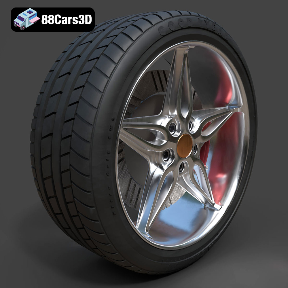
Wheel-001 Component 3D Model
Texture: Yes
Material: Yes
Download the Wheel-001 Component 3D Model featuring clean geometry, realistic detailing, and a fully modeled interior. Includes .blend, .fbx, .obj, .glb, .stl, .ply, .unreal, and .max formats for rendering, simulation, and game development.
Price: $10.99
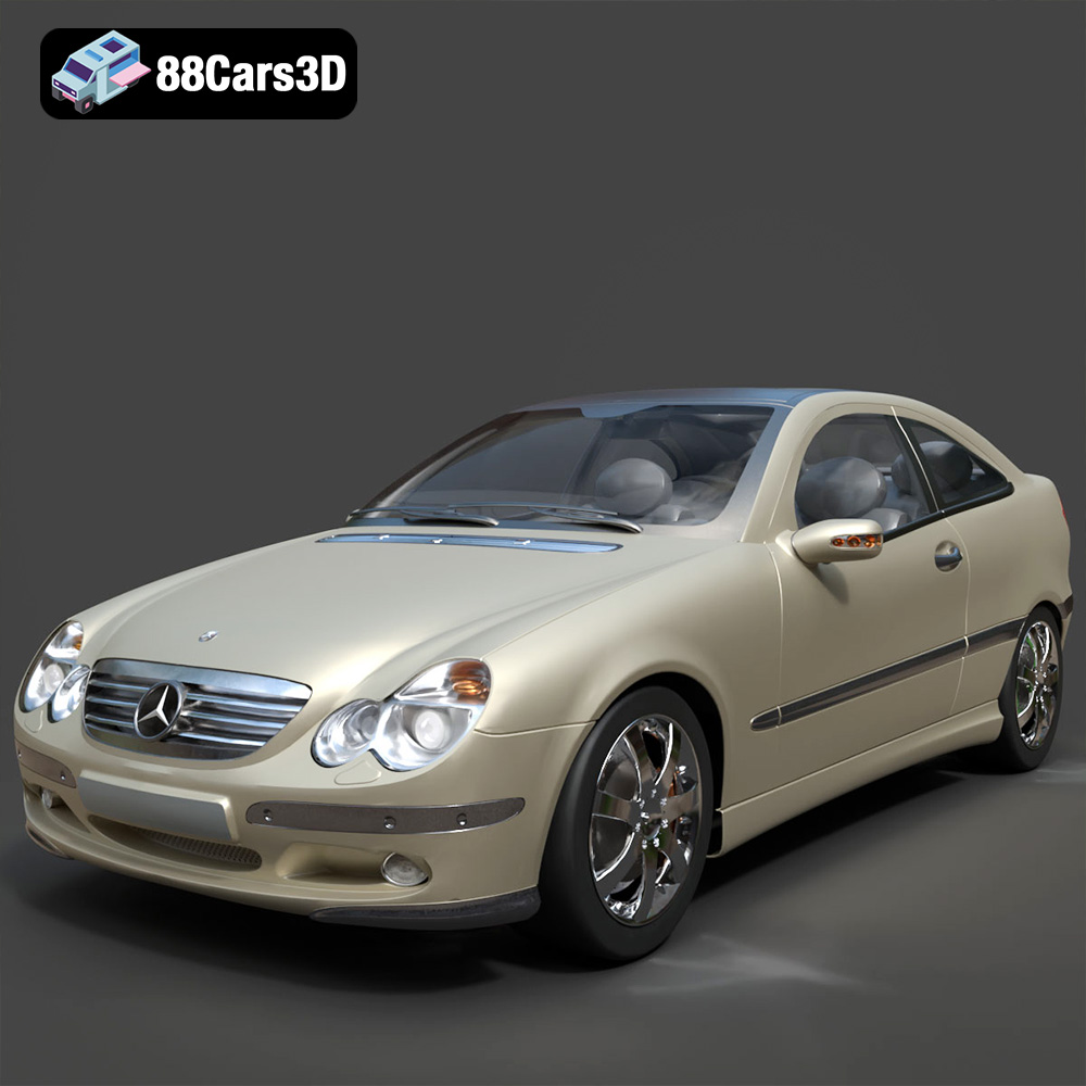
Mercedes Benz C230 3D Model
Texture: Yes
Material: Yes
Download the Mercedes Benz C230 3D Model featuring clean geometry, realistic detailing, and a fully modeled interior. Includes .blend, .fbx, .obj, .glb, .stl, .ply, .unreal, and .max formats for rendering, simulation, and game development.
Price: $14.99
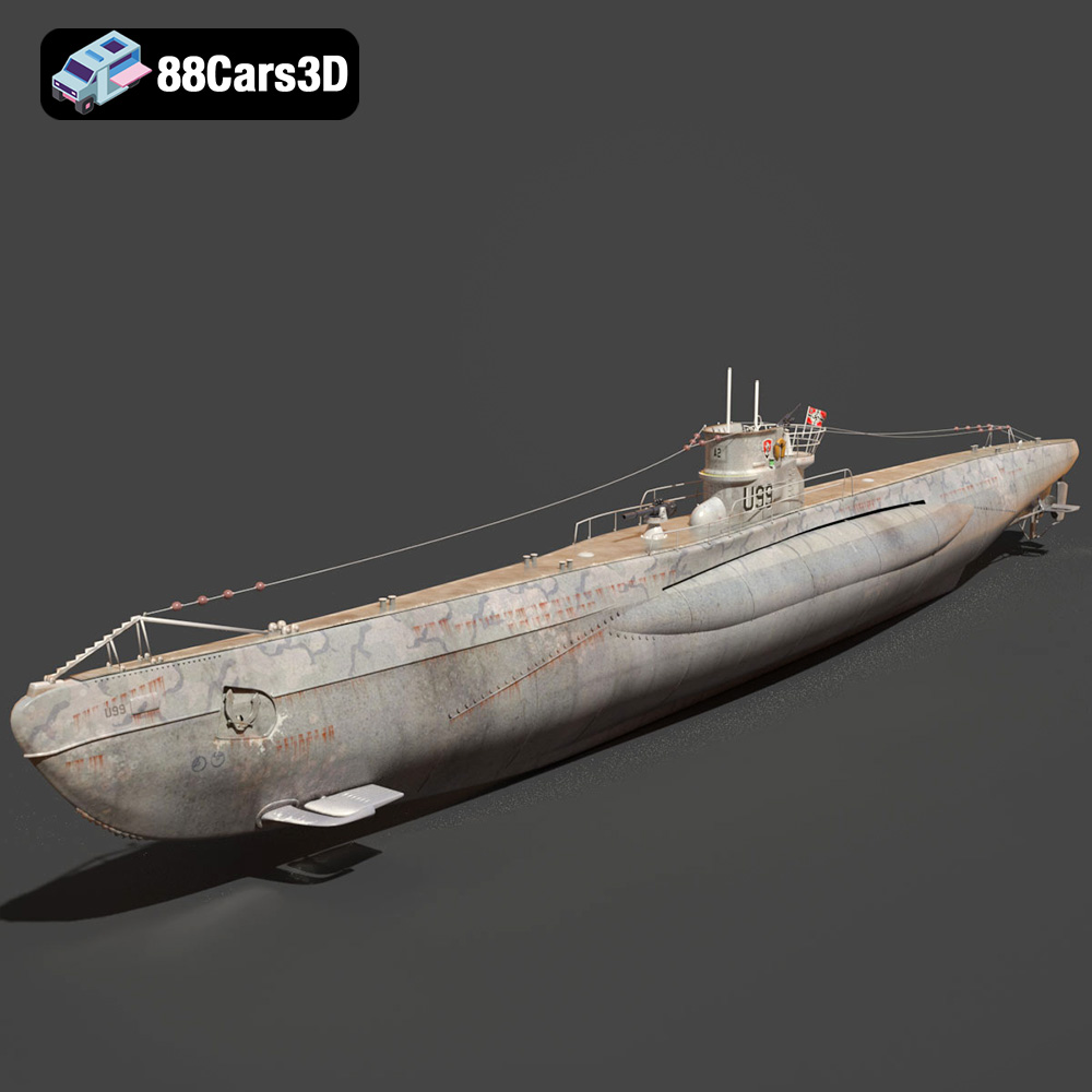
German U-Boat U-99 Submarine 1940 3D Model
Texture: Yes
Material: Yes
Download the German U-Boat U-99 Submarine 3D Model featuring clean geometry, realistic detailing, and a fully modeled interior. Includes .blend, .fbx, .obj, .glb, .stl, .ply, .unreal, and .max formats for rendering, simulation, and game development.
Price: $10
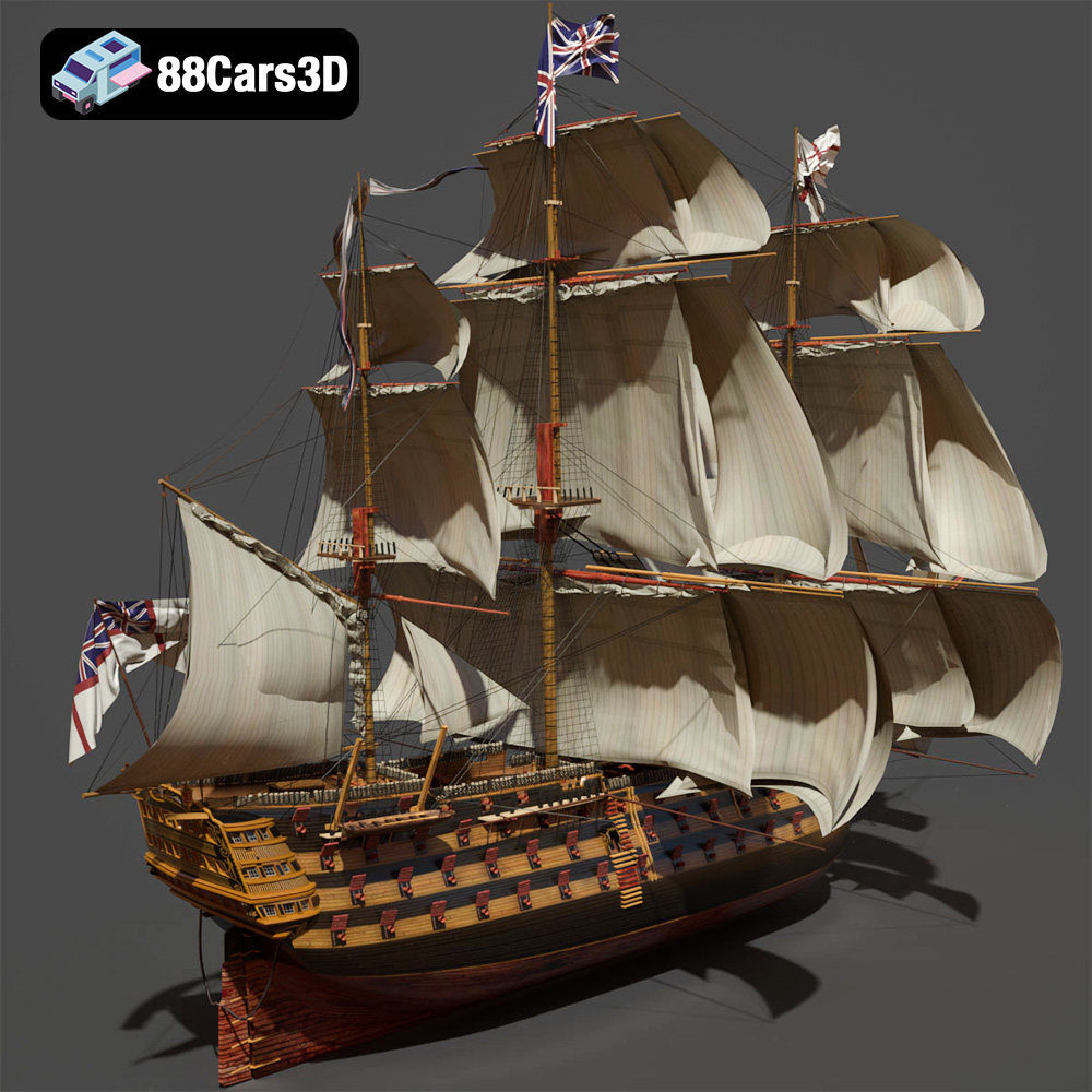
KEMA ELKANLI-001 3D Model
Texture: Yes
Material: Yes
Download the KEMA ELKANLI-001 3D Model featuring clean geometry, realistic detailing, and a fully modeled interior. Includes .blend, .fbx, .obj, .glb, .stl, .ply, .unreal, and .max formats for rendering, simulation, and game development.
Price: $9.99
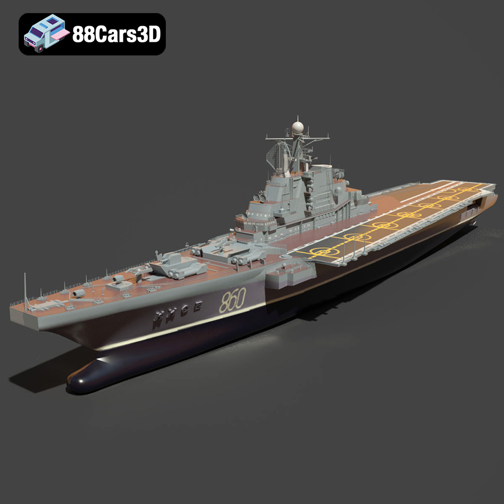
Soviet aircraft carrier Kiev 3D Model
Texture: Yes
Material: Yes
Download the Carrier 006 3D Model featuring a robust design and detailed components. Includes .blend, .fbx, .obj, .glb, .stl, .ply, .unreal, and .max formats for rendering, simulation, and game development.
Price: $10.79
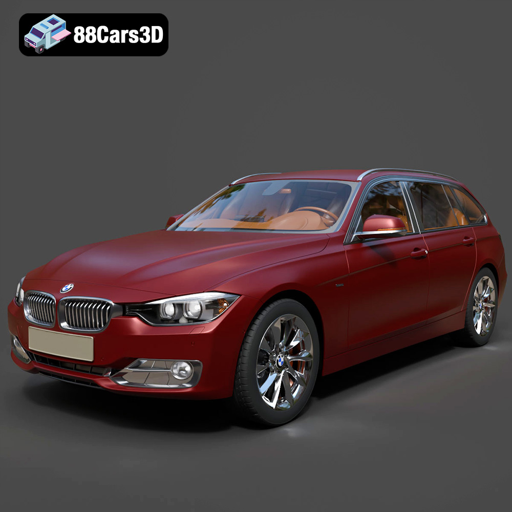
BMW 3 series Touring 335i (F31) 2013 3D Model
Texture: Yes
Material: Yes
Download the BMW 3 series Touring 335i (F31) 2013 3D Model featuring a highly detailed exterior, realistic interior, and modular design. Includes .blend, .fbx, .obj, .glb, .stl, .ply, .unreal, and .max formats for rendering, simulation, and game development.
Price: $30.79
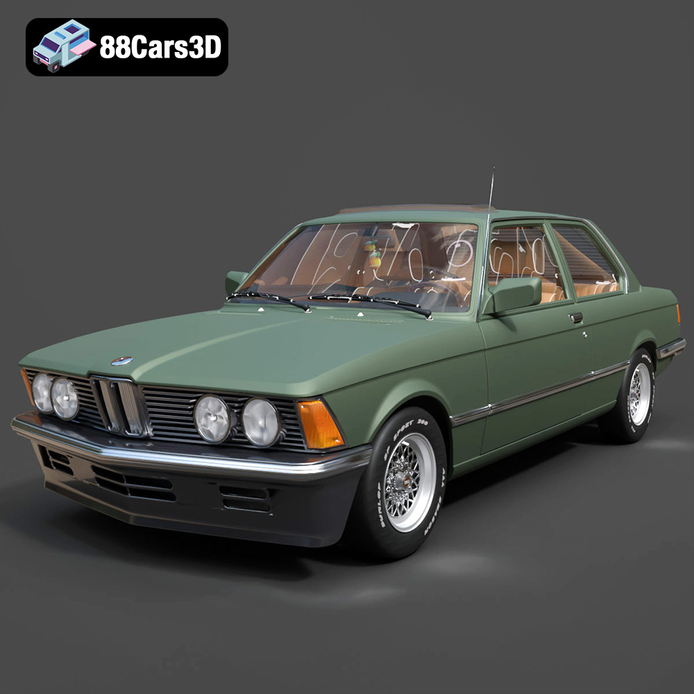
BMW 3 Series E21 3D Model
Texture: Yes
Material: Yes
Download the BMW 3 Series E21 3D Model featuring authentic exterior design, detailed interior, and accurate proportions. Includes .blend, .fbx, .obj, .glb, .stl, .ply, .unreal, and .max formats for rendering, simulation, and game development.
Price: $20.79
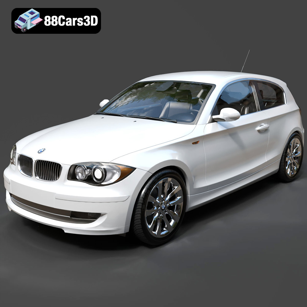
BMW 1 Series 3-Door E81 3D Model
Texture: Yes
Material: Yes
Download the BMW 1 Series 3-Door E81 3D Model featuring a detailed exterior, functional interior elements, and clean geometry. Includes .blend, .fbx, .obj, .glb, .stl, .ply, .unreal, and .max formats for rendering, simulation, and game development.
Price: $14.79
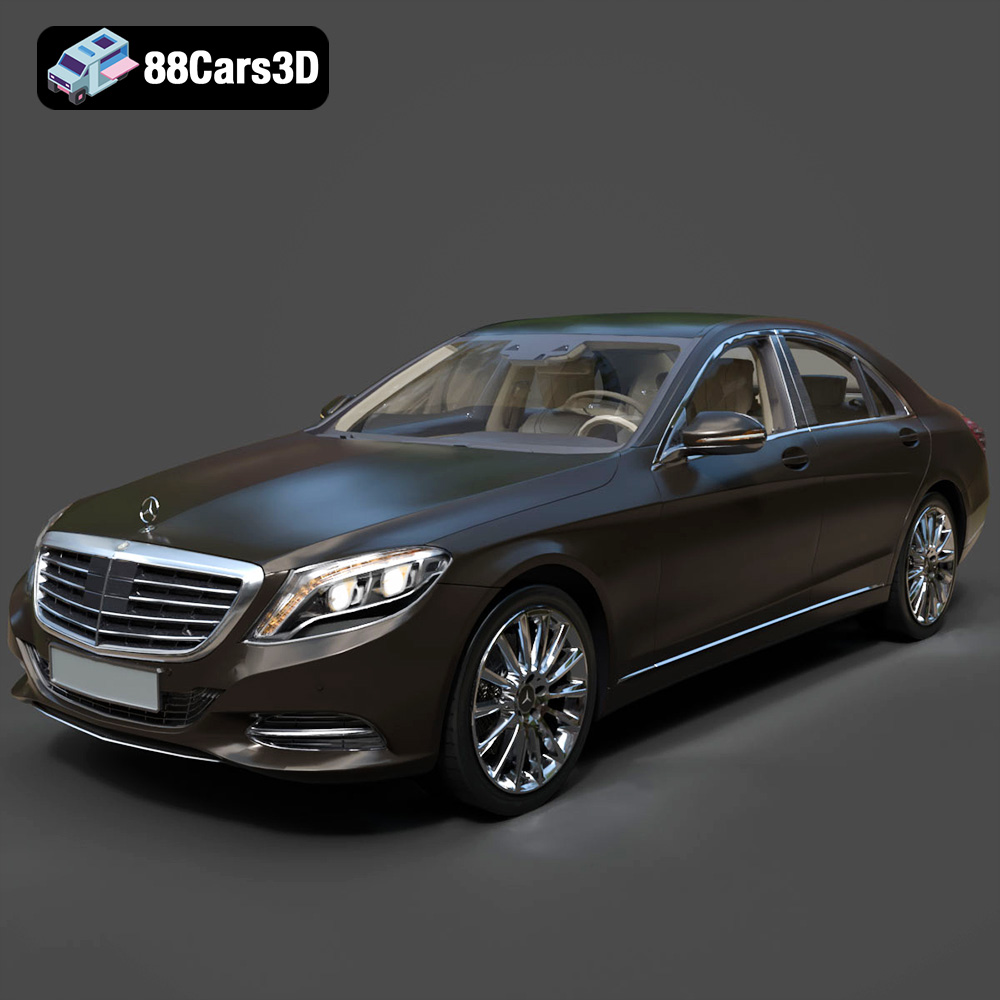
Mercedes-Benz S500 2022 3D Model
Texture: Yes
Material: Yes
Download the Mercedes-Benz S500 2022 3D Model featuring clean geometry, realistic detailing, and a fully modeled interior. Includes .blend, .fbx, .obj, .glb, .stl, .ply, .unreal, and .max formats for rendering, simulation, and game development.
Price: $19.99
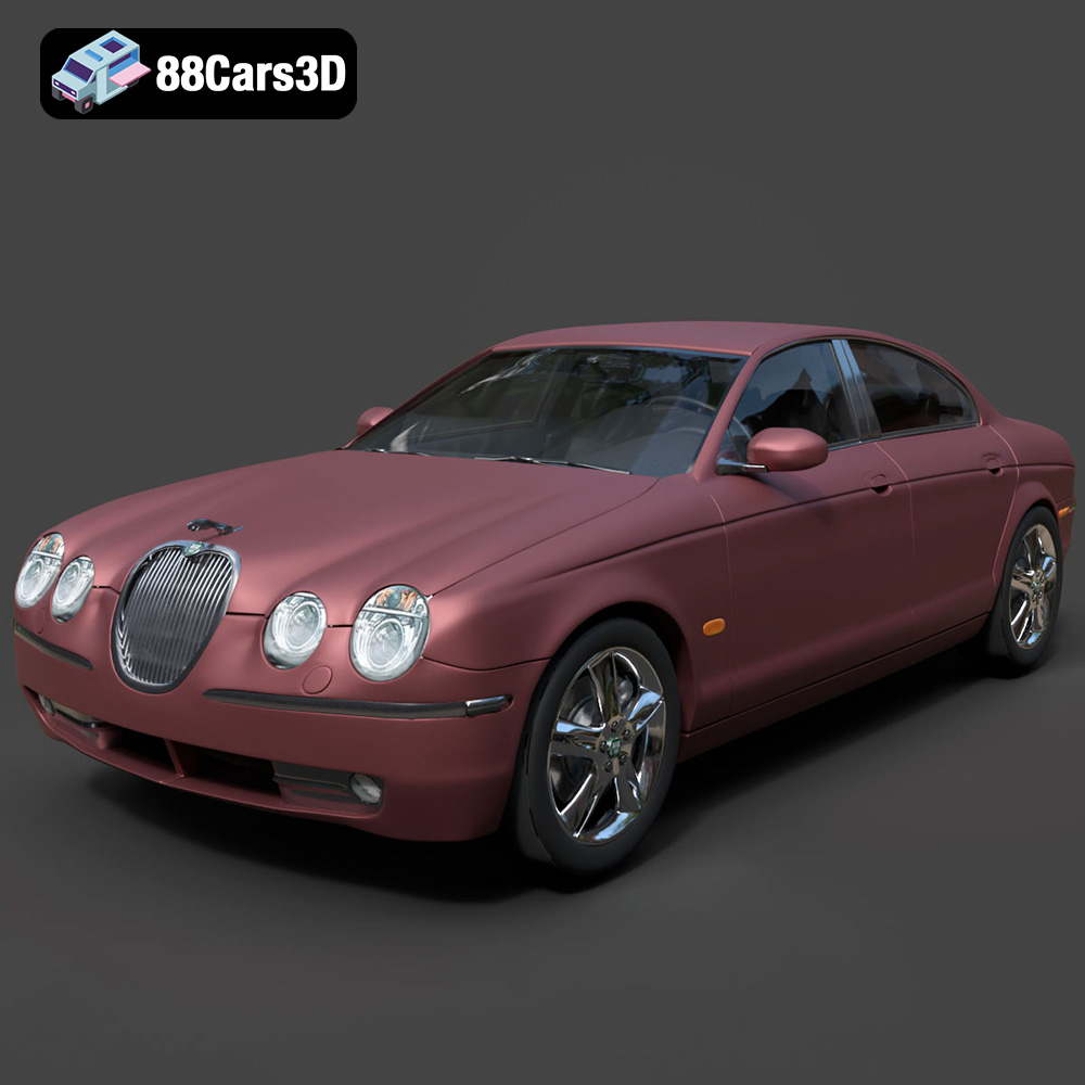
Jaguar S-Type Sedan 3D Model
Texture: Yes
Material: Yes
Download the Jaguar S-Type Sedan 3D Model featuring clean geometry, realistic detailing, and a fully modeled interior. Includes .blend, .fbx, .obj, .glb, .stl, .ply, .unreal, and .max formats for rendering, simulation, and game development.
Price: $18.99
