
“`html
Mastering Complex Geometry: A Guide to Printing Intricate STL Files Without Failures
The world of 3D printing opens up a universe of possibilities, allowing hobbyists and professionals alike to bring intricate designs to life. From detailed automotive models to complex mechanical parts, the ability to print challenging geometries is a hallmark of advanced additive manufacturing. However, these complex designs, often rich with overhangs, thin walls, and delicate features, can be a significant hurdle, frequently leading to frustrating print failures. This guide is designed to equip you with the knowledge and techniques needed to navigate these printing challenges. We’ll delve into the critical aspects of STL file preparation, optimal slicing strategies, effective support generation, and the nuances of material selection and printer calibration. By understanding these elements, you’ll be able to confidently tackle even the most demanding STL files and achieve consistently successful, high-quality prints. Get ready to transform your printing capabilities and elevate your creations from good to extraordinary.
Understanding the Nature of Complex STL Files
Complex geometries in STL files present unique challenges primarily due to the way they interact with the layer-by-layer additive manufacturing process. An STL file, at its core, represents a 3D model’s surface geometry using a collection of interconnected triangles. While this is a universal format, the ‘density’ and ‘orientation’ of these triangles can dictate how easily a model can be sliced and printed. For intricate car models, for instance, features like sharp spoilers, recessed grilles, delicate interior components, or even complex wheel spokes can introduce significant overhangs and undercuts. These are areas where new layers of plastic need to be extruded without any underlying support from previously printed layers.
The inherent nature of FDM (Fused Deposition Modeling) printing, which relies on extruding molten plastic onto a heated bed or previous layer, means that unsupported sections are highly susceptible to gravity. This can lead to drooping, stringing, or complete collapse of the feature during the printing process. Resin printing (SLA/DLP/MSLA) also faces similar challenges with overhangs, though often to a lesser degree due to the curing process and the ability to print finer details. However, excessive overhangs in resin printing can lead to peel forces during layer separation, potentially detaching the print from the build plate or causing layer adhesion failures. Understanding these fundamental limitations is the first step toward preventing print failures.
Mesh Topology and Manifold Integrity
A crucial aspect of complex STL files is their mesh topology. A “manifold” or “watertight” mesh is one that defines a closed volume without any holes, internal faces, or intersecting triangles. Non-manifold meshes are a common source of problems in slicing software, leading to unpredictable results, incorrect support generation, and outright print failures. For example, a car model with a grille that isn’t properly enclosed, or a component with internal faces where none should exist, can confuse the slicer. Software like Meshmixer, Blender, or dedicated tools like Autodesk Netfabb are invaluable for inspecting and repairing these mesh issues. These tools allow you to identify non-manifold edges, flipped normals (where triangles face inwards instead of outwards), and self-intersecting geometry, ensuring the digital model accurately represents a printable object.
Overhangs, Undercuts, and Bridges
These are the primary culprits behind failed prints of complex objects.
- Overhangs: Features that extend outwards at an angle greater than 45-60 degrees from the vertical axis typically require support. A sharp spoiler on a 3D printable car model is a prime example.
- Undercuts: These are cavities or recessed areas within a model that are difficult to print without support, such as the underside of a spoiler lip or the interior of a wheel arch.
- Bridges: These are horizontal sections printed between two points of support. While slicers can handle short bridges, long or unsupported bridges will sag or fail.
Identifying these areas on your model *before* slicing is key. Many slicers have built-in overhang analysis tools that visually highlight problematic angles.
Strategic Slicing for Intricate Models
The slicing software is your primary tool for translating a 3D model (STL, OBJ, FBX) into machine-readable G-code. For complex geometries, simply accepting the default settings is a recipe for disaster. The goal is to balance print quality, speed, and success rate. This involves fine-tuning parameters related to layer height, print speed, cooling, and crucially, support structures.
When downloading models from marketplaces such as 88cars3d.com, you’ll often find files optimized for printing. However, even these can benefit from tailored slicer settings. The choice of slicer can also impact the outcome. Cura, PrusaSlicer, and Simplify3D are popular options, each with its strengths. PrusaSlicer, for instance, is known for its robust support generation capabilities and intuitive interface, while Cura offers extensive customization options. Regardless of your chosen slicer, understanding its advanced settings is paramount.
Layer Height and Fine Detail
Layer height directly impacts the resolution and surface finish of your print. For highly detailed car models, a smaller layer height is generally preferred. For FDM printers, common layer heights range from 0.1mm to 0.3mm. For intricate parts with fine details like emblems, panel lines, or small vents, using a layer height of 0.1mm or even 0.08mm can significantly improve surface quality and capture delicate features. However, this comes at the cost of increased print time. The tradeoff is significant: a model printed at 0.1mm can take twice as long as one printed at 0.2mm. A common strategy is to use a smaller layer height for the initial layers that capture key details and a slightly larger one for less critical areas if the slicer supports adaptive layer height.
Print Speed and Cooling Optimization
Printing complex geometries often requires slower print speeds to allow molten plastic to cool and solidify properly, especially on overhangs and bridges. Standard print speeds for PLA might be 50-60 mm/s, but for critical overhangs, reducing this to 20-30 mm/s can make a substantial difference. Furthermore, adequate cooling is essential. Ensure your printer’s part cooling fan is set to 100% for most materials (especially PLA) once the first few layers are down. For materials like ABS, which are prone to warping, excessive cooling can be detrimental, so a balance must be struck, often by reducing fan speed or enclosing the printer.
Infill Patterns and Density
While infill primarily affects the structural integrity and material consumption of a print, it can indirectly impact the success of complex geometries. For models where internal support is needed (though external supports are usually preferred for detailed models), a higher infill density can provide a more stable base. However, for display models, very low infill (5-10%) is often sufficient. Patterns like “gyroid” or “cubic” offer good strength in multiple directions and can sometimes be more stable than simple lines or grids. For very thin walls or delicate features, consider increasing the number of walls (perimeters) instead of relying solely on infill, as this provides more solid material where it’s needed most.
Mastering Support Structures for Complex Prints
Support structures are arguably the most critical element when printing complex STL files. They are temporary scaffolds printed alongside the model to hold up overhangs and bridges, preventing them from collapsing. However, poorly generated or placed supports can damage the model’s surface, be difficult to remove, or even fail themselves. The key is to use supports strategically, balancing the need for stability with the desire for a clean, smooth final print.
Platforms like 88cars3d.com often provide models that are designed with printability in mind, sometimes even including pre-generated support recommendations. However, understanding how to generate and customize your own supports is an indispensable skill. Modern slicers offer a plethora of options for support generation, allowing for significant customization. Experimentation is key, and knowing when and how to use different types of supports can make the difference between a successful print and a failed one.
Support Types and Placement
Most slicers offer different support types:
- Normal/Grid: These are dense, tree-like structures that are very supportive but can be difficult to remove cleanly.
- Tree/Organic: These are more efficient in material usage and often easier to remove as they branch out and only touch the model at specific points. They are excellent for detailed models.
- Custom Supports: Advanced users can manually paint or place supports where needed, offering the highest level of control.
Placement is also critical. Supports can be generated everywhere or only where needed (touching the build plate or touching the model). For car models with complex underbodies, enabling ‘Support on build plate only’ might be sufficient if the underside can be printed without internal supports. However, if there are significant overhangs on the body itself, ‘Support everywhere’ or manual placement might be necessary.
Support Settings: Density, Interface, and Z Distance
Fine-tuning support settings is crucial for successful removal and minimal surface scarring.
- Support Density: This refers to how solid the support structure is. A density of 10-20% is often sufficient. Too high a density makes removal difficult; too low makes it weak.
- Support Interface: This adds a denser, smoother layer at the top and bottom of the support structure, creating a cleaner contact surface with the model. Enabling a support interface can dramatically improve the surface quality of the overhangs.
- Support Z Distance: This is the vertical gap between the support and the model. A small Z distance (e.g., 0.1-0.2mm for a 0.4mm nozzle) ensures good adhesion to the model for stability, while a slightly larger distance (e.g., 0.2-0.3mm) makes removal easier. Finding the right balance is key.
Experiment with these settings on small test prints before committing to a large, complex model.
Support Removal Techniques
The way supports are removed can make or break the final look of your print. Always allow the print to cool completely before attempting removal, as warm plastic is more pliable and prone to damage. Use appropriate tools:
- Flush cutters or pliers: Excellent for snipping away larger sections of support material.
- Hobby knives or scalpels: Useful for carefully trimming away small remnants and cleaning up contact points.
- Needle-nose pliers: Great for gripping and gently wiggling stubborn support sections.
For very delicate parts, consider using a technique like dissolving supports if you’re printing with soluble filament (like PVA or BVOH) in a dual-extruder printer. Patience is the most important tool here; rushing the removal process is a common cause of damage.
Print Orientation and Bed Adhesion Strategies
The orientation of your model on the print bed is a fundamental decision that influences everything from print time and support requirements to the final surface quality and structural integrity. For complex car models, there isn’t always a single “correct” orientation; often, it’s a compromise. The primary goals are to minimize the amount of support needed, maximize bed adhesion, and position critical details optimally to reduce layer line visibility.
Consider a classic sports car model. Printing it upright might require extensive supports for the undercarriage, suspension, and wheel wells. Printing it on its side might reduce supports but could lead to visible layer lines on the side panels, which are usually a focal point. Printing it upside down might offer a good balance, allowing the roof and upper body to print without supports, while the underside and wheels require them. Analyzing the model in your slicer, visualizing the support structures for different orientations, and considering which surfaces will be most visible are crucial steps.
Minimizing Supports Through Orientation
The golden rule is to orient the model to take advantage of its own geometry. If a part of the model can be oriented to be mostly horizontal (less than 45-60 degrees from vertical), it might not require support. For example, angling a car body slightly on the build plate might allow the roofline or hood to be printed without supports that would otherwise be needed if printed perfectly flat. Features like spoilers or wings might benefit from being oriented so they are printed mostly vertically, requiring minimal support along their trailing edge rather than the entire underside.
Ensuring Strong Bed Adhesion
A print failing due to poor bed adhesion is incredibly frustrating, especially on long, complex prints. Several factors contribute to good adhesion:
- Clean Build Plate: Oils from fingerprints or residue from previous prints can prevent good adhesion. Clean your build plate regularly with isopropyl alcohol.
- Leveling the Bed: An uneven bed means the nozzle is too close in some areas and too far in others, leading to poor first-layer squish. Ensure your bed is perfectly leveled.
- Bed Temperature: Different materials require different bed temperatures. PLA typically needs 50-60°C, while PETG and ABS require higher temperatures (80-110°C).
- Adhesion Aids: For difficult materials or prints, consider using adhesion aids like glue stick, hairspray, or specialized build surface sheets (e.g., PEI).
- Brims and Rafts: A brim adds a single layer of extruded material around the base of the print, increasing surface area for adhesion. A raft prints a small platform underneath the model, providing a more stable base. Both are excellent for preventing warping and detachment on complex, small-footed models.
For intricate car models with small contact points (like wheels), a brim or raft is often essential.
X/Y Resolution and Layer Lines
The orientation also impacts how layer lines are perceived. On curved surfaces, layer lines can be very noticeable. Orienting a model so that the most important visual surfaces are printed with fewer “step” artifacts can improve aesthetics. For example, the side panels of a car are often the most scrutinized. Orienting the model to minimize supports on these panels, even if it means more supports on the less visible undercarriage, might be a worthwhile trade-off. Also, consider the XY resolution. Features like fine grille patterns or emblems will be limited by your nozzle size (typically 0.4mm) and the slicer’s ability to resolve them. Using a smaller nozzle (e.g., 0.25mm) can improve XY detail but significantly increases print time.
Material Selection and Printer Calibration for Precision
The material you choose and the calibration of your 3D printer are fundamental to achieving high-quality prints, especially with complex geometries. Different materials have vastly different properties, influencing their printability, strength, and finish. Similarly, an uncalibrated printer can introduce errors that are magnified on intricate models.
For detailed automotive models, the choice often comes down to PLA, PETG, or even specialized resins. Each has its pros and cons. Ensuring your printer is performing optimally is non-negotiable. This involves a systematic approach to calibration, covering everything from the extruder steps per millimeter to the printer’s resonant frequencies.
Material Properties and Use Cases
- PLA (Polylactic Acid): The most common and easiest material to print. It’s rigid, holds detail well, and has minimal warping. Ideal for display models where high heat resistance isn’t required. It’s excellent for capturing fine details like emblems and panel lines.
- PETG (Polyethylene Terephthalate Glycol): Stronger and more durable than PLA, with better temperature resistance and less brittleness. It can be slightly stringier and requires careful tuning of retraction and temperature. Good for functional parts or models that might experience some stress.
- ABS (Acrylonitrile Butadiene Styrene): Known for its toughness and heat resistance, but it’s prone to warping and requires a heated enclosure and good ventilation. Generally more challenging for beginners.
- Resin (SLA/DLP/MSLA): For the absolute highest detail and smoothest surfaces, resin printers are unmatched. Standard resins are brittle, but tougher and more flexible formulations are available. Ideal for highly detailed models where FDM limitations are too apparent.
When downloading models from 88cars3d.com, check if there are material recommendations provided with the file. PLA is often a safe bet for most detailed display models.
Printer Calibration Essentials
A well-calibrated printer is the bedrock of successful printing. Key calibration steps include:
- E-Steps Calibration: Ensures the extruder pushes the correct amount of filament.
- Bed Leveling: As mentioned, crucial for the first layer. Auto bed leveling can help, but manual checks are still important.
- PID Tuning: Stabilizes nozzle and bed temperatures, preventing fluctuations that can affect print quality.
- Flow Rate/Extrusion Multiplier: Fine-tunes the amount of plastic extruded to match the material and nozzle size precisely.
- Temperature and Retraction Towers: Essential for dialing in the optimal temperature and retraction settings for each specific filament brand and type, minimizing stringing and improving surface finish.
Regularly performing these calibrations, especially when changing materials or after performing maintenance, will save you countless failed prints.
Nozzle Size and Print Quality
The nozzle diameter on your FDM printer significantly impacts the achievable level of detail. A standard 0.4mm nozzle is versatile, but for extremely intricate models, consider swapping to a smaller nozzle, such as 0.3mm or even 0.25mm. This allows for finer lines, sharper details in small features like grilles or badges, and can reduce the stair-stepping effect on curves. However, printing with smaller nozzles takes considerably longer, and they are more prone to clogging. Ensure your slicer settings (especially extrusion width) are adjusted accordingly when changing nozzle sizes. For resin printing, nozzle size isn’t a factor, but layer height and exposure times are critical for fine detail capture.
Post-Processing and Finishing Touches
Once your complex model has successfully emerged from the printer, the journey isn’t over. Post-processing is where a 3D print truly transforms into a polished final product. For intricate car models, this stage is particularly important for achieving a realistic and high-quality finish. It involves cleaning up the print, removing supports, and preparing it for painting or assembly.
The complexity of the model will dictate the extent of post-processing required. A highly detailed car model might have numerous small parts, delicate surfaces, and tight tolerances. Patience and the right tools are key. This stage can be as rewarding as the printing itself, allowing you to add that professional touch that elevates your hobby.
Support Removal and Surface Cleaning
As discussed earlier, careful support removal is the first step. After removing the bulk of the supports, you’ll likely be left with small marks or remnants where the supports touched the model.
- Sanding: Start with a coarser grit sandpaper (e.g., 120-220 grit) to remove support marks and level any imperfections. Gradually move to finer grits (400, 800, 1000, and even higher) to achieve a smooth surface. Sanding in hard-to-reach areas can be challenging; flexible sanding sticks or contour sanders can be useful.
- Filling Voids: Small gaps or layer lines can be filled with modeling putty, automotive filler, or even specialized 3D print smoothing compounds.
- Solvent Smoothing (for specific materials): For ABS, acetone vapor smoothing can create an incredibly smooth, glossy finish, but it requires careful handling and safety precautions.
For resin prints, washing in isopropyl alcohol (IPA) and then curing under UV light is standard. Minor support marks can often be sanded away.
Assembly and Gluing
Many complex car models are designed to be printed in multiple parts for easier printing and better detail. This necessitates assembly.
- Choosing the Right Adhesive: For PLA, super glue (cyanoacrylate) is generally effective. For PETG, stronger adhesives like epoxy or specialized plastic cements might be needed. For resin prints, super glue or epoxy works well.
- Alignment and Clamping: Ensure parts align perfectly before gluing. Use clamps, masking tape, or even temporary jigs to hold parts in place while the adhesive cures.
- Tolerances: When designing or downloading multi-part models, check the tolerances for joining parts. A slight gap might be intentional for adhesive, or parts might be designed for a press-fit.
When printing parts separately, ensure you orient each part optimally for its specific geometry, potentially using different settings for each piece.
Painting and Finishing
Painting is where a 3D printed car model truly comes alive.
- Priming: Apply a good quality primer. This not only helps paint adhere better but also highlights any remaining imperfections that need further filling or sanding. Use light coats to avoid obscuring fine details.
- Painting Techniques: Use acrylic paints, enamels, or even automotive spray paints. Airbrushing can provide the smoothest finish. Masking tape is essential for clean lines between different colors (e.g., body color vs. trim).
- Detailing: Use fine brushes to paint small details like headlights, taillights, grilles, and interior elements. Decals can be used for emblems and badging.
- Clear Coat: A final clear coat (gloss, satin, or matte) protects the paint job and gives the model a professional, finished look.
Proper surface preparation through sanding and priming is the most crucial step for a professional paint finish on any 3D print.
Successfully printing complex STL files, especially intricate 3D printable car models, is a rewarding challenge. It requires a deep understanding of your 3D printer, careful preparation of your digital files, strategic use of slicing software, and meticulous post-processing. By mastering the interplay between mesh integrity, slicing parameters, support generation, orientation, material selection, and printer calibration, you can overcome common printing failures and consistently produce high-quality results. Platforms like 88cars3d.com provide excellent starting points with their optimized STL files, but applying the principles outlined in this guide will ensure you get the most out of every print. Embrace the learning curve, experiment with settings, and enjoy bringing incredibly detailed models to life.
“`
Featured 3D Car Models
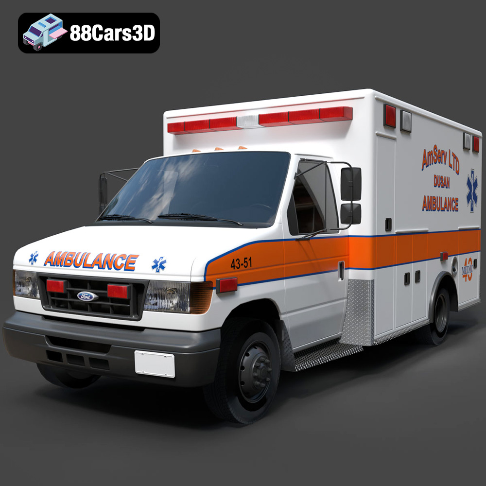
Ford Ambulance AmServ LTD Dusan-002 3D Model
Texture: Yes
Material: Yes
Download the Ford Ambulance AmServ LTD Dusan-002 3D Model featuring a high-detail exterior and interior, realistic textures, and emergency lighting. Includes .blend, .fbx, .obj, .glb, .stl, .ply, .unreal, and .max formats for rendering, simulation, and game development.
Price: $19.99
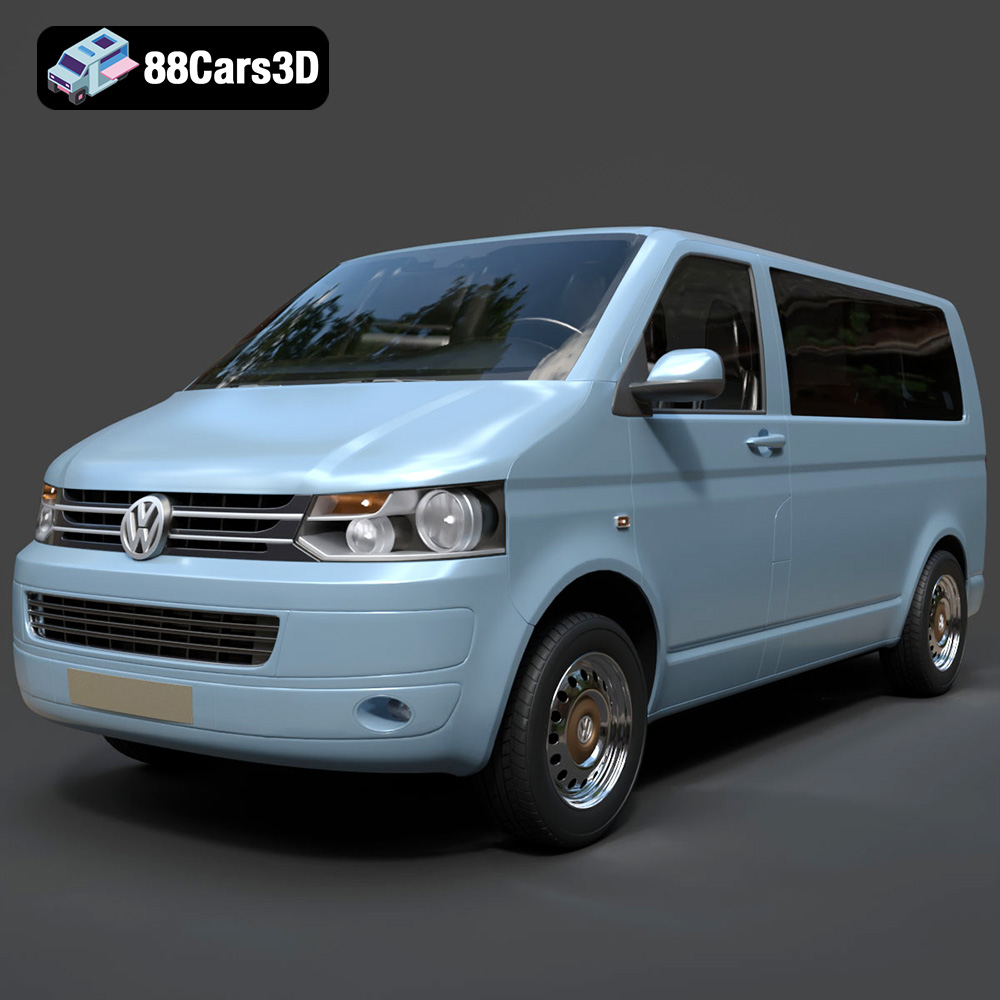
Volkswagen Transporter T5 FL 2010 3D Model
Texture: Yes
Material: Yes
Download the Volkswagen Transporter T5 FL 2010 3D Model featuring clean geometry, realistic detailing, and a fully modeled interior. Includes .blend, .fbx, .obj, .glb, .stl, .ply, .unreal, and .max formats for rendering, simulation, and game development.
Price: $22.99
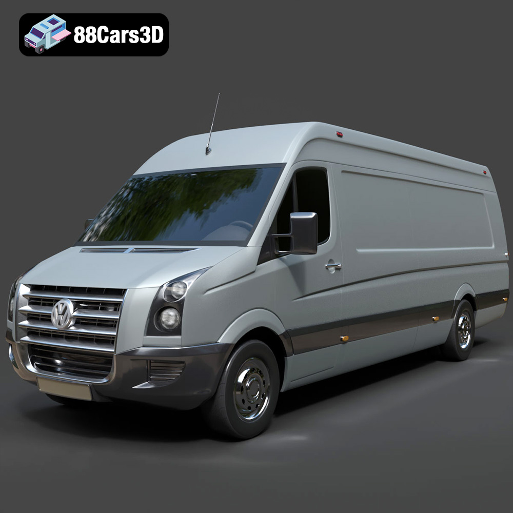
Volkswagen Crafter 2020 3D Model
Texture: Yes
Material: Yes
Download the Volkswagen Crafter 2020 3D Model featuring clean geometry, realistic detailing, and a fully modeled interior. Includes .blend, .fbx, .obj, .glb, .stl, .ply, .unreal, and .max formats for rendering, simulation, and game development.
Price: $22.99
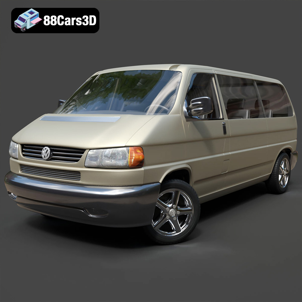
Volkswagen Caravelle 2020 3D Model
Texture: Yes
Material: Yes
Download the Volkswagen Caravelle 3D Model featuring a detailed exterior, functional interior, and optimized topology. Includes .blend, .fbx, .obj, .glb, .stl, .ply, .unreal, and .max formats for rendering, simulation, and game development.
Price: $23.99
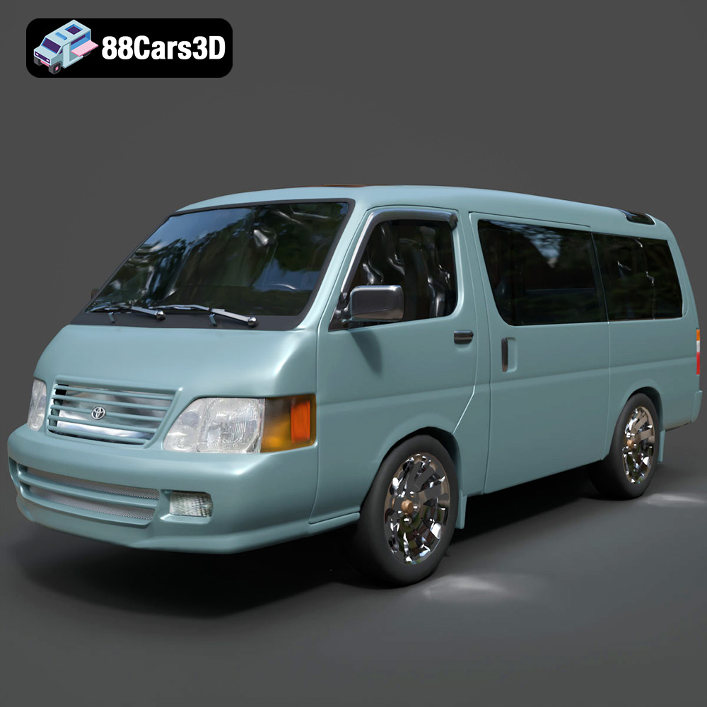
Toyota Hiace 3D Model
Texture: Yes
Material: Yes
Download the Toyota Hiace 3D Model featuring versatile design and detailed exterior. Includes .blend, .fbx, .obj, .glb, .stl, .ply, .unreal, and .max formats for rendering, simulation, and game development.
Price: $21.99
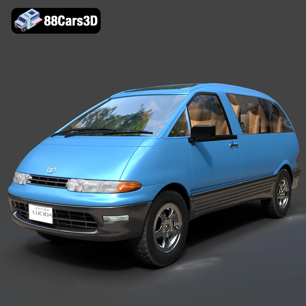
Toyota Estima Lucida 3D Model
Texture: Yes
Material: Yes
Download the Toyota Estima Lucida 3D Model featuring its iconic compact MPV design, versatile interior, and accurate exterior details. Includes .blend, .fbx, .obj, .glb, .stl, .ply, .unreal, and .max formats for rendering, simulation, and game development.
Price: $24.99

Toyota Alphard 3D Model
Texture: Yes
Material: Yes
Download the Toyota Alphard 3D Model featuring a detailed luxury minivan design with an accurate exterior and interior. Includes .blend, .fbx, .obj, .glb, .stl, .ply, .unreal, and .max formats for rendering, simulation, and game development.
Price: $21.99
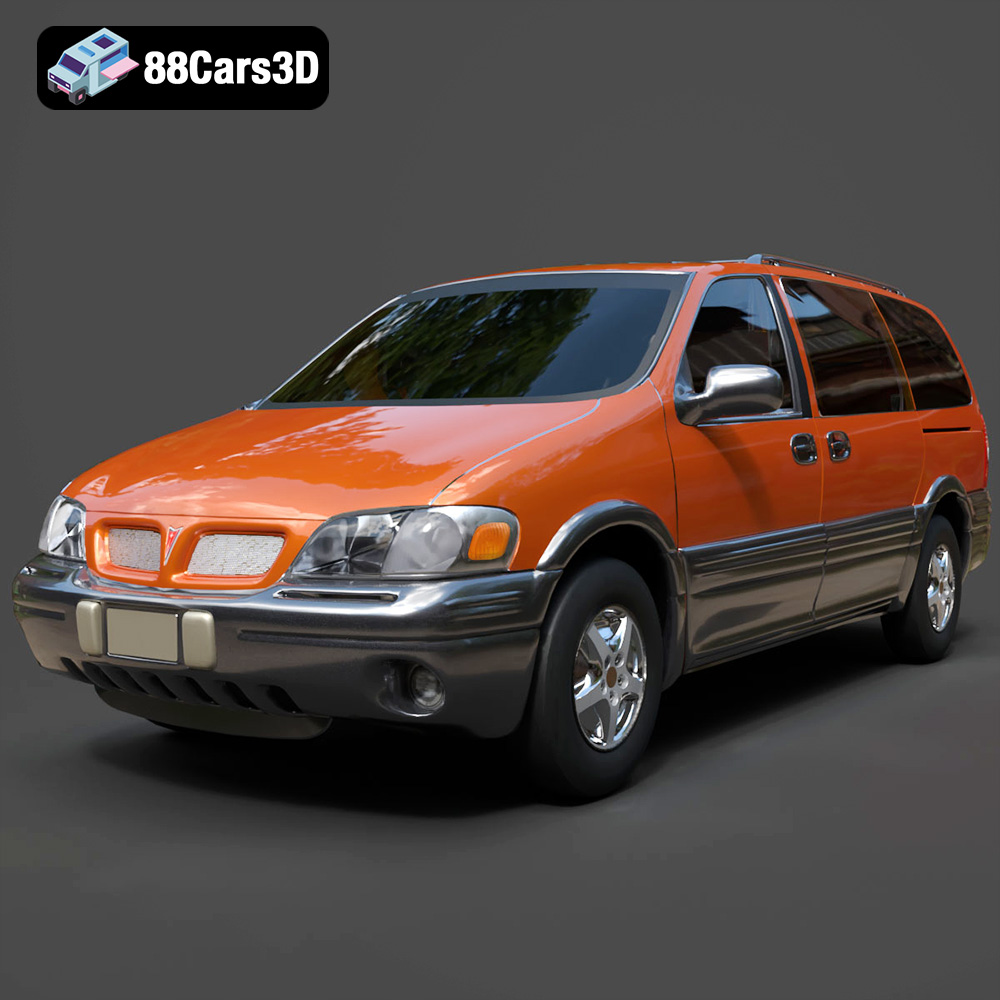
Pontiac Montana 1998 3D Model
Texture: Yes
Material: Yes
Download the Pontiac Montana 1998 3D Model featuring a detailed exterior, functional interior, and optimized mesh. Includes .blend, .fbx, .obj, .glb, .stl, .ply, .unreal, and .max formats for rendering, simulation, and game development.
Price: $21.99
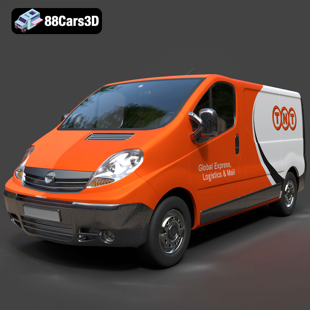
Opel Vivaro 3D Model
Texture: Yes
Material: Yes
Download the Opel Vivaro 3D Model featuring a versatile commercial van design with balanced detailing. Includes .blend, .fbx, .obj, .glb, .stl, .ply, .unreal, and .max formats for rendering, simulation, and game development.
Price: $21.99
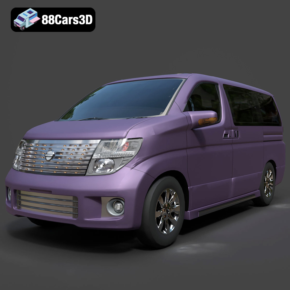
Nissan Elgrand 3D Model
Texture: Yes
Material: Yes
Download the Nissan Elgrand 3D Model featuring a versatile minivan design. Includes .blend, .fbx, .obj, .glb, .stl, .ply, .unreal, and .max formats for rendering, simulation, and game development.
Price: $21.99
