Get 20% OFF All Premium 3D & STL Models!
“`html
The world of 3D printing offers incredible possibilities, from rapid prototyping to creating intricate models like the stunning printable car models available on platforms like 88cars3d.com. However, the journey from downloading an STL file to holding a perfect print isn’t always seamless. STL files, while the industry standard, can sometimes be riddled with imperfections – non-manifold geometry, flipped normals, holes, and intersecting faces – all of which can lead to print failures. Luckily, Blender, a powerful and free open-source 3D creation suite, provides a robust toolset for cleaning up and preparing STL files for a successful print. This comprehensive guide will walk you through the process of identifying and fixing common STL issues in Blender, ensuring your 3D prints come out exactly as intended. We’ll cover everything from importing and inspecting your model to applying modifiers and exporting a clean, print-ready STL file.
In this guide, you’ll learn:
The first step is to import your STL file into Blender. Navigate to File > Import > STL (.stl) and select your file. Once imported, you’ll likely see the model in the viewport. However, simply looking at the model isn’t enough to determine its printability. We need to inspect the mesh for errors that may not be immediately visible.
Blender offers several overlays that are crucial for analyzing mesh quality. In the viewport’s top right corner, click the “Overlays” dropdown menu. Enable the following options:
Blender’s “Mesh Analysis” tool provides a more detailed examination of your model’s geometry. Switch to Edit Mode by pressing Tab. Then, in the top menu, go to Mesh > Clean Up > Make Manifold. While this tool can automatically fix some issues, it’s essential to understand what constitutes a “manifold” mesh. A manifold mesh is a closed, continuous surface without any holes, self-intersections, or edges that are shared by more than two faces. Non-manifold geometry is a common source of 3D printing problems, leading to slicing errors and failed prints.
If the *Make Manifold* tool does not resolve all issues, navigate to Select > Select All by Trait > Non Manifold. This will highlight all the problematic areas of your mesh, making them easier to identify and fix manually.
Once you’ve identified areas with flipped normals or holes, you’ll need to correct them. These imperfections can cause significant issues during slicing, potentially leading to incomplete or deformed prints.
If you’ve identified faces with flipped normals (colored red in the “Face Orientation” overlay), select those faces in Edit Mode. You can do this manually or by using the selection tools. Once selected, press Alt+N to open the “Normals” menu and choose Flip. This will reverse the direction of the normals, turning the red faces blue and ensuring they point outwards. Alternatively, choose Recalculate Outside from the same menu. This option attempts to automatically determine the correct normal direction based on the surrounding faces.
Important Tip: Sometimes, a single flipped normal can cause a chain reaction, flipping the normals of adjacent faces. After flipping normals, re-enable the “Face Orientation” overlay to ensure that the issue is fully resolved and that no new flipped normals have appeared.
Holes in the mesh are another common issue that can prevent successful 3D printing. To fill a hole, switch to Edit Mode and select the boundary edges of the hole. You can do this by holding Alt and clicking on an edge. This will select the entire loop of connected edges. Once the boundary edges are selected, press F to fill the hole with a new face. If the hole is complex, you may need to fill it in multiple steps, creating smaller faces to maintain good geometry.
For more complex holes, the Bridge Edge Loops tool can be useful. Select two opposing edge loops and go to Edge > Bridge Edge Loops. This will create a series of faces connecting the two loops, effectively filling the gap. Adjust the settings of the Bridge Edge Loops tool, such as the number of cuts and smoothness, to achieve the desired result.
Sometimes, even after fixing flipped normals and holes, the overall geometry of the STL file may be uneven or contain excessive triangles, especially after boolean operations or complex modeling. Remeshing can help to create a more uniform and printable mesh.
The Remesh modifier is a powerful tool for rebuilding the mesh with a more consistent topology. In Object Mode, select your object and go to the Modifiers tab in the Properties panel (the wrench icon). Click “Add Modifier” and choose “Remesh.” The Remesh modifier offers several modes:
After applying the Remesh modifier, it’s crucial to apply it by clicking the “Apply” button in the modifier panel. Before applying, make sure the new geometry preserves the details of your model. You may need to experiment with different Voxel Sizes to find the optimal balance between detail and polygon count. A good starting point is to gradually decrease the Voxel Size until the desired level of detail is achieved.
Remeshing can significantly increase the polygon count of your model. This can lead to larger file sizes and potentially slower slicing times. However, a well-remeshed mesh is often easier to print and can result in a smoother surface finish. After remeshing, it’s always a good idea to check the “Statistics” overlay again to assess the number of vertices, edges, and faces.
While a high level of detail is desirable, excessive polygon counts can be detrimental to 3D printing. Large STL files take longer to slice, consume more memory, and can even cause slicer software to crash. The Decimate modifier provides a way to reduce the polygon count without significantly sacrificing the overall shape of your model. This is especially useful when downloading models from marketplaces such as 88cars3d.com, where models are often highly detailed.
In Object Mode, select your object and add a “Decimate” modifier. The Decimate modifier offers several methods for reducing the polygon count:
Start by using the “Ratio” method and gradually decrease the ratio until you achieve a balance between polygon count and detail preservation. Monitor the appearance of your model closely and stop reducing the ratio when you start to notice significant loss of detail. It is also possible to apply more than one Decimate modifier, each with a slightly different set of parameters. This can give you more control over the decimation process.
To minimize detail loss during decimation, consider the following tips:
After cleaning and optimizing your STL file, the final step is to prepare it for export and consider its print orientation. Print orientation can significantly impact print time, support requirements, and the overall quality of your print.
Before exporting, ensure that you have applied all modifiers by clicking the “Apply” button in each modifier panel. Once applied, go to File > Export > STL (.stl). In the export settings, pay attention to the following:
The print orientation is the position of your model on the 3D printer’s build plate. A well-chosen print orientation can minimize support requirements, reduce print time, and improve surface finish. Consider the following factors when determining the optimal print orientation:
Before exporting, rotate your model in Blender to match the desired print orientation. This will ensure that the model is correctly positioned in your slicer software. For automotive models, printing with the wheels down often results in the best bed adhesion and minimizes support requirements. Platforms like 88cars3d.com offer print-ready STL files, but even these can benefit from optimizing the orientation for your specific printer and desired results.
Even with a clean STL file, printing issues can still arise. Understanding common problems and knowing how to troubleshoot them is crucial for achieving successful prints. This section covers some of the most frequently encountered issues and their solutions.
Poor bed adhesion is a common problem that can cause prints to warp or detach from the build plate. Here are some common causes and solutions:
Warping occurs when the corners of the print lift off the build plate due to uneven cooling. Here are some common causes and solutions:
Stringing and blobs are caused by excessive material extrusion during travel moves. Here are some common causes and solutions:
Choosing the right material and configuring your printer settings correctly are essential for achieving high-quality 3D prints. Different materials have different properties and require specific printer settings.
Here are some of the most common 3D printing materials and their properties:
Here are some of the most important printer settings to consider:
Cleaning up STL files in Blender is an essential skill for any 3D printing enthusiast. By understanding the common issues that can arise and knowing how to fix them, you can significantly improve the quality and success rate of your prints. From inspecting and repairing the mesh to optimizing the polygon count and choosing the right print orientation, each step in the process contributes to a better final product. Whether you’re printing intricate car models from 88cars3d.com or prototyping your own designs, mastering these techniques will empower you to bring your ideas to life with confidence. Remember to always double-check your work, experiment with different settings, and don’t be afraid to iterate until you achieve the desired results.
Your next steps should be:
“`
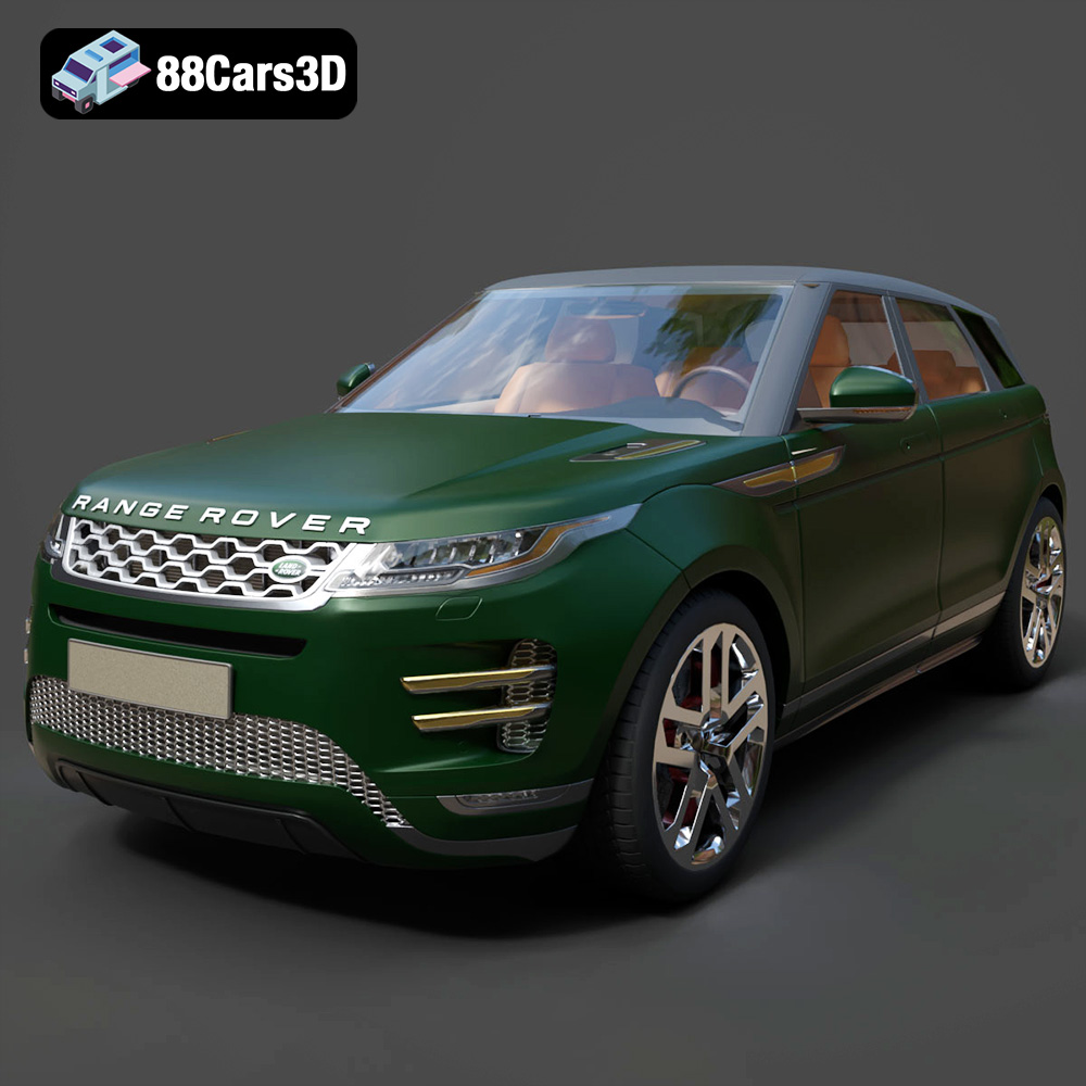
Texture: Yes | Material: Yes
Download the highly detailed, game-ready Range Rover Evoque R-Dynamic 2019 3D Model. Features flush deployable door handles, Matrix LED headlights, and R-Dynamic styling. Includes .blend, .fbx, .obj, .glb, .stl, .ply, .unreal, and .max formats for game development, AR/VR, and rendering.
Price: $19.99

Texture: Yes | Material: Yes
Download the highly detailed, game-ready Ford Mustang Mach 40 3D Model. Features aggressive custom widebody styling, a mid-mounted V8 engine, and classic retro-futuristic design. Includes .blend, .fbx, .obj, .glb, .stl, .ply, .unreal, and .max formats for game development, AR/VR, and rendering.
Price: $19.99
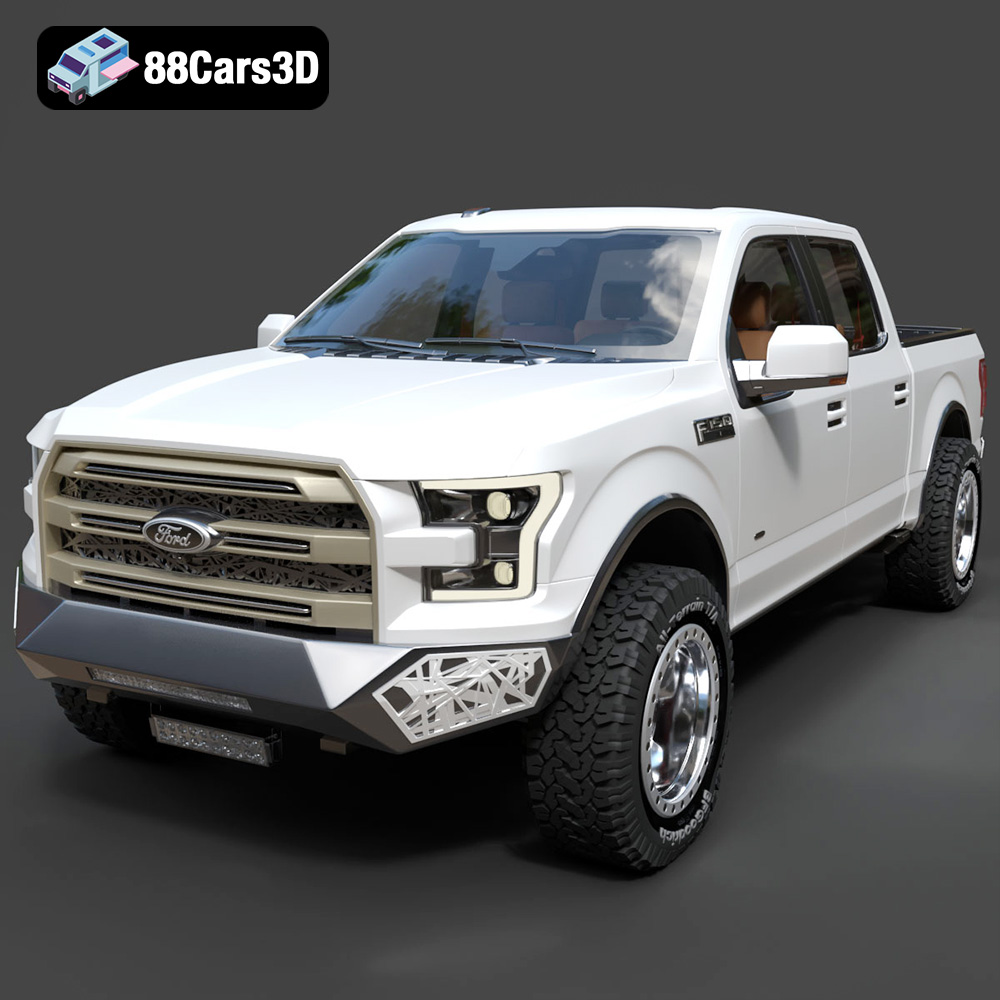
Texture: Yes | Material: Yes
Download the highly detailed, game-ready Ford F150 Raptor With Tuning From ARE 3D Model. Features custom ARE tuning accessories, aggressive off-road suspension, and rugged beadlock wheels. Includes .blend, .fbx, .obj, .glb, .stl, .ply, .unreal, and .max formats for game development, AR/VR, and rendering.
Price: $19.99

Texture: Yes | Material: Yes
Download the highly detailed, game-ready Mercedes-Benz AMG GLE 63 2021 3D Model. Features the iconic Panamericana grille, aggressive aerodynamic body styling, and a meticulously detailed luxurious interior. Includes .blend, .fbx, .obj, .glb, .stl, .ply, .unreal, and .max formats for game development, AR/VR, and rendering.
Price: $19.99
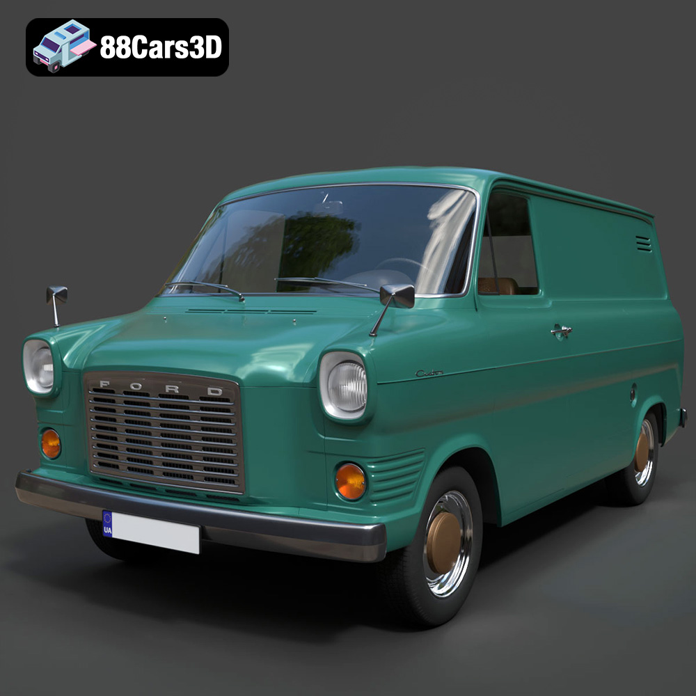
Texture: Yes | Material: Yes
Download the highly detailed, game-ready Ford Transit Mk1 Panel Van 1965 3D Model. Features iconic flat-front styling, vintage steel wheels, and a period-correct cargo bay. Includes .blend, .fbx, .obj, .glb, .stl, .ply, .unreal, and .max formats for game development, AR/VR, and rendering.
Price: $19.99

Texture: Yes | Material: Yes
Download the highly detailed, game-ready BMW X3 2024 3D Model. Features the iconic kidney grille, dynamic SUV proportions, and precise lighting elements. Includes .blend, .fbx, .obj, .glb, .stl, .ply, .unreal, and .max formats for game development, AR/VR, and rendering.
Price: $19.99

Texture: Yes | Material: Yes
Download the highly detailed, game-ready Tesla Model S Plaid 2021 3D Model. Features sleek aerodynamic styling, signature LED lighting, and the revolutionary Yoke steering interior. Includes .blend, .fbx, .obj, .glb, .stl, .ply, .unreal, and .max formats for game development, AR/VR, and rendering.
Price: $19.99

Texture: Yes | Material: Yes
Download the highly detailed, game-ready Rolls-Royce Ghost EWB 2018 3D Model. Features the iconic Pantheon grille, elongated luxury chassis, and elegant exterior lines. Includes .blend, .fbx, .obj, .glb, .stl, .ply, .unreal, and .max formats for game development, AR/VR, and rendering.
Price: $19.99
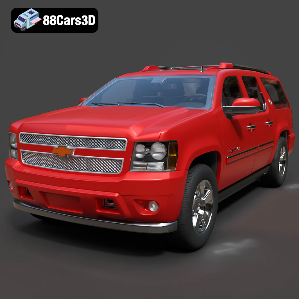
Texture: Yes | Material: Yes
Download the highly detailed, game-ready Chevrolet Suburban 75th Diamond 3D Model. Features the iconic Diamond Edition styling, detailed interior, and accurate full-size SUV proportions. Includes .blend, .fbx, .obj, .glb, .stl, .ply, .unreal, and .max formats for game development, AR/VR, and rendering.
Price: $19.99

Texture: Yes | Material: Yes
Download the highly detailed, game-ready Lamborghini Terzo Millenio 2017 3D Model. Features glowing Y-shaped LED signatures, extreme aerodynamic channels, and an aggressive hypercar stance. Includes .blend, .fbx, .obj, .glb, .stl, .ply, .unreal, and .max formats for game development, AR/VR, and rendering.
Price: $19.99

