Get 20% OFF All Premium 3D & STL Models!
“`html
3D printing has revolutionized the way we prototype, manufacture, and even enjoy hobbies. For automotive enthusiasts and model makers, platforms like 88cars3d.com offer an incredible selection of 3D printable car models in STL format. However, before you hit that “print” button, ensuring your STL file is error-free is crucial for a successful outcome. A flawed STL can lead to print failures, poor surface quality, and wasted filament or resin. This comprehensive guide will equip you with the knowledge and tools to identify and fix common STL file errors, ensuring your 3D prints are as stunning as the digital designs themselves. We’ll delve into mesh topology, repair strategies, software-specific techniques, and much more, enabling you to master the art of STL file preparation.
STL (Stereolithography) files are the workhorse of 3D printing. They represent the surface geometry of a 3D model as a collection of triangles. Errors in this triangular mesh can manifest in various ways during the printing process. Gaps in the mesh can lead to missing sections in your print, while self-intersecting triangles can cause slicing software to generate incorrect toolpaths. Non-manifold geometry, where edges are shared by more than two triangles, is another common culprit that can confuse slicers and result in print failures. Addressing these issues before printing is not just about aesthetics; it’s about ensuring structural integrity, dimensional accuracy, and overall print success.
In this post, you’ll learn how to:
At its core, an STL file is a simple text (or binary) format that describes the surface of a 3D object using a collection of triangles. Each triangle is defined by its three vertices (corners) and a normal vector, which indicates the direction the triangle is facing. The way these triangles are connected defines the mesh topology, which is crucial for the integrity of the model. Understanding these fundamentals is essential for identifying and rectifying errors.
The STL format relies heavily on the concept of tessellation, which is the process of covering a surface with polygons (in this case, triangles). Each triangle is referred to as a “facet.” The density of the triangle mesh directly impacts the level of detail in the 3D print. A higher density (more triangles) results in a smoother surface but also increases the file size and processing time. Finding the right balance between detail and efficiency is key. For example, a car model downloaded from 88cars3d.com may have a high triangle count to capture intricate details, but you might need to simplify it for faster printing or if your printer has limitations.
One of the most critical concepts in STL file preparation is manifold geometry. A manifold mesh is one where every edge is shared by exactly two triangles. Think of it like a closed container – there are no holes or loose edges. Non-manifold geometry, on the other hand, violates this rule. Edges might be shared by more than two triangles, or not shared at all (open edges). These non-manifold errors can cause significant problems during slicing and printing. Imagine trying to fill a container with a hole in it – the slicer will struggle to define the “inside” and “outside” of the model.
Several types of errors can plague STL files, including:
These errors can arise from various sources, including issues during the CAD modeling process, file conversion errors, or data corruption.
Fortunately, numerous software tools are available to help you diagnose and fix STL file errors. These tools range from free and open-source options to professional-grade software suites. The best choice for you will depend on your budget, technical expertise, and the complexity of the models you’re working with.
Meshmixer, a free software from Autodesk, is a favorite among 3D printing enthusiasts due to its user-friendly interface and powerful mesh editing capabilities. It offers a range of tools specifically designed for repairing STL files, including automated error detection and correction. To repair an STL in Meshmixer:
Meshmixer’s “Make Solid” tool is particularly useful for creating watertight meshes, which are essential for 3D printing. It intelligently fills gaps and creates a closed surface from the existing geometry.
Netfabb, another Autodesk product, is a more advanced software solution used by professionals in the additive manufacturing industry. It offers a comprehensive suite of tools for STL file repair, mesh optimization, and build preparation. While Netfabb is a paid software, it provides a level of control and precision that is unmatched by free alternatives.
Key features of Netfabb for STL repair include:
Netfabb is particularly valuable for complex models with intricate details, where manual intervention may be required to ensure a successful repair.
Blender is a free and open-source 3D creation suite that can also be used for STL file repair, although it requires a bit more technical knowledge. While not specifically designed for STL repair, Blender’s powerful modeling tools can be used to fix a wide range of errors. For example, you can use Blender’s “Edit Mode” to manually close gaps, merge vertices, and correct inverted normals. The “Remesh” modifier can be used to rebuild the mesh with a more uniform topology, which can help to resolve complex errors. Be sure to check the “Non-Manifold” selection under Select -> Select All by Trait -> Non Manifold to highlight areas that need attention.
Using Blender for STL repair offers a high degree of control but requires a steeper learning curve compared to Meshmixer or Netfabb. However, if you’re already familiar with Blender, it can be a powerful tool for preparing your models for 3D printing.
Once your STL file is repaired, the next crucial step is slicing – converting the 3D model into a set of instructions that the 3D printer can understand. Slicing software, such as Cura, PrusaSlicer, and Simplify3D, divides the model into thin horizontal layers and generates a toolpath for the printer to follow. The slicing parameters you choose can significantly impact the print quality, strength, and overall success of your print.
Layer height is one of the most fundamental slicing parameters. It determines the thickness of each layer in the printed object. A smaller layer height results in a smoother surface finish and finer details, but it also increases the print time and material consumption. A larger layer height, conversely, results in a faster print but with a coarser surface finish. For example, when printing a detailed car model from 88cars3d.com, you might choose a smaller layer height (e.g., 0.1mm) to capture the intricate curves and features. For larger, less detailed parts, a larger layer height (e.g., 0.2mm or 0.3mm) might be sufficient.
Infill refers to the internal structure of the 3D printed object. It provides strength and support while minimizing material usage. Infill density is the percentage of the object’s interior that is filled with material. A higher infill density results in a stronger, heavier object, while a lower infill density results in a weaker, lighter object. The infill pattern also plays a role in the object’s strength and print time. Common infill patterns include:
For most applications, an infill density of 15-25% is sufficient. For parts that need to withstand high loads, you may need to increase the infill density to 50% or higher.
Print speed and temperature are crucial parameters that affect the adhesion between layers and the overall quality of the print. The optimal print speed and temperature will depend on the material you’re using and the capabilities of your 3D printer. For PLA, a typical print speed is 40-60mm/s and a nozzle temperature of 200-220°C. For ABS, a typical print speed is 50-80mm/s and a nozzle temperature of 230-250°C. It’s essential to consult the manufacturer’s recommendations for the specific material you’re using.
Experimentation is key to finding the optimal settings for your specific setup.
Support structures are temporary scaffolding used to support overhanging features during 3D printing. Without supports, these features would collapse under their own weight. Generating and removing support structures is a critical aspect of the 3D printing process, and choosing the right support settings can significantly impact the final print quality.
There are several types of support structures, each with its own advantages and disadvantages:
The choice of support type will depend on the geometry of the model and the specific requirements of the print. For example, tree supports are often preferred for models with organic shapes and delicate features.
Slicing software offers a variety of settings for controlling the generation of support structures, including:
Experimenting with these settings is essential for optimizing the support structures for your specific model and printer. A general recommendation is to start with a support overhang angle of 45 degrees and adjust as needed.
Removing support structures can be a delicate process, as it’s important to avoid damaging the printed object. Here are some common support removal techniques:
The best technique will depend on the type of support material used and the complexity of the model. For delicate parts, it’s often best to use dissolvable or breakaway supports to minimize the risk of damage. For PLA, supports can often be removed by hand. ABS may require the use of tools. Careful and slow removal is always advised.
Choosing the right material and ensuring your printer is properly calibrated are essential for achieving optimal results in 3D printing. The material properties affect the strength, flexibility, and appearance of the printed object, while printer calibration ensures dimensional accuracy and print reliability.
FDM (Fused Deposition Modeling) and resin printing are the two most common 3D printing technologies, and they use vastly different materials. FDM printers use filaments made of thermoplastics, such as PLA, ABS, PETG, and nylon. Resin printers use liquid resins that are cured by UV light.
The choice of material will depend on the specific requirements of your project. For printable car models from marketplaces such as 88cars3d.com, PLA or PETG are often good choices for FDM printing, while various resins are suitable for resin printing, depending on the desired properties.
Proper printer calibration is crucial for ensuring dimensional accuracy and print reliability. Here are some key calibration steps:
Regular printer maintenance is also important for preventing problems and ensuring consistent print quality. This includes cleaning the nozzle, lubricating moving parts, and checking for wear and tear.
Even with proper STL file preparation and printer calibration, you may still encounter printing issues. Here are some common problems and their solutions:
By systematically troubleshooting these issues, you can improve the reliability and quality of your 3D prints.
Fixing STL file errors before 3D printing is a critical step in achieving successful and high-quality results. By understanding the structure of STL files, using appropriate repair tools, and optimizing slicing parameters, you can minimize the risk of print failures and maximize the potential of your 3D printer. Remember to choose the right material for your project and to calibrate your printer properly. Whether you’re printing intricate car models from platforms like 88cars3d.com or functional prototypes, mastering STL file preparation will empower you to create stunning and reliable 3D prints.
By continuously learning and refining your skills, you can unlock the full potential of 3D printing and bring your creative ideas to life.
“`

Texture: Yes | Material: Yes
Download the highly detailed, game-ready Mercedes Benz CLS500 3D Model. Features sleek four-door coupe styling, detailed alloy wheels, and a premium interior. Includes .blend, .fbx, .obj, .glb, .stl, .ply, .unreal, and .max formats for game development, AR/VR, and rendering.
Price: $19.99

Texture: Yes | Material: Yes
Download the highly detailed, game-ready Ducati 1299 Panigale S 2017 3D Model. Features signature aerodynamic fairings, detailed Superquadro engine components, and aggressive Italian styling. Includes .blend, .fbx, .obj, .glb, .stl, .ply, .unreal, and .max formats for game development, AR/VR, and rendering.
Price: $19.99
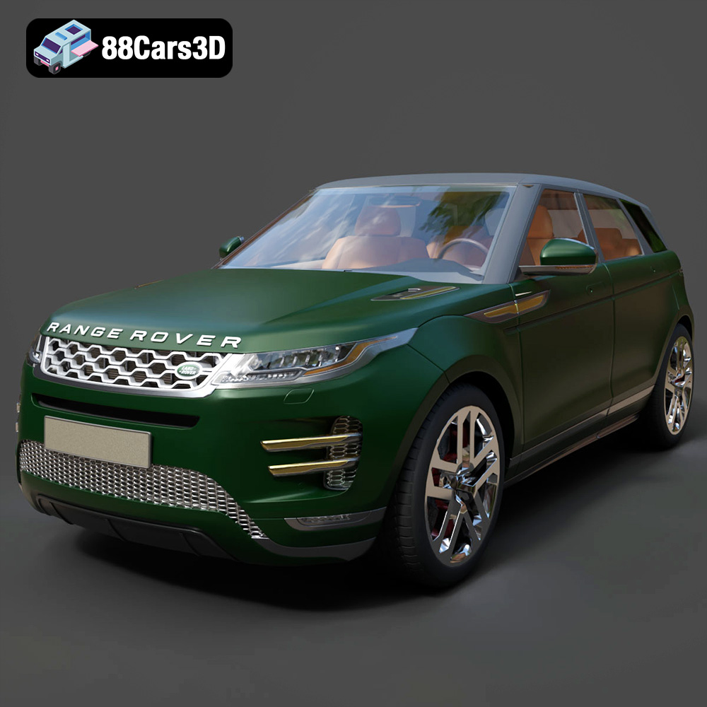
Texture: Yes | Material: Yes
Download the highly detailed, game-ready Range Rover Evoque R-Dynamic 2019 3D Model. Features flush deployable door handles, Matrix LED headlights, and R-Dynamic styling. Includes .blend, .fbx, .obj, .glb, .stl, .ply, .unreal, and .max formats for game development, AR/VR, and rendering.
Price: $19.99

Texture: Yes | Material: Yes
Download the highly detailed, game-ready Ford Mustang Mach 40 3D Model. Features aggressive custom widebody styling, a mid-mounted V8 engine, and classic retro-futuristic design. Includes .blend, .fbx, .obj, .glb, .stl, .ply, .unreal, and .max formats for game development, AR/VR, and rendering.
Price: $19.99
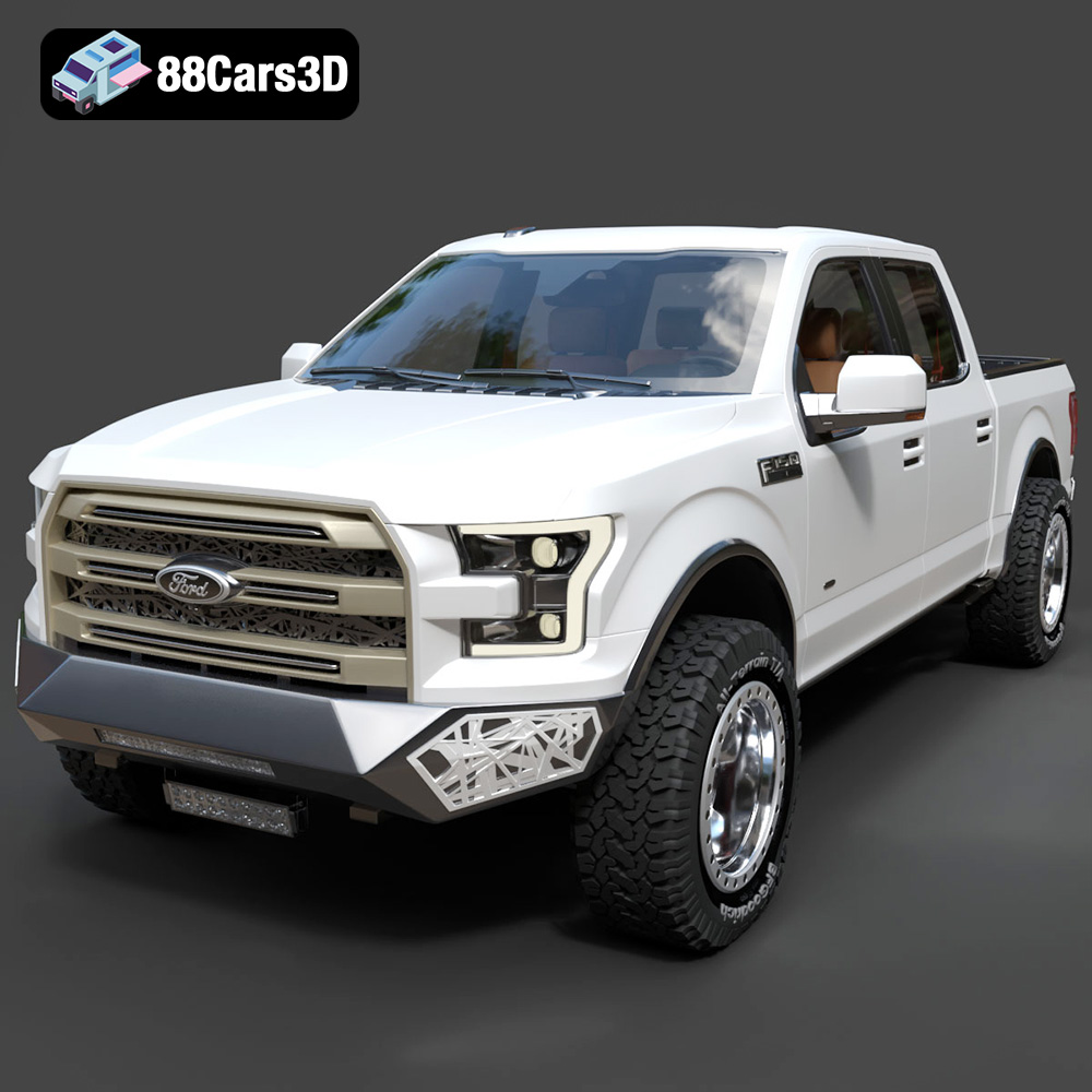
Texture: Yes | Material: Yes
Download the highly detailed, game-ready Ford F150 Raptor With Tuning From ARE 3D Model. Features custom ARE tuning accessories, aggressive off-road suspension, and rugged beadlock wheels. Includes .blend, .fbx, .obj, .glb, .stl, .ply, .unreal, and .max formats for game development, AR/VR, and rendering.
Price: $19.99

Texture: Yes | Material: Yes
Download the highly detailed, game-ready Mercedes-Benz AMG GLE 63 2021 3D Model. Features the iconic Panamericana grille, aggressive aerodynamic body styling, and a meticulously detailed luxurious interior. Includes .blend, .fbx, .obj, .glb, .stl, .ply, .unreal, and .max formats for game development, AR/VR, and rendering.
Price: $19.99
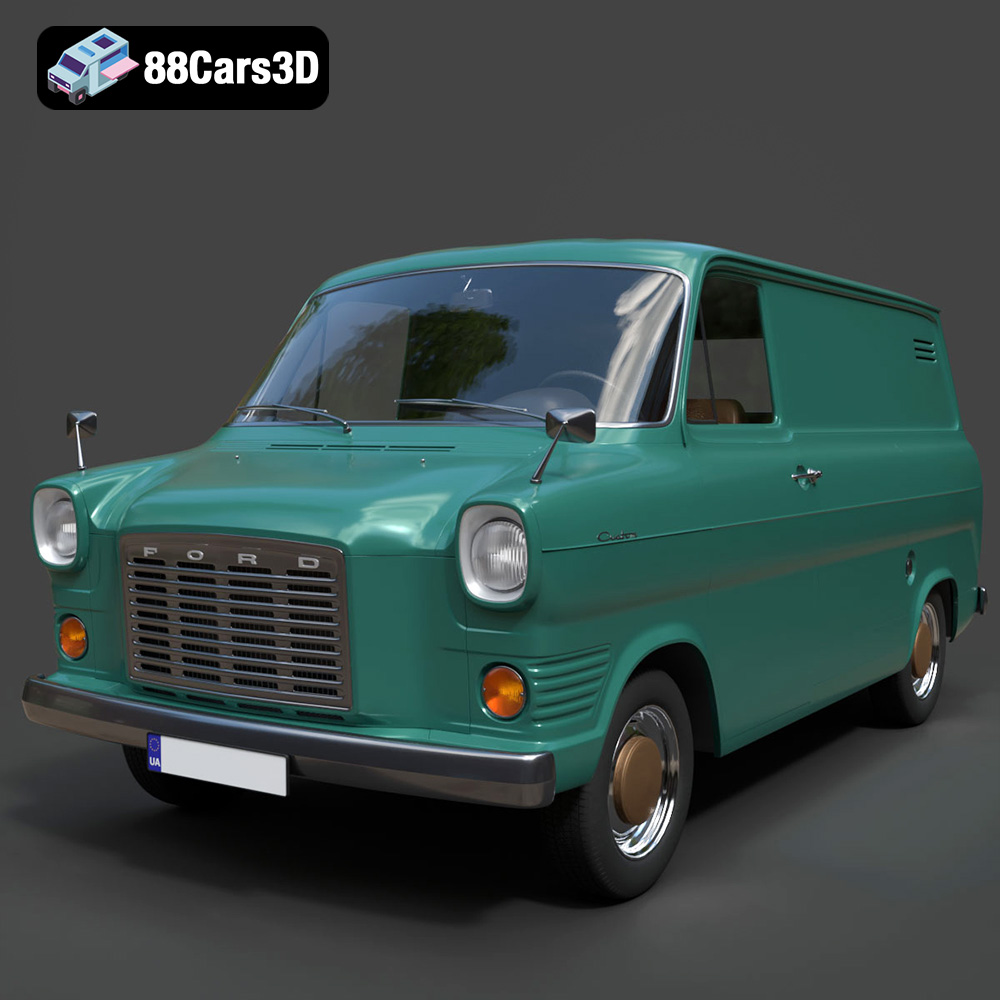
Texture: Yes | Material: Yes
Download the highly detailed, game-ready Ford Transit Mk1 Panel Van 1965 3D Model. Features iconic flat-front styling, vintage steel wheels, and a period-correct cargo bay. Includes .blend, .fbx, .obj, .glb, .stl, .ply, .unreal, and .max formats for game development, AR/VR, and rendering.
Price: $19.99

Texture: Yes | Material: Yes
Download the highly detailed, game-ready BMW X3 2024 3D Model. Features the iconic kidney grille, dynamic SUV proportions, and precise lighting elements. Includes .blend, .fbx, .obj, .glb, .stl, .ply, .unreal, and .max formats for game development, AR/VR, and rendering.
Price: $19.99

Texture: Yes | Material: Yes
Download the highly detailed, game-ready Tesla Model S Plaid 2021 3D Model. Features sleek aerodynamic styling, signature LED lighting, and the revolutionary Yoke steering interior. Includes .blend, .fbx, .obj, .glb, .stl, .ply, .unreal, and .max formats for game development, AR/VR, and rendering.
Price: $19.99

Texture: Yes | Material: Yes
Download the highly detailed, game-ready Rolls-Royce Ghost EWB 2018 3D Model. Features the iconic Pantheon grille, elongated luxury chassis, and elegant exterior lines. Includes .blend, .fbx, .obj, .glb, .stl, .ply, .unreal, and .max formats for game development, AR/VR, and rendering.
Price: $19.99

