
The allure of automotive design goes beyond the screen. For 3D artists, designers, and enthusiasts alike, there’s a unique satisfaction in transforming a meticulously crafted digital car model into a tangible, physical object. Whether for prototyping, display, educational purposes, or even as high-fidelity game asset miniatures, 3D printing offers an incredible bridge between the virtual and real worlds. However, this journey from Blender to print bed isn’t always a straightforward one. A beautiful render-ready model, with its intricate details and optimized polygon count for visual fidelity, often harbors hidden complexities that make it unsuitable for direct 3D printing.
This comprehensive guide from 88cars3d.com will demystify the process, equipping you with the knowledge and techniques required to prepare your Blender car models for successful 3D printing. We’ll delve deep into critical aspects such as mesh integrity, topology, scaling, and file format considerations, ensuring your automotive masterpieces translate flawlessly into the physical realm. From ensuring watertight geometry to optimizing for material consumption and print strength, we’ll cover the essential steps that turn potential printing failures into triumphant successes. Prepare to elevate your workflow and unlock the full potential of your 3D car models.
Before we even touch a modifier in Blender, it’s crucial to grasp the fundamental requirements of 3D printing. Unlike rendering, which forgives open edges and overlapping geometry, 3D printing demands a physically coherent, “watertight” mesh. Imagine trying to fill a bucket with water if it has holes; the same principle applies to 3D printing. Your model must be a solid, closed volume, free from internal faces, intersecting geometry, or unjoined vertices. This concept is often referred to as a “manifold” mesh, meaning every edge is connected to exactly two faces, forming a continuous surface.
For car models, which often feature complex curves, intricate details like grilles, spoilers, and mirrors, achieving manifold geometry can be a significant challenge. Blender provides a robust set of tools to tackle this. Key principles include ensuring sufficient wall thickness—thin elements tend to break or not print at all—and understanding how overhangs will be supported during the printing process. Different 3D printing technologies have varying tolerances for these factors. FDM (Fused Deposition Modeling) printers, for example, typically require thicker walls (e.g., 0.8mm minimum) and often struggle with steep overhangs without support structures, while SLA (Stereolithography) resin printers can achieve finer details and smoother surfaces but might require even more careful hollowing and support placement.
The bedrock of a successful 3D print is a model that is truly solid. Watertightness means your model has no holes, gaps, or unclosed surfaces. Any non-manifold edges or vertices will confuse the slicer software, leading to errors, incomplete prints, or an inability to slice the model at all. This is particularly relevant for intricate car components like wheel spokes or exhaust pipes. Wall thickness is another critical factor. While your model might look solid on screen, if its walls are too thin, it won’t be physically robust enough to print or handle. Most FDM printers require a minimum wall thickness of around 0.8mm to 1.5mm, depending on the material and nozzle size, while SLA printers can go as low as 0.3mm to 0.5mm for fine details. Always check the specific recommendations for your printer and material. Lastly, overhangs are sections of your model that extend outwards without direct support from below. Gravity will cause uncured material (resin) or extruded plastic (filament) to sag. While some printers can handle angles up to 45-60 degrees without supports, steeper angles will necessitate generating support structures in your slicer, which can add to print time, material usage, and post-processing effort. Strategic model orientation in Blender can significantly reduce the need for supports.
Blender offers powerful tools to help achieve a solid, printable mesh. The Boolean modifier is invaluable for combining multiple objects into a single, complex shape or for cutting out precise holes. When using Booleans, ensure your source meshes are clean and overlapping properly to avoid geometry issues. Post-Boolean cleanup is often necessary to fix N-gons or non-manifold edges introduced by the operation. Another essential tool is checking for non-manifold geometry. In Edit Mode, you can use the “Select Non Manifold” feature (accessed via Select > Select All by Trait > Non Manifold or searching with F3) to highlight problem areas. These are typically edges connected to more than two faces (internal geometry) or fewer than two faces (holes). Addressing these issues, often by merging vertices, filling faces (F key), or deleting internal geometry, is paramount. For detailed guidance on mesh editing and ensuring manifold geometry, the official Blender 4.4 documentation provides extensive resources on editing meshes and understanding manifoldness.
Even if your car model appears visually complete in Blender, its underlying mesh topology plays a crucial role in its 3D printability. Poor topology—such as internal faces, overlapping geometry, or disconnected mesh islands—can lead to errors in the slicing software, resulting in incomplete prints, surface imperfections, or outright print failure. Automotive models, with their smooth, continuous surfaces and sharp design lines, require particularly clean topology to maintain their aesthetic integrity when printed. While game asset optimization often focuses on polygon reduction and UV mapping, 3D printing preparation prioritizes geometric solidity and structural integrity.
A well-prepared model will have a clean, continuous mesh without any self-intersecting polygons or zero-area faces. These subtle issues, often invisible during rendering, can cause significant problems for slicers attempting to generate toolpaths. The goal is to create a mesh that the slicer can unambiguously interpret as a solid, physical object. This means meticulously checking for and repairing any anomalies that could compromise the model’s structural soundness or lead to printing artifacts. For complex car models, this often involves systematic checks and corrections across the entire mesh, focusing on areas where multiple parts meet or where fine details are present.
Non-manifold geometry is the nemesis of 3D printing. It represents edges or vertices that don’t conform to the “two faces per edge” rule, making it impossible for a 3D printer to interpret the volume of an object. Common culprits include: dangling vertices, disconnected edges, internal faces, and edges connected to more than two faces. In Blender, a powerful tool for identifying these issues is the built-in 3D Print Toolbox addon. Enable it via Edit > Preferences > Add-ons and searching for “3D Print Toolbox.” Once enabled, it appears in the N-panel (sidebar) in the 3D Viewport. This addon provides a suite of checks, including “Check All,” which highlights errors like non-manifold edges, intersections, and zero-area faces. Alternatively, in Edit Mode, you can manually select non-manifold geometry using Select > Select All by Trait > Non Manifold. Once selected, these areas can be repaired by merging vertices (M key), deleting internal faces (X > Faces), or filling holes (F key to create a face between selected edges/vertices). For more complex repairs, retopology tools or remeshing modifiers might be necessary, but always aim for minimal changes to preserve design intent, especially for detailed 3D car models found on platforms like 88cars3d.com.
Once your mesh is manifold, the next crucial step is to ensure adequate wall thickness throughout the entire model. Thin walls are fragile and prone to breaking during printing or post-processing, or they might not even materialize on the print bed. For automotive models, thin elements can include antenna, door handles, spoilers, or intricate grille patterns. Utilize Blender’s measuring tools to verify dimensions. The Solidify Modifier can be a lifesaver here, allowing you to add uniform thickness to open surfaces, effectively creating a shell from a thin mesh. Pay close attention to concave areas and sharp corners, as the Solidify Modifier can sometimes cause self-intersections in these regions; manual cleanup might be required. For delicate features that are inherently thin, consider exaggerating their thickness slightly in Blender to ensure they are robust enough for printing without distorting the overall design. When designing for 3D printing, it’s often better to slightly over-engineer thickness than to risk a failed print. Remember that the minimum printable wall thickness varies significantly with the printing technology and material. FDM typically requires at least 0.8mm, while SLA can handle finer details down to 0.3mm to 0.5mm, but these fine details are more brittle. Always reference your printer and material specifications.
The transition from a virtual model to a physical object involves more than just a solid mesh; it also demands careful consideration of size, print orientation, and the necessity of support structures. An exquisitely detailed 3D car model, whether it’s a render-ready asset or a meticulously crafted prototype, needs to be scaled correctly to meet real-world dimensions or specific print size requirements. Furthermore, the way you orient your model on the build plate can significantly impact print quality, print time, and the amount of support material needed, directly affecting the final result and post-processing effort.
Understanding these factors early in the preparation process can save hours of frustration and wasted material. For complex automotive designs, especially those with numerous overhangs or delicate features, strategic orientation becomes an art form. It’s about finding the balance between minimizing supports, optimizing surface finish on critical areas, and ensuring structural integrity during the print. This section will guide you through correctly scaling your Blender models and making informed decisions about their placement on the print bed to achieve optimal results.
The scale of your 3D car model in Blender must correspond accurately to its desired physical size. Blender operates in a unitless system by default, but you can define scene units (Scene Properties > Units) to Imperial or Metric (meters, millimeters, centimeters). For 3D printing, working in millimeters or centimeters is often most convenient and directly translates to most slicer software. Ensure your model is scaled correctly before exporting. If your car model is designed to be, for example, 1:24 scale, you’ll need to calculate its real-world dimensions and scale it accordingly in Blender. You can use the ‘N’ panel (Transform properties) in Object Mode to check and adjust dimensions. Always apply scale (Object > Apply > Scale or Ctrl+A > Scale) after adjusting the size to avoid issues with modifiers, transformations, or physics simulations in Blender, and to ensure the correct dimensions are passed to the slicer software. Failure to apply scale can lead to unexpected results when importing into slicers, where models might appear minuscule or gargantuan.
The orientation of your car model on the 3D printer’s build plate is one of the most critical decisions affecting print quality, strength, and the amount of necessary support material. Think about the geometry of a car: a long chassis, distinct wheels, often intricate interiors, and potentially thin spoilers. Orienting parts to minimize overhangs is key, as unsupported areas will either deform or require extensive support structures. For FDM printing, aiming to keep features above a 45-degree angle from the vertical without support is a good rule of thumb. For example, printing a car chassis flat on its base might minimize supports for the bottom, but the wheel arches could become massive overhangs. Printing a car on its side or at an angle might reduce overhangs on the body, but could increase support for other features or warp if not properly adhered to the build plate. Consider breaking down complex car models into smaller, easier-to-print components. For instance, print wheels separately from the chassis, and then assemble them. This modular approach, where parts are designed to be joined post-print, can drastically reduce support material and improve surface finish on critical aesthetic areas. For resin (SLA) printing, angling models often helps with support generation and reduces the “peel force” from the FEP film, but this comes at the cost of increased supports and potentially longer print times.
With the core mesh integrity established and optimal scaling and orientation considered, the next phase involves refining your car model for efficient and cost-effective 3D printing. This stage focuses on optimizing the model’s polygon count, reducing material usage, and ensuring a seamless export process. High-detail 3D car models, especially those designed for rendering or cinematic use, often contain a polygon count far exceeding what’s necessary or even manageable for 3D printing, leading to large file sizes and longer processing times in slicer software. Similarly, printing a solid block of material can be wasteful and expensive, particularly for larger models.
This section will guide you through techniques like decimation to intelligently reduce polygon count without sacrificing critical visual detail, and hollowing to conserve material and reduce print time. We’ll also cover the crucial steps for preparing your model for export, ensuring that all transformations are applied, and the mesh is ready for interpretation by slicing software. These advanced preparation steps are vital for optimizing both the printing process and the quality of the final physical automotive model.
While high polygon counts contribute to smooth surfaces in rendering, they can be overkill and even problematic for 3D printing. Excessively dense meshes can lead to extremely large file sizes, slow down your slicer software, or even cause it to crash. The goal is to reduce the polygon count while preserving the crucial details of your automotive design. Blender’s Decimate Modifier is an excellent tool for this task. You can apply it in a few ways:
Always apply the Decimate Modifier non-destructively by keeping it in the modifier stack until you’re satisfied, then apply it before exporting. Be cautious not to decimate too aggressively, as this can lead to loss of detail, especially on intricate grilles, emblems, or sharp body lines of your car model. For objects that will be post-processed (sanded, painted), a slightly lower polygon count might be acceptable, but for highly detailed display models, precision is key. After decimation, always re-check for non-manifold geometry, as the process can sometimes introduce new issues.
Printing a solid car model, especially a large one, can be incredibly expensive in terms of material and take an extensive amount of time. Hollowing is a technique used to create an internal cavity within your model, significantly reducing material consumption and often shortening print times. It’s particularly beneficial for resin printing (SLA/DLP), where resin costs can quickly add up. In Blender, the Solidify Modifier can be used for hollowing. Apply the modifier, ensure “Even Thickness” is enabled, and adjust the “Thickness” value to create the desired shell thickness (e.g., 1.5mm to 2mm for larger FDM prints, 1mm for SLA prints). Crucially, for hollowing to be effective and to prevent uncured resin from getting trapped (in SLA), you must add drainage holes to your model. These are small holes (typically 2-3mm in diameter) placed in inconspicuous areas that allow excess resin to escape or internal support structures to be removed. You can create these by adding a small cylinder, positioning it to intersect the model’s shell, and using a Boolean Difference operation to cut the hole. Ensure at least two drainage holes are present for proper internal air circulation and resin drainage. After hollowing, it’s paramount to perform another manifold check, as the process can sometimes create internal intersections or non-manifold edges if not executed carefully.
Once your Blender car model is meticulously prepared – manifold, appropriately scaled, optimally oriented, and perhaps decimated and hollowed – the final step in Blender is to export it in a format that your 3D printer’s slicer software can understand. This seemingly simple step is critical, as an incorrect file format or improper export settings can undo all your hard work, leading to errors during slicing or failed prints. Different 3D printing workflows and software often prefer specific file types, each with its own advantages and limitations.
Understanding these distinctions and performing the export correctly ensures a smooth transition from your 3D modeling environment to the printing process. This section will guide you through choosing the most suitable export format for your 3D car model and detail the process of seamlessly integrating your Blender creations into common slicer software. We’ll also touch upon common issues that can arise during this stage and how to troubleshoot them effectively.
Several file formats are commonly used for 3D printing, each with its own strengths:
For most single-color 3D car models, STL is the safest and most compatible choice. If you require color or material data, or are using a multi-material printer, 3MF is the superior option. Always ensure all transformations (scale, rotation) are applied in Blender (Ctrl+A > All Transforms) before exporting to prevent unexpected scaling or orientation issues in the slicer.
Once you’ve chosen your export format, the process of moving your model from Blender to your slicer (e.g., Ultimaker Cura, PrusaSlicer, Chitubox) is generally straightforward:
File > Export > STL (.stl) or Wavefront (.obj) or 3D Manufacturing Format (.3mf).Common troubleshooting involves re-exporting from Blender with different settings if the model appears corrupted or incorrectly scaled in the slicer. Always ensure your Blender scene units match your intended export units.
The journey of your 3D car model doesn’t end when it comes off the print bed; in many cases, it’s just beginning its transformation into a polished, display-ready piece. Post-processing – from support removal and sanding to painting and assembly – plays a crucial role in the final aesthetic and functional quality of your printed automotive masterpiece. The decisions made during the Blender preparation stage can significantly influence the ease and success of these subsequent steps. Designing with post-processing in mind can dramatically improve your workflow and the ultimate realism of your model.
Equally important is the selection of appropriate 3D printing materials. Different filaments and resins offer distinct properties in terms of strength, flexibility, surface finish, and printability. For automotive models, whether you’re creating a robust prototype, a detailed display model, or parts for a larger assembly, choosing the right material is paramount. This section explores how to design your Blender models to facilitate post-processing and guides you through selecting the ideal materials to bring your 3D car models to life with the desired characteristics.
Consider the final appearance of your 3D printed car model during the design phase in Blender.
Planning for these post-processing steps in Blender ultimately saves time and effort, leading to a more professional and visually appealing finished product. For example, when creating tire treads, ensure the grooves are deep enough to be noticeable after potential sanding and painting.
The choice of 3D printing material significantly impacts the functional and aesthetic qualities of your printed car model.
Consider the intended use of your physical car model: Is it a static display piece? A functional prototype? A scale model for a diorama? Your answer will guide your material selection, ensuring the final print meets your expectations for durability, appearance, and performance.
Transforming a high-quality 3D car model from a digital asset in Blender to a tangible object on your desk is an incredibly rewarding experience. It bridges the gap between the virtual and physical, allowing designers and enthusiasts to hold their creations in their hands. This journey, while demanding meticulous attention to detail, is entirely achievable with the right knowledge and tools. We’ve explored the critical steps, from ensuring watertight, manifold geometry to optimizing polygon counts, carefully considering wall thickness, strategically orienting your model for print success, and wisely choosing export formats and materials. Each of these stages is a vital cog in the machine that brings your automotive design to life with precision and integrity.
Remember, a successful 3D print begins long before you hit the “print” button. It starts with careful preparation in Blender, understanding the unique demands of 3D printing technologies, and systematically addressing potential issues within your mesh. By adhering to best practices in topology, scaling, hollowing, and utilizing Blender’s powerful toolset, you can overcome common printing challenges and achieve stunning results. Platforms like 88cars3d.com provide an excellent starting point with professionally modeled assets, but the final translation to a physical print rests on your preparation skills.
Now that you’re equipped with this comprehensive guide, it’s time to put your knowledge into practice. Take your existing 3D car models, or perhaps explore the vast collection of high-quality 3D car models available on 88cars3d.com, and embark on the exciting journey of bringing them into the physical world. Experiment with different settings, materials, and post-processing techniques. The satisfaction of holding a perfectly printed, meticulously detailed automotive model is unparalleled. Happy printing!
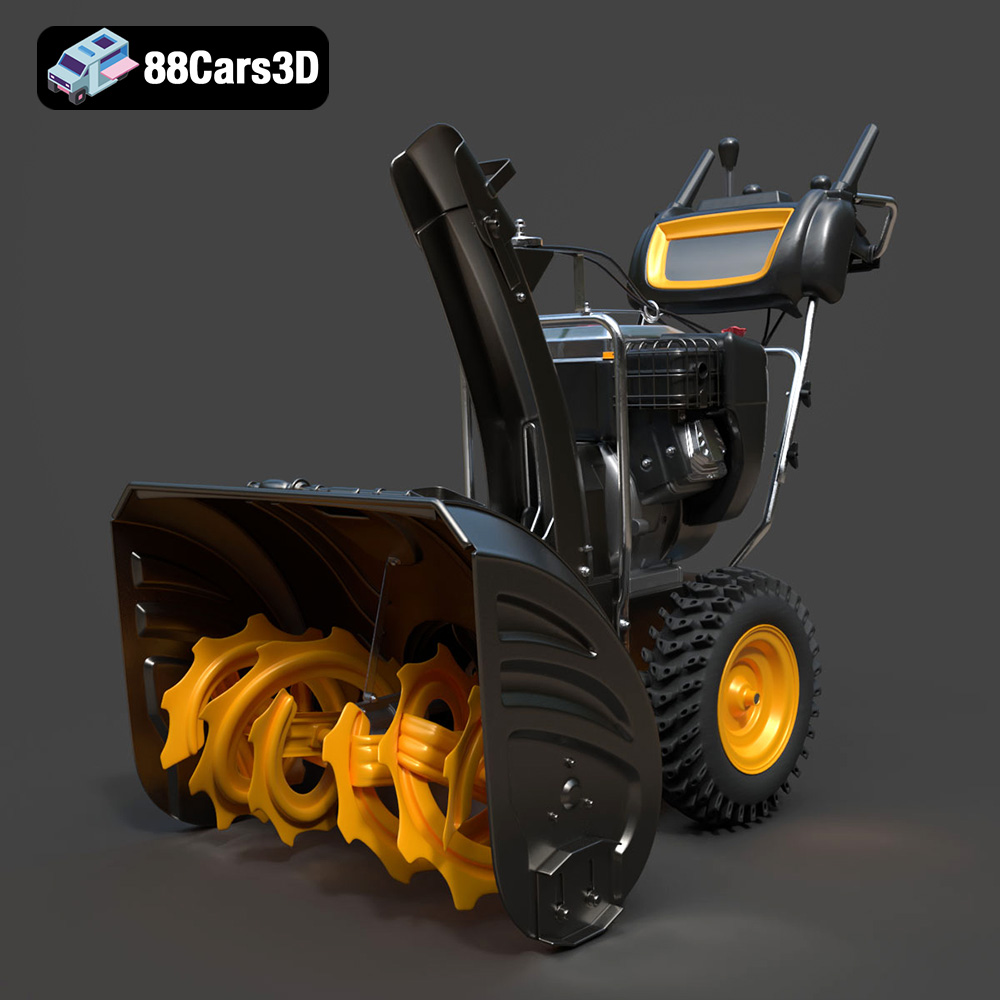
Texture: Yes | Material: Yes
Download the highly detailed, game-ready Husqvarna Snow Plow 3D Model. Features heavy-duty front plow blade, robust chassis, and realistic mechanical controls. Includes .blend, .fbx, .obj, .glb, .stl, .ply, .unreal, and .max formats for game development, AR/VR, and rendering.
Price: $145.50
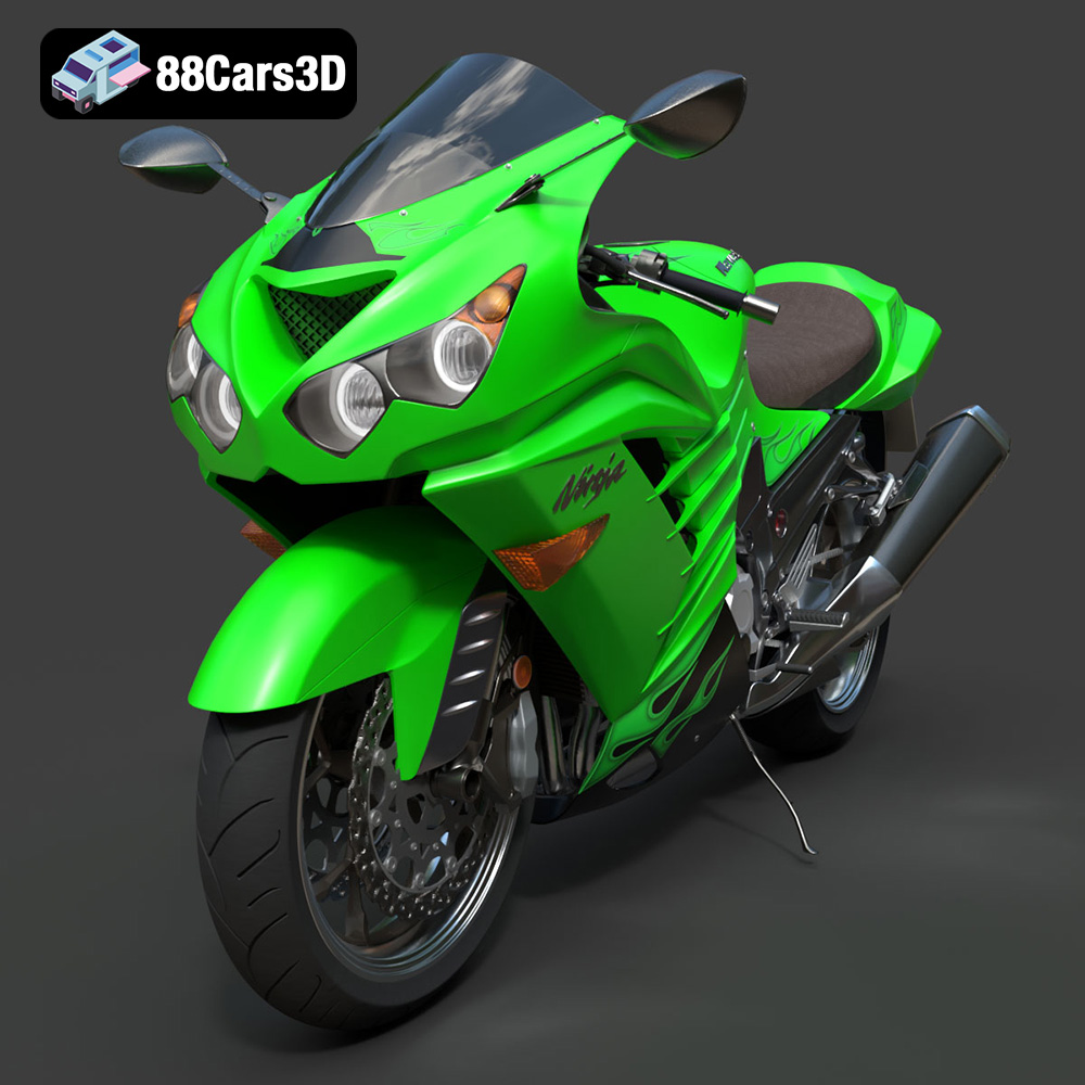
Texture: Yes | Material: Yes
Download the highly detailed, game-ready Kawasaki ZX14R 2012 3D Model. Features aggressive hyper-sport fairings, detailed inline-four engine, and iconic dual exhausts. Includes .blend, .fbx, .obj, .glb, .stl, .ply, .unreal, and .max formats for game development, AR/VR, and rendering.
Price: $170.00
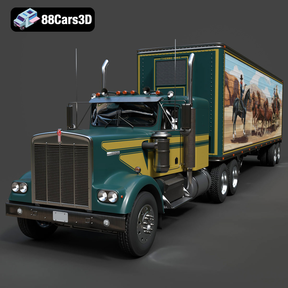
Texture: Yes | Material: Yes
Download the highly detailed, game-ready Kenworth W900 1974 3D Model. Features classic long-nose hood styling, detailed chrome exhaust stacks, and realistic dual tandem axles. Includes .blend, .fbx, .obj, .glb, .stl, .ply, .unreal, and .max formats for game development, AR/VR, and rendering.
Price: $299.50
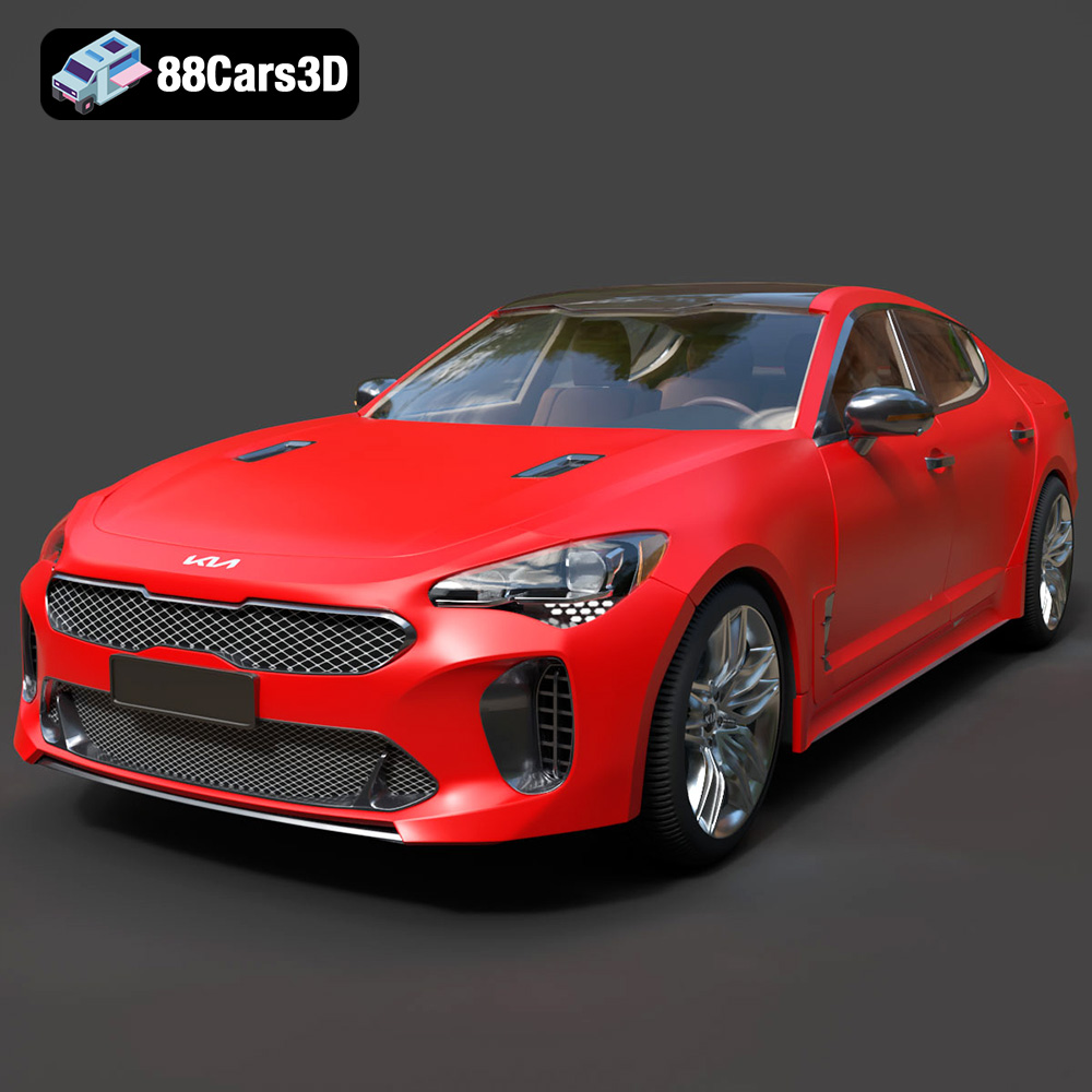
Texture: Yes | Material: Yes
Download the highly detailed, game-ready Kia Stinger 2021 3D Model. Features tiger-nose grille styling, quad exhaust tips, and high-fidelity interior details. Includes .blend, .fbx, .obj, .glb, .stl, .ply, .unreal, and .max formats for game development, AR/VR, and rendering.
Price: $299.50
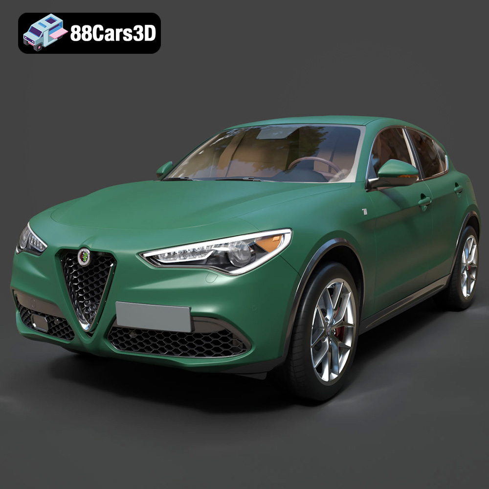
Texture: Yes | Material: Yes
Download the highly detailed, game-ready Alfa Romeo Stelvio Ti 2020 3D Model. Features signature Italian luxury SUV styling, detailed interior, and accurate chassis geometry. Includes .blend, .fbx, .obj, .glb, .stl, .ply, .unreal, and .max formats for game development, AR/VR, and rendering.
Price: $237.99
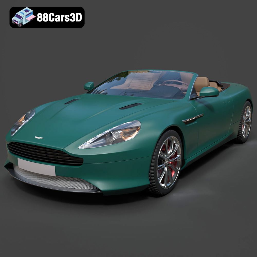
Texture: Yes | Material: Yes
Download the highly detailed, game-ready Aston Martin Virage Volante 2012 3D Model. Features sleek open-top GT design, iconic front grille, and detailed luxury interior trim. Includes .blend, .fbx, .obj, .glb, .stl, .ply, .unreal, and .max formats for game development, AR/VR, and rendering.
Price: $157.00

Texture: Yes | Material: Yes
Download the highly detailed, game-ready Audi Q4 e-tron 2021 3D Model. Features sleek electric SUV styling, signature Singleframe grille, and detailed Matrix LED lighting. Includes .blend, .fbx, .obj, .glb, .stl, .ply, .unreal, and .max formats for game development, AR/VR, and rendering.
Price: $299.50
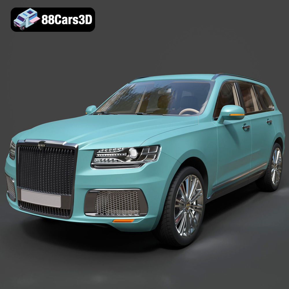
Texture: Yes | Material: Yes
Download the highly detailed, game-ready Aurus Komendant 2020 3D Model. Features an imposing front grille, executive full-size SUV silhouette, and detailed luxury interior. Includes .blend, .fbx, .obj, .glb, .stl, .ply, .unreal, and .max formats for game development, AR/VR, and rendering.
Price: $232.99
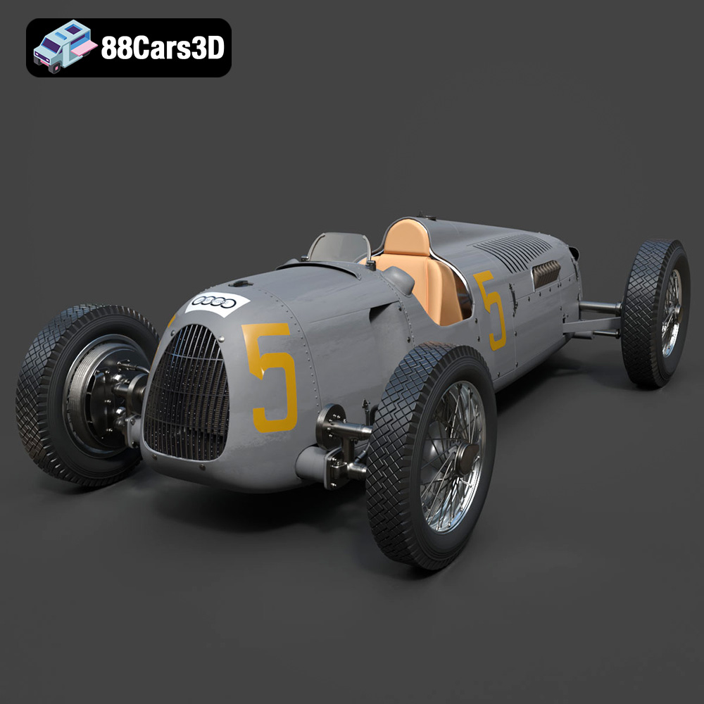
Texture: Yes | Material: Yes
Download the highly detailed, game-ready Auto Union Type C 1936 3D Model. Features iconic V16 engine detailing, classic Silver Arrows bodywork, and detailed open cockpit layout. Includes .blend, .fbx, .obj, .glb, .stl, .ply, .unreal, and .max formats for game development, AR/VR, and rendering.
Price: $152.00
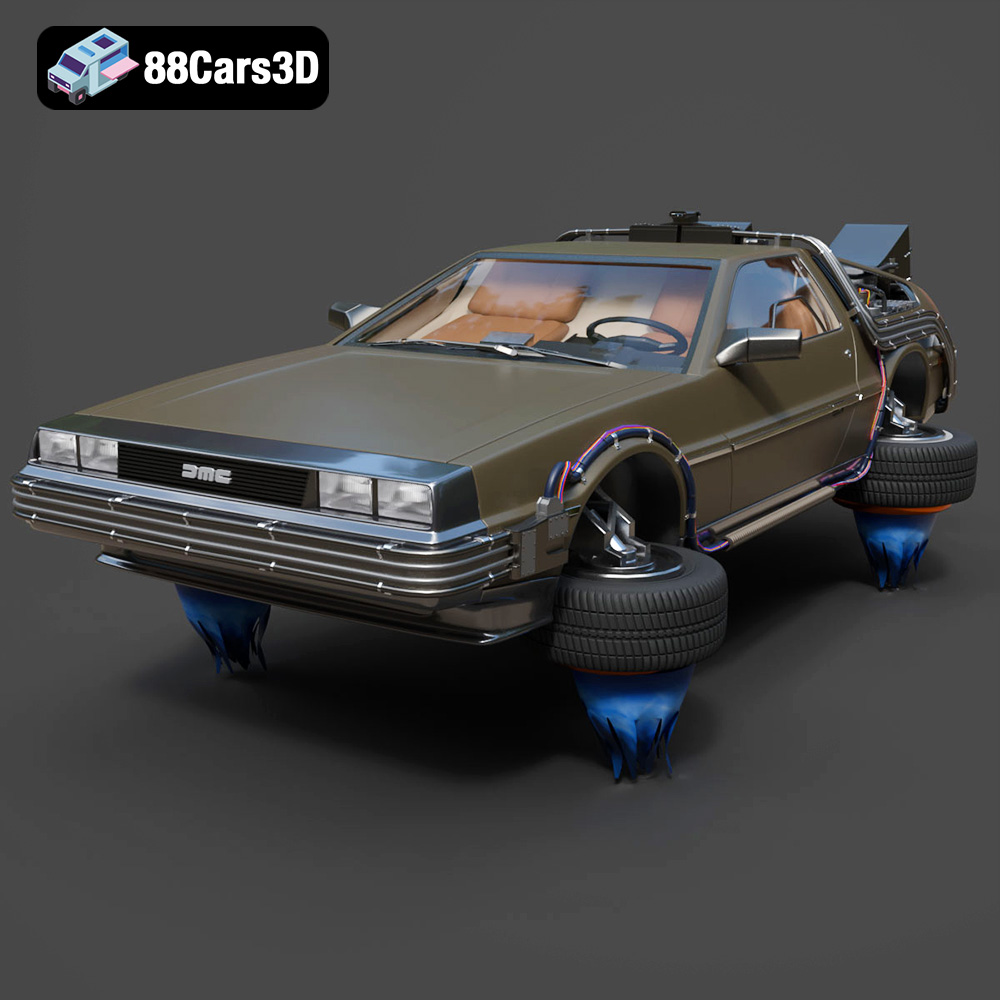
Texture: Yes | Material: Yes
Download the highly detailed, game-ready Back To The Future 2 DeLorean 3D Model. Features Mr. Fusion reactor, hover conversion wheels, and full flux capacitor interior. Includes .blend, .fbx, .obj, .glb, .stl, .ply, .unreal, and .max formats for game development, AR/VR, and rendering.
Price: $211.50
