
In the demanding world of 3D automotive design, visualization, and game asset development, precision is paramount. A beautifully rendered car model, whether destined for a cinematic animation, an immersive AR/VR experience, or a highly detailed 3D print, begins with a strong foundation of accuracy. This foundational element is often overlooked but is absolutely critical: high-quality reference blueprints. Without them, even the most skilled 3D artist can struggle to capture the intricate curves, exact proportions, and subtle nuances that define a real-world vehicle.
This comprehensive guide will delve deep into the art and science of utilizing reference blueprints within Blender, transforming your approach to 3D car models. We’ll explore everything from sourcing reliable blueprints and setting them up with surgical precision in your 3D viewport, to building clean, production-ready topology that respects the vehicle’s design intent. Whether you’re a seasoned professional looking to refine your workflow or an aspiring artist eager to tackle complex automotive shapes, mastering blueprint-driven modeling in Blender 4.4 is a skill that will elevate your work significantly. Platforms like 88cars3d.com thrive on models that showcase impeccable detail and realism, and this article will equip you with the knowledge to create exactly that.
Creating a convincing 3D car model from scratch without accurate references is akin to sculpting in the dark. Automotive design is an engineering marvel, a delicate balance of aerodynamics, aesthetics, and functionality, all meticulously planned to the millimeter. Blueprints serve as the definitive map, providing the exact dimensions, profiles, and angles from multiple orthographic views. This isn’t just about getting the general shape right; it’s about capturing the soul of the vehicle, which resides in its precise proportions and characteristic lines.
The demand for high-quality 3D car models is ever-growing, spanning industries from advertising and film to interactive media and rapid prototyping. For automotive rendering, an inaccurate model will immediately break the illusion of realism, regardless of how sophisticated the materials or lighting may be. In game development, even subtle discrepancies can lead to visual glitches or a lack of authenticity when compared to real vehicles. For AR/VR applications, where models are often viewed up close and from all angles, precise dimensions are non-negotiable for a believable experience. When preparing models for 3D printing, exact measurements are crucial to ensure physical fidelity. A slight error in a fender flare or a headlight housing can dramatically alter the perception of the car. Investing time in proper blueprint setup saves countless hours in later stages of the modeling process, preventing frustrating adjustments and rework. The expectation for high-fidelity models on marketplaces like 88cars3d.com underscores the necessity for this meticulous approach.
The quality of your final 3D model is directly tied to the quality of your reference images. Generic “side view” photos found online are often distorted by perspective or lens effects, making them unreliable for accurate modeling. The best blueprints are orthographic projections, meaning they show the object from a specific direction without any perspective distortion.
Here’s how to ensure you’re working with the best references:
* **Dedicated Blueprint Websites:** Websites specializing in car blueprints (e.g., The-Blueprints.com, BlueprintBox.com) are excellent resources. They often provide multiple high-resolution views (front, back, top, side, and sometimes diagonal or exploded views).
* **Manufacturer Data:** If possible, official manufacturer schematics or engineering drawings offer the highest level of accuracy. These are harder to come by but invaluable if accessible.
* **Consistency Check:** Always cross-reference multiple blueprints if available. Look for discrepancies in dimensions, wheel sizes, or key body lines. Sometimes, combining the best elements from several sources can yield a more accurate composite.
* **Resolution and Clarity:** Opt for high-resolution images. Blurry or pixelated blueprints make it difficult to discern fine details, leading to guesswork and inaccuracies in your model. Ensure the lines are clear and well-defined.
* **Scale Information:** Ideally, your blueprints will include scale indicators or known dimensions (e.g., overall length, wheelbase). This information is crucial for setting up your model to real-world scale in Blender.
Once you have your high-quality blueprints, the next critical step is to integrate them accurately into your Blender scene. This process requires methodical placement and scaling to ensure your 3D model aligns perfectly with every view. Blender 4.4 offers robust tools for handling reference images, which, when used correctly, create an ideal workspace.
The most efficient way to bring blueprints into Blender is using **Image Planes**. These are simple plane objects with your reference images applied as textures.
1. **Enable the “Import Images as Planes” Add-on:** If not already enabled, go to `Edit > Preferences > Add-ons`, search for “Images as Planes,” and activate it. This add-on is incredibly useful as it automatically creates correctly scaled and oriented planes.
2. **Import Your Blueprints:** In the 3D Viewport, press `Shift + A`, go to `Image > Images as Planes`. Navigate to your blueprint files.
3. **Choose Your Views:** Import each orthographic view (front, back, top, side) separately. When importing, you’ll want to adjust the “Offset” and “Emissive” settings. “Emissive” helps ensure the blueprint is always visible, regardless of scene lighting, and “Offset” positions the plane correctly. For example, for a side view, set the `Z` axis to 0 and rotate it along the `Y` axis by 90 degrees.
4. **Positioning:** Place each image plane in its respective orthographic view.
* **Side View:** Align the bottom of the wheels with the X-axis (ground plane) and the front of the car with the Z-axis (centerline).
* **Front View:** Align the bottom of the wheels with the X-axis and the center of the car with the Y-axis.
* **Top View:** Align the center of the car with the Y-axis.
* **Back View:** Similar to the front, but ensure it’s placed at the rear of the vehicle.
* Use the `G` (Grab), `R` (Rotate), and `S` (Scale) tools, combined with axis locking (X, Y, or Z), to precisely position each image. You can temporarily move objects to their own collection for easier management and visibility toggling.
Blender’s 3D Viewport allows you to set different background images per view (Front, Side, Top), but using image planes provides more flexibility, allowing you to manipulate their opacity, toggle visibility, and even move them around without affecting the view settings. For more detailed information on managing viewports and objects, consult the official Blender 4.4 documentation on the 3D Viewport: https://docs.blender.org/manual/en/4.4/editors/3dview/index.html.
Accurate scaling and alignment are crucial.
* **Establish Scale:** Find a known dimension on your blueprint (e.g., wheelbase, overall length, or height). Add a simple Blender primitive (e.g., a cube) and adjust its dimensions to match this real-world measurement. This will be your primary scale reference.
* **Aligning Views:**
1. Start with the side view. Scale the image plane until a key measurement (like the wheelbase) matches your reference cube.
2. Switch to the top view. Align the center line of the car with the global Y-axis. Scale this image plane to match the length established by the side view.
3. Repeat for the front and back views, aligning to the ground plane and centerlines, scaling them to match the width and height determined by the initial views.
4. Adjust the opacity of the image planes (`Object Data Properties > Transparency`) to make them less intrusive while modeling.
* **Tip:** Use Blender’s `Snapping` feature (Shift+Tab or magnet icon) to align vertices and edges precisely to your reference lines. In Edit Mode, you can snap to `Vertex`, `Edge`, or `Face`.
With perfectly aligned blueprints, you can now begin the exciting process of bringing your car to life in 3D. The quality of your topology and edge flow will dictate how well your model deforms, subdivides, and receives materials later on. It’s an art form in itself, especially for complex automotive surfaces.
Start with the largest, most dominant shapes. Resist the urge to dive into fine details.
* **Initial Primitives:** Begin by adding simple primitives like cubes for the main body block, cylinders for wheel arches, or planes for flat surfaces.
* **Conform to Blueprints:** In orthographic views (NumPad 1, 3, 7 for front, side, top), roughly scale and position these primitives to match the overall silhouette of the car as seen in your blueprints.
* **Mirror Modifier:** For symmetrical parts, always use a `Mirror Modifier`. This saves half your modeling time and ensures perfect symmetry. Apply it early in your workflow.
* **Iterative Refinement:** Gradually add more subdivisions (Ctrl+R for Loop Cut, or apply a Subdivision Surface modifier with a low viewport subdivision level) and move vertices to better conform to the blueprint curves. Think of it as slowly shrinking a wireframe cage around the car.
For 3D car models, especially those intended for rendering or animation, a clean, quad-dominant topology is non-negotiable. Quads (four-sided polygons) subdivide smoothly and allow for predictable deformation.
* **Edge Loops for Definition:** Ensure that edge loops follow the natural contours and creases of the car body. These loops will be crucial for holding sharp edges when using subdivision surfaces and for defining where panel lines or character lines exist.
* **Pole Management:** Aim to minimize N-gons (polygons with more than four sides) and triangles. While occasional triangles might be unavoidable in very complex areas, they should be used sparingly and strategically, typically on flat surfaces where deformation is minimal. Poles (vertices with more or less than four connecting edges) are also important to manage; typically, 3-edge poles and 5-edge poles are acceptable, but too many irregular poles can lead to shading artifacts.
* **Panel Line Flow:** Pay close attention to how the edge flow dictates the major car panels. The hood, doors, trunk, and fenders should ideally be defined by continuous edge loops, even if they are eventually separated into distinct objects. This ensures consistency and simplifies later detailing.
Car bodies are full of complex, flowing surfaces and intricate intersections.
* **Wheel Wells:** Start with a cylinder or a circle to define the primary shape of the wheel well and then integrate it into the main body mesh. Ensure the edge flow around the wheel arch is smooth and follows the curve of the blueprint.
* **Headlights and Grilles:** These areas often involve sharp cutouts and intricate details. Use the `Knife Project` tool (available in Edit Mode) to project shapes from a plane onto your car body, creating precise cutouts. Then, extrude these new faces to give them depth. For very complex grilles, it might be more efficient to model the individual elements and then use a Boolean modifier for the cutout, although this requires careful cleanup afterward. Remember, Boolean operations can often create messy topology, so a manual approach or diligent retopology might be necessary for a clean result. You can find more on Blender’s mesh editing tools and techniques in the official Blender 4.4 documentation: https://docs.blender.org/manual/en/4.4/modeling/meshes/editing/index.html.
Once the foundational mesh is robust, it’s time to refine the surface and introduce the smaller, yet critical, details that elevate a model from good to outstanding. Blueprints continue to serve as your guide for these finer elements.
Subdivision surface modeling is a cornerstone of creating smooth, organic shapes like car bodies.
* **Subdivision Surface Modifier:** Add a `Subdivision Surface Modifier` to your mesh. Start with a `Viewport` level of 1 or 2 to see the smoothed result in real-time. The `Render` level can be higher (e.g., 2 or 3) for final output. This modifier, documented in Blender’s manual, is crucial for turning your blocky base mesh into a sleek automotive form.
* **Holding Edges with Creases and Edge Loops:** While the Subdivision Surface modifier smooths, you’ll need to define sharp edges and creases where the blueprint indicates.
* **Edge Crease (Shift+E):** Select edges and apply a crease value. This is useful for quickly sharpening edges without adding geometry, but can sometimes lead to pinching if overused.
* **Control Edge Loops (Ctrl+R):** The preferred method for production-ready models is to add “control loops” parallel and close to the edges you want to sharpen. These loops effectively “tighten” the subdivision, creating a crisp line. For example, a sharp body line might have three edge loops defining it: one along the main line and two very close to it, one on each side. This ensures clean subdivision and better light reflection.
The devil is in the details, and for a car, panel gaps are a prime example.
* **Creating Realistic Panel Gaps:**
1. **Duplicate and Separate:** Select the faces that make up a panel (e.g., a door). Duplicate them (`Shift+D`) and then separate them into a new object (`P > Selection`).
2. **Solidify Modifier:** Apply a `Solidify Modifier` to the separated panel. This gives it thickness. Adjust the `Thickness` value to represent a realistic panel gap (often very small, around 0.5-1.5mm in real-world scale).
3. **Shrink/Fatten (Alt+S):** On the main body mesh, select the edge loops that define the panel gap. Use `Alt+S` (Shrink/Fatten) to slightly push these edges inward, creating a subtle recession. This, combined with the solidified panel, creates a convincing visual separation.
* **Beveling Panel Edges:** Apply a small bevel (`Ctrl+B`) to the edges of the panels and the edges of the main body where the gap exists. This catches light beautifully and enhances realism in rendering.
* **Integrating Interior Elements:** For detailed car models, blueprints often include basic interior layouts. Start by blocking out the dashboard, seats, and steering wheel with simple geometry, always referring back to your blueprints for proportion and placement. Even if the interior isn’t the primary focus, a well-blocked-out interior adds to the overall integrity and believability of the model.
Even with perfect geometry, a 3D car model won’t look realistic without high-quality UV mapping and well-crafted Physically Based Rendering (PBR) materials. These steps are crucial for applying textures that simulate real-world surface properties.
UV mapping is the process of flattening your 3D mesh into a 2D space so that textures can be applied. For complex automotive surfaces, this requires careful planning.
* **Strategic Seam Placement:** Mark seams (`Ctrl+E > Mark Seam`) along natural breaks in the car’s geometry, similar to how a car is assembled. Think of where panels meet, under the chassis, or along sharp creases that would be less visible. Avoid placing seams on highly visible, smooth surfaces if possible, as they can sometimes lead to texture stretching or visible seams in the final render.
* **Minimizing Distortion:** After marking seams, unwrap your mesh (`U > Unwrap` or `Smart UV Project`). The goal is to minimize distortion, ensuring that your textures appear even and consistent across the model. Use the `UV Editor` to inspect for stretched or compressed areas. You can select specific UV islands and use `Pack Islands` or `Average Island Scale` to optimize space.
* **Multi-UDIM Workflows:** For extremely high-resolution 3D car models, especially those for cinematic rendering, a single UV map might not suffice. UDIMs (U-Dimension) allow you to use multiple UV tiles (each acting as a separate texture space) to avoid pixel density limitations. For example, the body of the car could be on UDIM 1001, wheels on 1002, and interior elements on 1003. This enables incredibly detailed texture maps without sacrificing resolution. Blender 4.4’s UV Editor, as detailed in the official documentation (https://docs.blender.org/manual/en/4.4/editors/uv/index.html), is well-equipped to handle complex unwrapping tasks.
PBR materials accurately simulate how light interacts with surfaces in the real world, providing a much higher level of realism.
* **Car Paint:** This is often the most complex material. It typically involves:
* **Base Color:** The primary color of the paint.
* **Metallic:** High metallic value (close to 1) for a car paint shader.
* **Roughness:** Controls how glossy or matte the paint is. Often, a subtle texture or gradient can be used to simulate dust or slight imperfections.
* **Clearcoat:** Modern car paints have a clear protective layer. In Blender’s `Principled BSDF` shader, you can enable and adjust `Clearcoat` and `Clearcoat Roughness` for this effect.
* **Flakes (Optional):** For metallic paints, subtle glitter or flakes can be added using a `Noise Texture` or a dedicated flake shader, mixed in with the base color and metallic properties.
* **Glass:** Use a `Glass BSDF` shader with a high `IOR` (Index of Refraction, typically around 1.45-1.55 for glass) and minimal roughness for clear windows. For tinted glass, adjust the `Color` of the shader.
* **Chrome/Metals:** For shiny metals, a `Principled BSDF` with high `Metallic` (close to 1) and very low `Roughness` (close to 0) works well. Various textures can be plugged into the roughness and normal inputs to simulate brushed metal or subtle imperfections.
* **Tires:** A combination of `Principled BSDF` with low metallic, medium roughness, and a `Normal Map` derived from a tire tread texture is effective. Add some procedural `Noise` to the roughness for added realism.
* **Shader Networks:** In Blender’s `Shader Editor`, you’ll connect various texture nodes (Image Texture, Noise Texture, Voronoi Texture) and utility nodes (Math, Color Ramp, Mix RGB) to create complex and layered PBR materials. This node-based system offers immense flexibility for achieving photorealistic results.
Once your 3D car model is meticulously modeled and textured, the final frontier for achieving breathtaking realism lies in thoughtful lighting and environment setup. This stage transcends mere technical application and enters the realm of artistic vision, where light sculpts form and reveals material properties.
High Dynamic Range Images (HDRIs) are an industry standard for realistic lighting and reflections, especially for automotive rendering.
* **Why HDRIs?** HDRIs capture real-world lighting information, including intensity and color, from a full 360-degree environment. When used in Blender, they provide not only realistic lighting but also accurate reflections on the glossy surfaces of your car, which are crucial for showcasing the intricate bodywork.
* **Implementation in Blender:**
1. Switch to the `Shader Editor` and select `World` from the dropdown menu.
2. Delete the default `Background` node.
3. Add an `Environment Texture` node (`Shift+A > Texture > Environment Texture`).
4. Click `Open` and load your HDRI file (typically a `.hdr` or `.exr` format).
5. Connect the `Color` output of the `Environment Texture` to the `Color` input of a `Background` node, and the `Background` node’s `Background` output to the `World Output` node.
6. For more control over rotation, add a `Mapping` node and `Texture Coordinate` node (`Shift+A > Input > Texture Coordinate`, `Shift+A > Vector > Mapping`) between the `Environment Texture` and `Background` nodes, connecting `Generated` to `Vector` on the Mapping node, and `Vector` from Mapping to `Vector` on the Environment Texture. Rotate the `Z` axis on the Mapping node to change the direction of your lighting.
* **Complementary Lighting:** While HDRIs provide excellent ambient lighting, supplementary lights are often necessary to emphasize specific details, create dramatic shadows, or add rim lighting.
* **Area Lights:** Use large `Area Lights` with soft shadows to simulate studio lighting or a bright sky. Position them to highlight the car’s curves.
* **Spot Lights:** Smaller `Spot Lights` can be used to add sharp highlights to chrome, badges, or specific body lines, drawing the viewer’s eye.
* **Mesh Lights:** For accurate headlight or taillight illumination, model the light housing and use an `Emission` shader on the internal geometry, effectively turning the mesh into a light source.
A compelling render goes beyond just the car; the environment tells a story.
* **Simple Ground Plane:** Start with a basic `Plane` scaled up considerably to act as the ground. This helps with shadows and reflections.
* **Backdrop or Cyclorama:** For studio-style renders, create a seamless backdrop using a curved plane (often called a cyclorama or “cyc”). Extrude an edge of your ground plane upwards and then bevel the corner for a smooth transition.
* **Detailed Scenes:** For more elaborate renders, consider adding basic architectural elements, roads, or natural landscapes. These can be simplified models or purchased assets. Ensure the scale and perspective of your environment elements match your car and blueprint.
* **Reflective Surfaces:** Incorporate additional reflective surfaces in the environment, even subtle ones. A slightly glossy floor or background element will enhance the realism of your car’s reflections, making it appear more integrated into the scene.
Creating a beautiful 3D car model is only half the battle; preparing it for real-time environments like game engines (Unity, Unreal Engine) or interactive AR/VR applications requires a different set of considerations focused on performance. Efficient asset management and correct file format conversions are key here.
Game engines and AR/VR platforms demand highly optimized models to maintain smooth frame rates.
* **Polygon Count Management:** While high-poly models look great in offline renders, they can cripple real-time performance.
* **Decimate Modifier:** Use Blender’s `Decimate Modifier` (in `Collapse` mode) to reduce polygon count while preserving the overall shape. Apply it carefully and iteratively.
* **Manual Retopology:** For critical areas, manual retopology to create a lower-polygon mesh from a high-polygon sculpt is often necessary. This ensures optimal edge flow for animation and deformation. A typical high-quality game asset might aim for 50,000-150,000 polygons for a full car, with extreme optimization for mobile VR platforms dropping to 20,000-50,000.
* **Level of Detail (LODs):** Implement multiple versions of your car model, each with a decreasing polygon count.
* **LOD Group Setup:** In game engines, `LOD Groups` automatically swap between these versions based on the camera’s distance, ensuring performance without sacrificing visual quality up close.
* **Baking Normal Maps:** High-resolution details from your high-poly model can be baked onto the low-poly version as `Normal Maps`. This creates the illusion of detail without adding geometry. This process is essential for achieving visual fidelity with optimized models.
* **Texture Atlasing:** Combine multiple smaller textures into a single, larger texture map (an atlas). This reduces the number of `draw calls` (instructions sent to the GPU), improving performance. For a car, this might mean combining textures for the dashboard, seats, and steering wheel into one atlas.
* **Occlusion Culling:** Utilize occlusion culling in game engines to prevent rendering objects that are hidden behind other objects. This is particularly useful for car interiors when the camera is outside the vehicle.
Exporting your model correctly is crucial for seamless integration into other software.
* **FBX (Filmbox):** This is the industry-standard exchange format for 3D data, widely supported by game engines like Unity and Unreal Engine. When exporting from Blender, ensure you select appropriate options for `Scale` (usually FBX Unit Scale) and `Smoothing` (Face or Edge). You’ll typically want to export with `Selected Objects`, `Mesh`, `Armature` (if rigged), and `Animation` (if present).
* **OBJ (Wavefront Object):** A simpler, widely supported format primarily for mesh data. Good for static models, but doesn’t carry animation, rigging, or complex material definitions well. Often used for 3D printing.
* **GLB/glTF (Graphics Library Transmission Format):** An increasingly popular open standard, especially for web-based 3D, AR, and VR. It supports PBR materials, animations, and scene hierarchy. It’s an excellent choice for efficient web deployment of 3D car models. Blender’s glTF 2.0 exporter is robust.
* **USDZ (Universal Scene Description Zip):** Apple’s format for AR applications. Similar to glTF but optimized for Apple’s ecosystem. Converting glTF to USDZ is a common workflow.
* **Checking Compatibility:** Always test your exported models in the target software. Look for issues with scale, material assignment, mesh integrity, and pivot points.
The rendering process generates raw image data. Post-processing and compositing are where that raw data is transformed into a polished, professional image or animation. This stage can dramatically enhance the mood, realism, and visual impact of your 3D car models.
Blender’s built-in `Compositor` is a powerful node-based environment for post-processing your renders.
* **Activating Compositing:** In Blender, switch to the `Compositing` workspace. Enable `Use Nodes` and `Backdrop`. Connect the `Render Layers` node to a `Viewer` node to see your render in the background.
* **Color Grading and Correction:**
* **Color Balance Node:** Adjust the lift (blacks), gamma (midtones), and gain (whites) for color correction. You can also shift colors in the shadows, midtones, and highlights to set a mood.
* **RGB Curves Node:** Provides granular control over the luminance and individual color channels (Red, Green, Blue) of your image, allowing for precise color grading.
* **Brightness/Contrast Node:** Basic adjustments for overall image brightness and contrast.
* **Atmospheric Effects:**
* **Glare Node:** Add bloom or glare effects to bright areas, simulating light scattering in the camera lens. This is particularly effective for headlights, taillights, and reflections on chrome.
* **Fog/Mist Pass:** If you render a mist pass (available in `View Layer Properties > Passes > Z`), you can use a `Map Range` node and `Mix` node to add volumetric fog, enhancing depth.
* **Depth of Field:** If not rendered in the 3D viewport, you can simulate depth of field using the `Defocus` node with a Z-pass (Depth pass). This allows you to blur foreground and background elements, drawing focus to your car.
* **Vignette:** A subtle darkening of the image edges can help frame your subject. This can be achieved with a `Lens Distortion` node or by layering a dark gradient.
* **Render Passes (AOV – Arbitrary Output Variables):** For maximum flexibility, render your car with multiple passes. Beyond the standard RGBA, useful passes include:
* **Diffuse Color/Direct/Indirect:** Separate components of diffuse light.
* **Glossy Direct/Indirect:** Separate components of specular reflections.
* **Transmission:** For transparent objects like glass.
* **Normal Pass:** Useful for re-lighting or adding fake reflections in compositing.
* **Z-Pass (Depth Pass):** Essential for depth of field and fog.
* **Ambient Occlusion (AO):** Provides contact shadows, enhancing realism.
These passes allow you to adjust each aspect of the lighting and material response independently in compositing, giving you unparalleled control without re-rendering the entire scene.
* **External Compositing Software:** For complex projects, professionals often use dedicated compositing software like Adobe After Effects, Nuke, or DaVinci Resolve. Exporting your render passes as multi-layer EXR files from Blender allows these programs to leverage the full depth and channel information.
* **Match Plate Photography:** If you are integrating your 3D car into a photographic background (backplate), ensure that your 3D camera’s focal length, perspective, and lighting match the real photograph precisely. Using a `Camera Tracking` workflow in Blender can help achieve this. This is common for automotive advertising and visualization.
The journey from a simple concept to a fully realized, photorealistic 3D car model is an intricate process, demanding both technical skill and an artist’s eye. At its core, the meticulous use of reference blueprints in Blender 4.4 forms the bedrock of accuracy and authenticity. By understanding how to properly set up these vital guides, construct clean and efficient topology, apply advanced modeling techniques, and craft PBR materials with precision, you empower yourself to create automotive masterpieces.
The techniques discussed, from precise blueprint alignment and subdivision surface sculpting to intelligent UV mapping and game-ready optimization, are not just theoretical concepts. They are actionable strategies that professional 3D artists employ daily to produce stunning results for rendering, game development, AR/VR experiences, and even accurate 3D printing. The attention to detail in topology and PBR material setup ensures that your creations will not only look visually appealing but will also perform optimally across various platforms and applications.
Remember, the goal is not merely to replicate a vehicle, but to imbue your 3D car models with the inherent design integrity of the original. By embracing these best practices, you are not just building models; you are crafting digital assets that command respect and captivate audiences. Whether you’re aiming for breathtaking renders or optimized game assets, the foundations laid with accurate blueprints will serve you well. For those looking to acquire or showcase truly exceptional 3D car models, platforms like 88cars3d.com serve as a testament to the high standards achievable through this dedicated approach. Continue to hone your craft, experiment with advanced techniques, and always strive for that pixel-perfect fidelity that sets truly great 3D automotive artists apart.
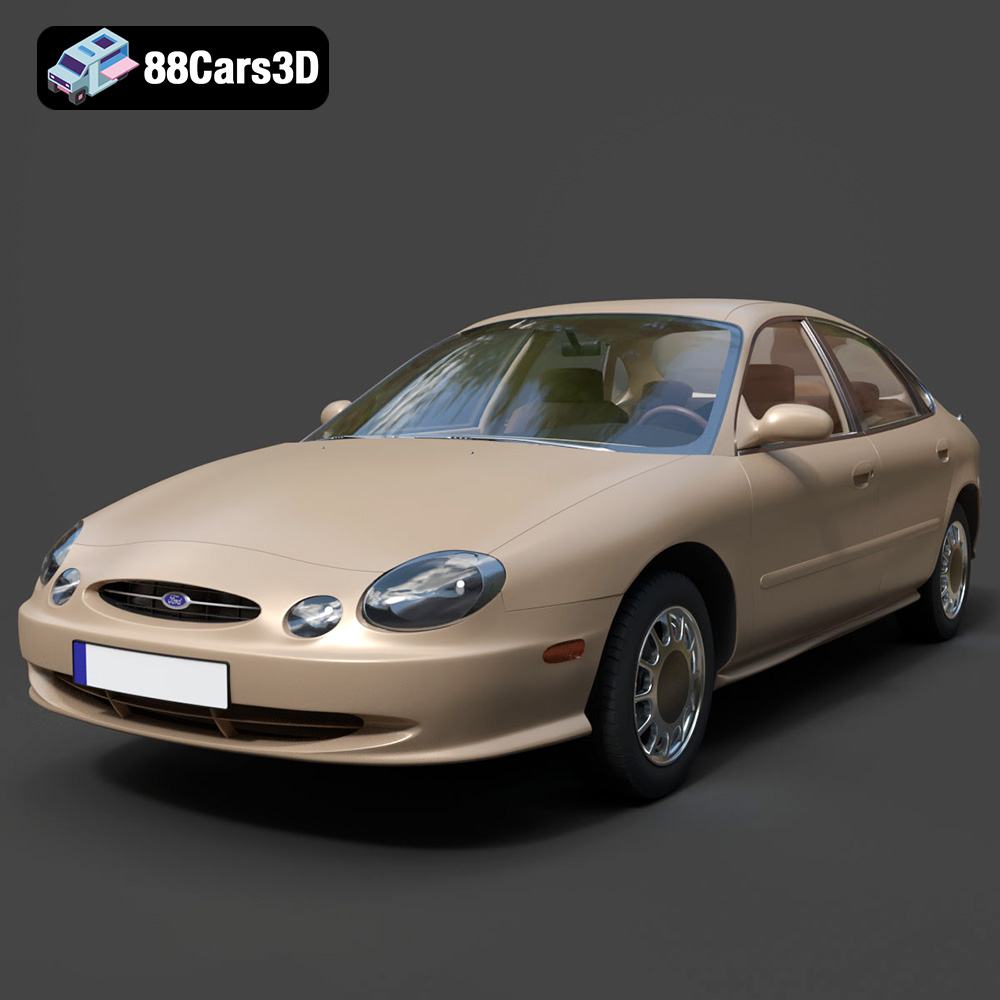
Texture: Yes | Material: Yes
Download the highly detailed, game-ready Ford Taurus 1996 3D Model. Features revolutionary oval exterior styling, detailed interior, and accurate chassis geometry. Includes .blend, .fbx, .obj, .glb, .stl, .ply, .unreal, and .max formats for game development, AR/VR, and rendering.
Price: $161.00
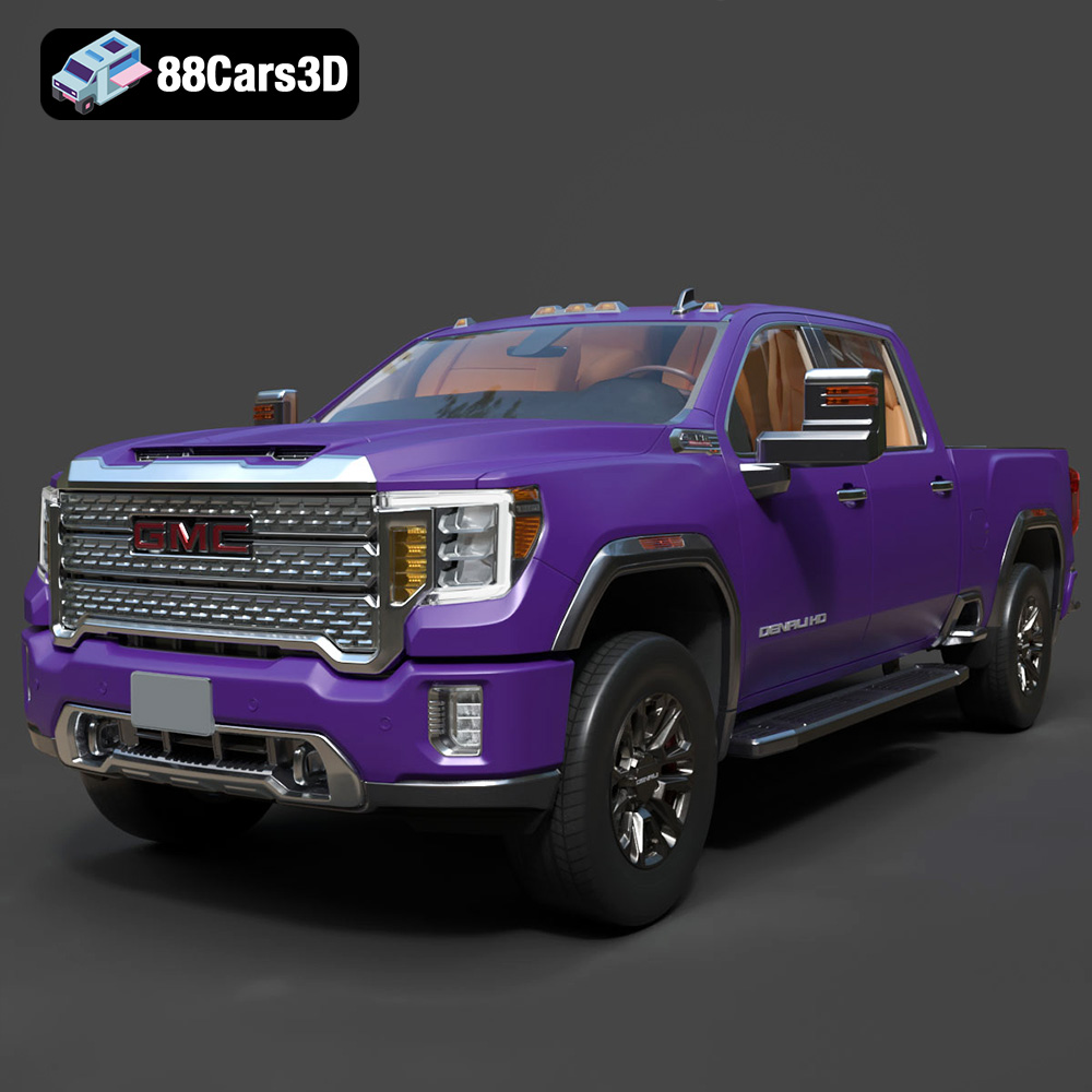
Texture: Yes | Material: Yes
Download the highly detailed, game-ready GMC Sierra HD Denali 2020 3D Model. Features iconic chrome Denali grille, detailed MultiPro tailgate, and heavy-duty chassis styling. Includes .blend, .fbx, .obj, .glb, .stl, .ply, .unreal, and .max formats for game development, AR/VR, and rendering.
Price: $274.50
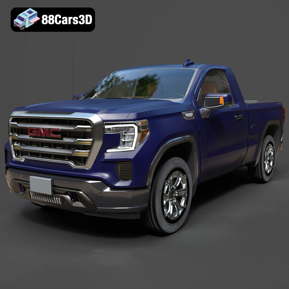
Texture: Yes | Material: Yes
Download the highly detailed, game-ready GMC Sierra Reg SLE 1500 2020 3D Model. Features bold pickup styling, detailed exterior trim, accurate undercarriage, and realistic cabin. Includes .blend, .fbx, .obj, .glb, .stl, .ply, .unreal, and .max formats for game development, AR/VR, and rendering.
Price: $133.50
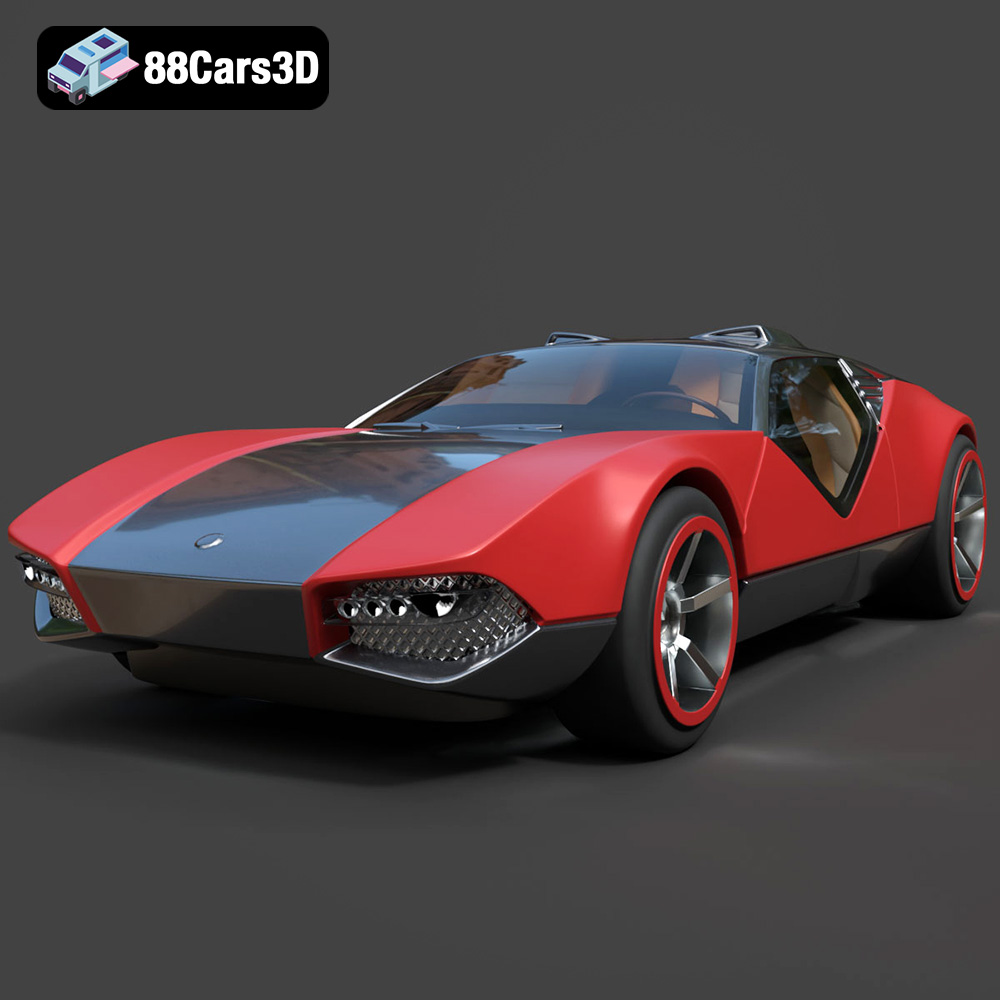
Texture: Yes | Material: Yes
Download the highly detailed, game-ready Hot Wheels La Fasta 3D Model. Features aggressive aerodynamic bodywork, custom racing wheels, and futuristic interior details. Includes .blend, .fbx, .obj, .glb, .stl, .ply, .unreal, and .max formats for game development, AR/VR, and rendering.
Price: $133.00
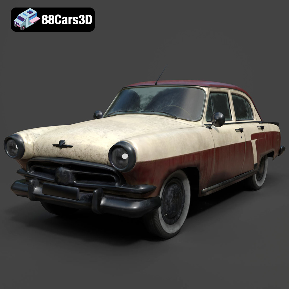
Texture: Yes | Material: Yes
Download the highly detailed, game-ready GAZ-21 Volga 3D Model. Features classic Soviet body geometry, iconic front grille, and detailed exterior chrome accents. Includes .blend, .fbx, .obj, .glb, .stl, .ply, .unreal, and .max formats for game development, AR/VR, and rendering.
Price: $99.99
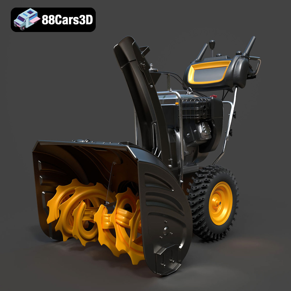
Texture: Yes | Material: Yes
Download the highly detailed, game-ready Husqvarna Snow Plow 3D Model. Features heavy-duty front plow blade, robust chassis, and realistic mechanical controls. Includes .blend, .fbx, .obj, .glb, .stl, .ply, .unreal, and .max formats for game development, AR/VR, and rendering.
Price: $145.50
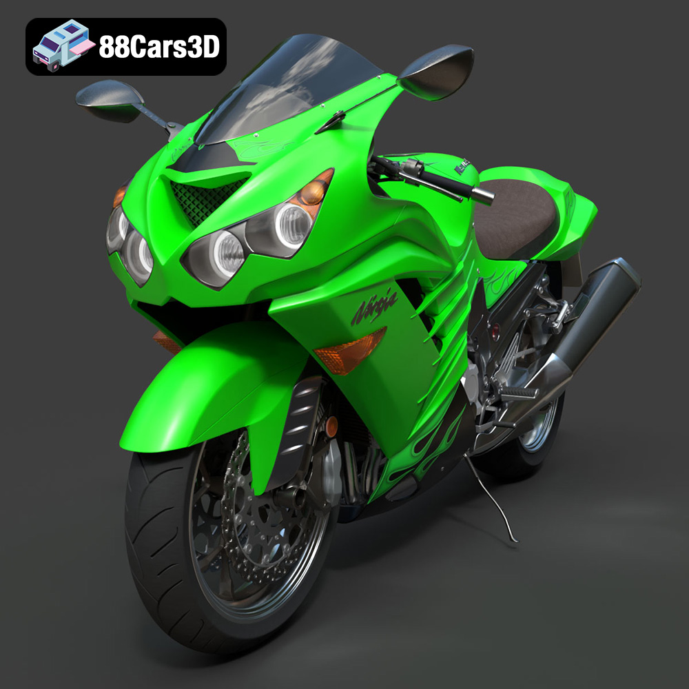
Texture: Yes | Material: Yes
Download the highly detailed, game-ready Kawasaki ZX14R 2012 3D Model. Features aggressive hyper-sport fairings, detailed inline-four engine, and iconic dual exhausts. Includes .blend, .fbx, .obj, .glb, .stl, .ply, .unreal, and .max formats for game development, AR/VR, and rendering.
Price: $170.00
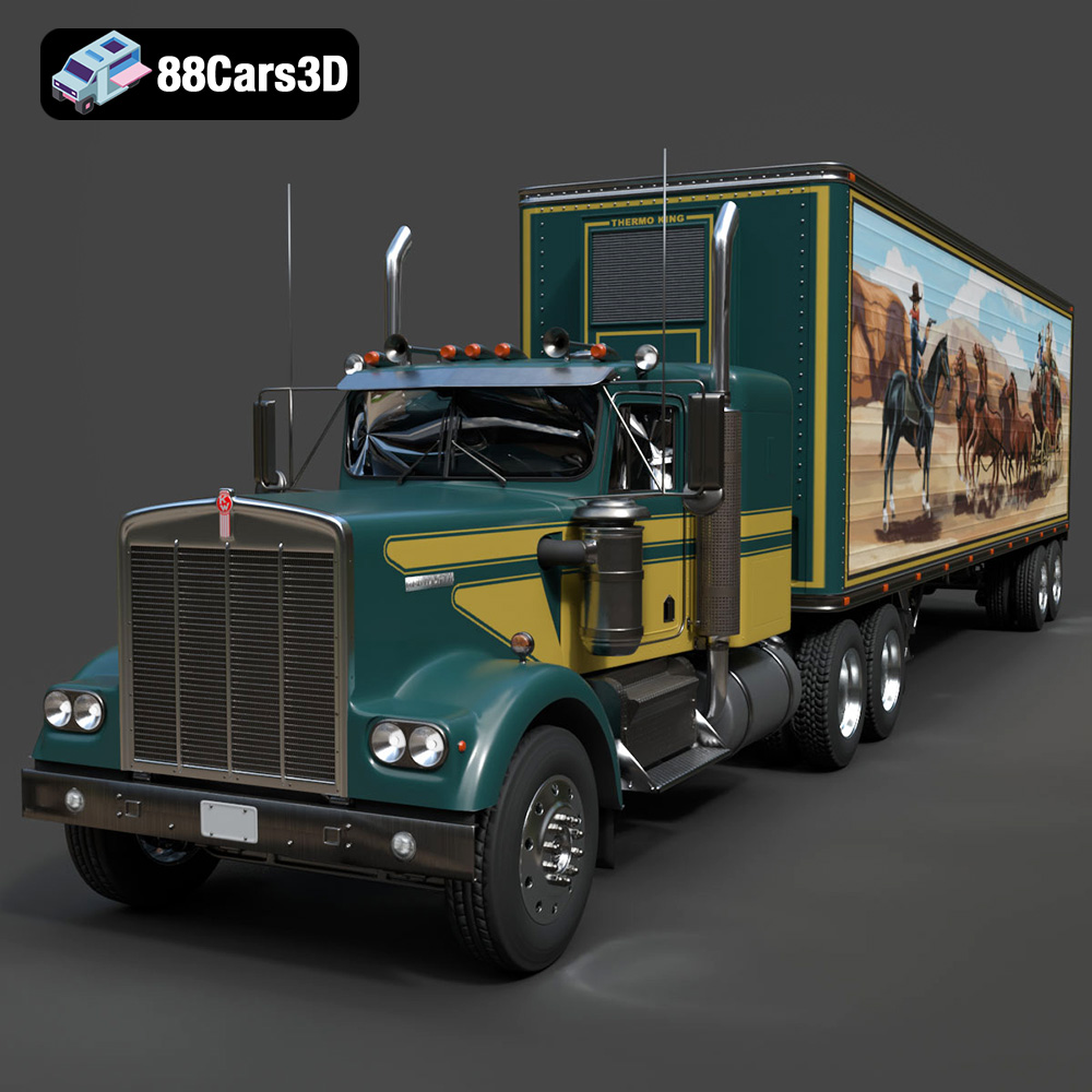
Texture: Yes | Material: Yes
Download the highly detailed, game-ready Kenworth W900 1974 3D Model. Features classic long-nose hood styling, detailed chrome exhaust stacks, and realistic dual tandem axles. Includes .blend, .fbx, .obj, .glb, .stl, .ply, .unreal, and .max formats for game development, AR/VR, and rendering.
Price: $299.50
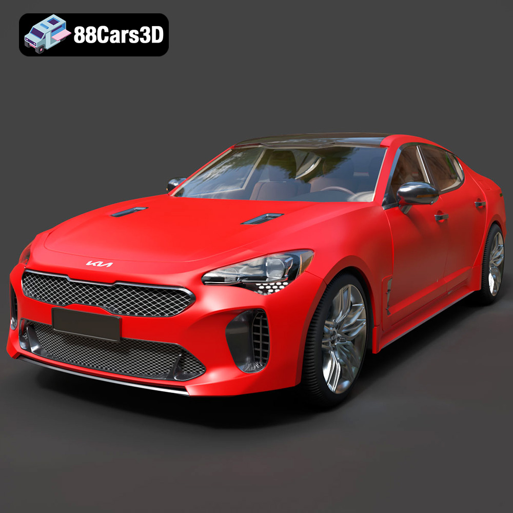
Texture: Yes | Material: Yes
Download the highly detailed, game-ready Kia Stinger 2021 3D Model. Features tiger-nose grille styling, quad exhaust tips, and high-fidelity interior details. Includes .blend, .fbx, .obj, .glb, .stl, .ply, .unreal, and .max formats for game development, AR/VR, and rendering.
Price: $299.50
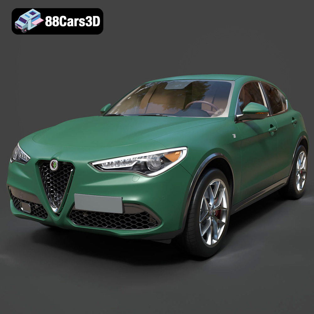
Texture: Yes | Material: Yes
Download the highly detailed, game-ready Alfa Romeo Stelvio Ti 2020 3D Model. Features signature Italian luxury SUV styling, detailed interior, and accurate chassis geometry. Includes .blend, .fbx, .obj, .glb, .stl, .ply, .unreal, and .max formats for game development, AR/VR, and rendering.
Price: $237.99
