
Automotive visualization in real-time engines has reached a threshold where standard material setups are no longer sufficient to meet the exacting standards of commercial rendering, cinematic production, and interactive configurators. While Unreal Engine’s visual Material Editor provides an incredible array of built-in nodes for Physically Based Rendering (PBR), pushing the boundaries of realism requires direct access to High-Level Shader Language (HLSL). Custom HLSL shaders grant developers surgical control over light-surface interactions, micro-facet distribution functions, anisotropic reflections, multi-layered clear coats, and high-performance procedural effects.
In this technical deep dive, we will explore advanced HLSL shader development specifically tailored for automotive visualization and high-performance real-time graphics in Unreal Engine. We will cover the mechanics of Unreal’s shader compilation pipeline, custom HLSL node development, shading model modifications, procedural metallic flake algorithms, and optimization strategies necessary to maintain 60+ FPS framerates under heavy rendering loads. Whether you are building interactive showroom applications or virtual production setups, mastering custom HLSL will elevate your real-time visual fidelity to photographic levels.
—
Unreal Engine’s Material Editor is essentially a visual wrapper around a powerful HLSL code generation framework. Every node placed in the graph translates into snippet blocks within an engine-generated shader file during the compilation phase. However, when working on hyper-realistic automotive assets—such as those sourced from professional asset libraries like 88cars3d.com—standard material graphs can become excessively node-heavy, leading to maintainability issues and suboptimal instruction execution on the GPU.
When Unreal Engine compiles a material, it parses the node graph and translates it into HLSL code, injecting it into core template files such as MaterialTemplate.ush. These files, written in Unreal Shader Format (USF) and Unreal Shader Header (USH) syntax, reside deep within the engine’s system files. The engine constructs a comprehensive Pixel Shader (and Vertex Shader) function that computes the final properties of the material, including Base Color, Metallic, Roughness, Specular, and World Normal.
To inspect or extend this pipeline, developers can leverage Unreal’s internal developer flags. By enabling shader development mode, you can inspect generated HLSL code directly. Add the following line to your project’s Config/DefaultEngine.ini file:
[DevOptions.Shaders]
r.ShaderDevelopmentMode=1
When activated, this mode allows live recompilation of shaders using the key combination Ctrl + Shift + Period, vastly speeding up custom HLSL iteration times without requiring a full engine restart. For comprehensive documentation on shader architecture and runtime configuration, consult the Unreal Engine Learning Ecosystem.
There are two primary avenues for writing custom HLSL code in Unreal Engine:
ShadingModels.ush, DeferredLightingCommon.ush). This approach modifies how light interacts with geometry at the deferred rendering level, enabling entire custom lighting pipelines such as specialized multi-coat paint models or thin-film interference shaders.Writing inline code inside the small text field of a Material Custom Node can quickly become cumbersome. Professional shader engineers write HLSL code in external IDEs such as Visual Studio Code, Visual Studio 2022, or Rider, and reference external .ush files via custom include directives inside the node. To enable external file inclusions, create a custom shader directory mapping in C++ or use relative path referencing within your project structure.
// Example Custom Node snippet referencing an external USH file
#include "/Project/Shaders/CarPaintFlakes.ush"
return ComputeMetallicFlakes(UV, FlakeDensity, FlakeScale, CameraVector, Normal);
—
Automotive surfaces represent some of the most challenging materials to simulate realistically in real-time rendering. Modern car paint consists of multiple physical layers: a primer coat, a base color coat containing microscopic metallic flakes or mica particles, and a glossy, protective clear coat layer. Standard single-layer PBR models fail to capture the subtle color shifts, depth, and micro-sparkle characteristics of automotive finishes.
Simulating metallic car paint requires generating millions of microscopic, randomly oriented reflective surfaces beneath the top coat. Using high-resolution texture maps for flakes often leads to severe Moiré patterns, texture tiling artifacts, and excessive VRAM usage. A procedural HLSL approach generates dynamic, infinity-scalable metallic flakes directly on the GPU.
Below is an optimized custom HLSL function designed for calculating procedural metallic flakes based on 3D micro-surface normals and camera angles:
// Custom HLSL: Procedural Metallic Flake Normal & Reflection Generator
// Inputs: float2 UV, float FlakeScale, float FlakeDensity, float3 WorldNormal, float3 WorldPos

float3 CellID;
float3 CellOffset;
float2 ScaledUV = UV * FlakeScale;

// Procedural 3D Voronoi/Grid Hash for spatial jittering
float3 FlakeNormal = WorldNormal;
float Intensity = 0.0;

for (int x = -1; x <= 1; x++)
{
    for (int y = -1; y <= 1; y++)
    {
        float2 Lattice = float2(x, y);
        float2 CellOrigin = floor(ScaledUV) + Lattice;

        // Pseudo-random hash for flake orientation
        float3 Hash = frac(sin(float3(dot(CellOrigin, float2(127.1, 311.7)),
                                      dot(CellOrigin, float2(269.5, 183.3)),
                                      dot(CellOrigin, float2(419.2, 371.9)))) * 43758.5453);

        if (Hash.x < FlakeDensity)
        {
            float2 FlakePos = CellOrigin + Hash.yz;
            float Dist = length(ScaledUV - FlakePos);

            if (Dist < 0.5)
            {
                // Randomize flake micro-normal vectors
                float3 MicroNormal = normalize(float3((Hash.xy - 0.5) * 2.0, Hash.z));
                FlakeNormal = normalize(WorldNormal + MicroNormal * 0.35);
                Intensity = pow(1.0 - Dist * 2.0, 2.0) * Hash.x;
            }
        }
    }
}

return float4(FlakeNormal, Intensity);
This code generates spatial cells across the material’s surface, assigning pseudo-random normal orientations to each cell. When lit by dynamic directional lights or HDRI environments, individual flakes glint dynamically as the camera moves past the vehicle bodywork.
The top layer of modern car paint acts as a smooth dielectric medium, reflecting high-frequency environment details while transmitting light down into the pigment layer. While Unreal Engine includes a native Clear Coat shading model, custom HLSL nodes allow developers to fine-tune Fresnel falloffs, refractive indices (IOR), and absorption effects along light transmission paths.
The standard Fresnel reflection coefficient is approximated using Schlick’s formula:
F(θ) = F0 + (1 – F0) * (1 – cos(θ))^5
In custom HLSL, we can extend this to account for light attenuation through tinted clear coats (such as candy coat finishes):
// Custom HLSL: Tinted Clear Coat Attenuation
// Inputs: float3 BaseColor, float3 ClearCoatTint, float VoH, float ClearCoatThickness, float IOR

// Fresnel reflectance calculation for dielectric boundary
float F0 = pow((1.0 - IOR) / (1.0 + IOR), 2.0);
float Fresnel = F0 + (1.0 - F0) * pow(1.0 - saturate(VoH), 5.0);

// Optical path length approximation based on viewing angle
float PathLength = ClearCoatThickness / (saturate(VoH) + 0.001);

// Beer-Lambert law for absorption through clear coat medium
float3 Transmittance = exp(-ClearCoatTint * PathLength);

float3 FinalColor = lerp(BaseColor * Transmittance, float3(1.0, 1.0, 1.0), Fresnel);
return FinalColor;
High-performance sports cars and supercars frequently incorporate structural or accent carbon fiber elements. Carbon fiber features weave patterns where light reflects differently depending on the direction of the woven strands—a property known as anisotropy.
Using custom HLSL within an Unreal Material, we calculate specular highlights based on the surface tangent ($T$) and bitangent ($B$) vectors rather than relying solely on surface normals ($N$):
// Custom HLSL: Anisotropic Highlight for Carbon Fiber Weaves
// Inputs: float3 Tangent, float3 Bitangent, float3 LightDir, float3 ViewDir, float RoughnessT, float RoughnessB

float3 H = normalize(LightDir + ViewDir);
float NdotL = saturate(dot(WorldNormal, LightDir));
float NdotV = saturate(dot(WorldNormal, ViewDir));

float TdotH = dot(Tangent, H);
float BdotH = dot(Bitangent, H);
float NdotH = dot(WorldNormal, H);

// Anisotropic GGX Microfacet Distribution
float D = TdotH * TdotH / (RoughnessT * RoughnessT) + BdotH * BdotH / (RoughnessB * RoughnessB) + NdotH * NdotH;
D = 1.0 / (3.14159 * RoughnessT * RoughnessB * D * D);

return D * NdotL;
—
While Custom Material Nodes are powerful, they execute within the boundaries of Unreal’s standard PBR material pipeline. For studios looking to implement bespoke lighting equations across thousands of assets without adding node complexity to every material graph, creating custom USF files or altering engine-level shading models is the ultimate technical solution.
Unreal Engine’s deferred renderer executes pixel shading routines within DeferredLightingCommon.ush and ShadingModels.ush. By adding a new entry to the EShadingModel enum in C++ source code (EngineTypes.h) and updating the corresponding USF shader files, you can integrate a custom automotive shading pipeline directly into the engine’s core.
In ShadingModels.ush, lighting calculations are partitioned based on the active shading model. A simplified structural addition for a bespoke “Automotive Multi-Coat” shading model looks as follows:
// Modified snippet from ShadingModels.ush
FDirectLighting AutomotiveMultiCoatBxDF( FGBufferData GBuffer, float3 GBufferNormal, float3 RayDirection, float3 RoutingData, FLightingContext Context )
{
    FDirectLighting Lighting;

    // Standard GGX Specular Base
    float3 SpecularGGX = StandardShadingSpec(GBuffer, Context.NdotL, Context.NdotV, Context.NdotH);

    // Custom Flake Layer Lighting Contribution
    float3 FlakeSpecular = ComputeCustomFlakeBRDF(GBuffer.CustomData.xyz, Context.H, Context.NdotL);

    // Combine base, flakes, and top-coat dielectric reflections
    Lighting.Diffuse = GBuffer.DiffuseColor * Context.NdotL;
    Lighting.Specular = SpecularGGX + FlakeSpecular;
    Lighting.Transmission = 0.0;

    return Lighting;
}
Even high-end automotive factory paints display slight surface ripples known in the industry as “orange peel.” This micro-denting affects how reflections curve across car panels. Instead of relying on low-resolution normal maps, an HLSL displacement algorithm can perturb normals dynamically based on UV space frequencies:
// Custom HLSL: Procedural Orange Peel Normal Distortion
// Inputs: float2 UV, float Frequency, float Intensity, float3 WorldNormal, float3 WorldTangent, float3 WorldBitangent

float2 P = UV * Frequency;
float NoiseX = sin(P.x) * cos(P.y * 1.3) + sin(P.y * 2.5);
float NoiseY = cos(P.x * 1.7) * sin(P.y) + cos(P.x * 2.1);

float2 Deriv = float2(NoiseX, NoiseY) * Intensity;

// Perturb world normal along surface tangent and bitangent space
float3 PerturbedNormal = normalize(WorldNormal + WorldTangent * Deriv.x + WorldBitangent * Deriv.y);
return PerturbedNormal;
—
Creating highly visual HLSL shaders is only half the battle; ensuring these shaders run smoothly in interactive real-time environments is critical. High-poly vehicle geometry combined with complex multi-pass shaders can quickly exceed modern GPU performance budgets if optimized incorrectly.
When compiling custom HLSL inside Unreal Engine, always monitor the Instruction Count in the Material Editor preview panel. Keep the following optimization rules in mind:
if/else statements) based on dynamic float values, as divergent branches force the GPU to execute both paths, degrading performance. Use arithmetic functions like step(), clamp(), and lerp() instead.float4 vector types natively allows modern GPU architectures to execute calculations across scalar registers simultaneously.Unreal Engine 5’s Lumen dynamic global illumination system and hardware ray-tracing pipeline evaluate materials differently than traditional screen-space rendering. Simple material graphs resolve effortlessly, but custom HLSL nodes must be designed with ray-tracing evaluation passes in mind.
When custom HLSL shaders are processed during Ray Tracing Reflections or Ray Tracing Global Illumination (RTGI), complex loops or unrolled matrix multiplications can dramatically increase ray-hit execution cost. Utilize the RAY_TRACING_PASS macro within custom USH files to substitute simpler, lower-cost shading logic when a pixel is evaluated during secondary ray hits:
#if RAY_TRACING_PASS
    // Simplified lighting for secondary ray hits to maintain 60 FPS
    return BaseColor * Saturate(dot(WorldNormal, LightDirection));
#else
    // High-fidelity custom HLSL computation for primary camera view
    return ComputeComplexAutomotivePaint(UV, WorldNormal, ViewVector, LightDirection);
#endif
When working with complex 3D assets, high-quality base geometry is crucial. Sourcing production-ready models from platforms like 88cars3d.com ensures clean UV mapping, optimized vertex counts, and logically organized material ID assignments—allowing your custom HLSL shaders to render accurately across complex automotive body panels without unexpected geometry stretching or visual seams.
—
To demonstrate how these concepts come together in a production scenario, let us outline the workflow for creating a studio-ready automotive material suite within an Unreal Engine project.
Before applying custom HLSL shaders, ensure your 3D vehicle geometry adheres to key automotive visualization standards:
UV0 for standard mapping and texture tiling. Utilize UV1 for custom procedural mapping, localized decals, or macro-variation masks.Rather than placing raw HLSL logic inside every individual car material, create a single Master Automotive Material (M_Automotive_Master). Combine your custom HLSL logic into reusable Material Functions (MF_MetallicFlakes, MF_ClearCoatFresnel, MF_AnisotropicWeave).
| Material Layer | Primary Shading Model | Key HLSL Function / Logic | Target Performance Cost |
|---|---|---|---|
| Car Paint (Metallic) | Clear Coat / Custom Multi-Coat | Procedural Voronoi Flakes + Schlick Fresnel | Medium-High (180-220 instructions) |
| Carbon Fiber | Default Lit / Anisotropic | Tangent/Bitangent Specular Distribution | Medium (140-160 instructions) |
| Headlight Glass | Thin Translucent / Refraction | Chromatic Aberration + IOR Absorption | High (200-250 instructions) |
| Tire Rubber | Default Lit | Procedural Micro-Roughness Noise | Low (90-110 instructions) |
Once your HLSL shaders are integrated, validate performance using Unreal Engine’s built-in GPU profiling utilities:
BasePass, ReflectionEnvironment, and LumenScreenProbeGather rendering stages.—
Mastering HLSL shader development in Unreal Engine unlocks unprecedented artistic and technical control over your real-time rendering pipeline. By stepping beyond standard Material Editor node graphs, developers can engineer photorealistic automotive materials capable of accurately simulating micro-surface phenomena, multi-coat light propagation, and intricate structural reflections.
Key strategies to remember when writing HLSL shaders for real-time visualization include:
By integrating custom HLSL shaders into your Unreal Engine workflow, you bridge the gap between real-time performance and offline rendering quality—delivering interactive automotive visualization experiences that are both visually captivating and technically robust.
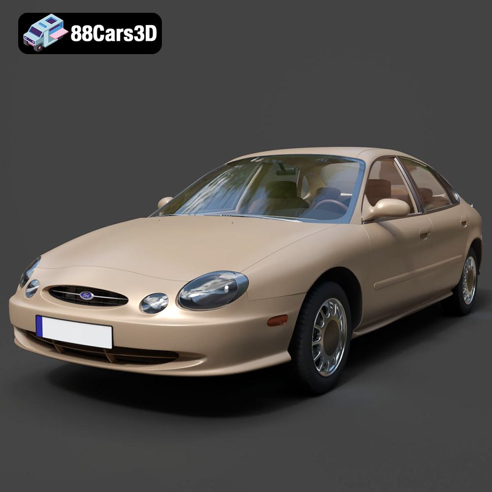
Texture: Yes | Material: Yes
Download the highly detailed, game-ready Ford Taurus 1996 3D Model. Features revolutionary oval exterior styling, detailed interior, and accurate chassis geometry. Includes .blend, .fbx, .obj, .glb, .stl, .ply, .unreal, and .max formats for game development, AR/VR, and rendering.
Price: $161.00
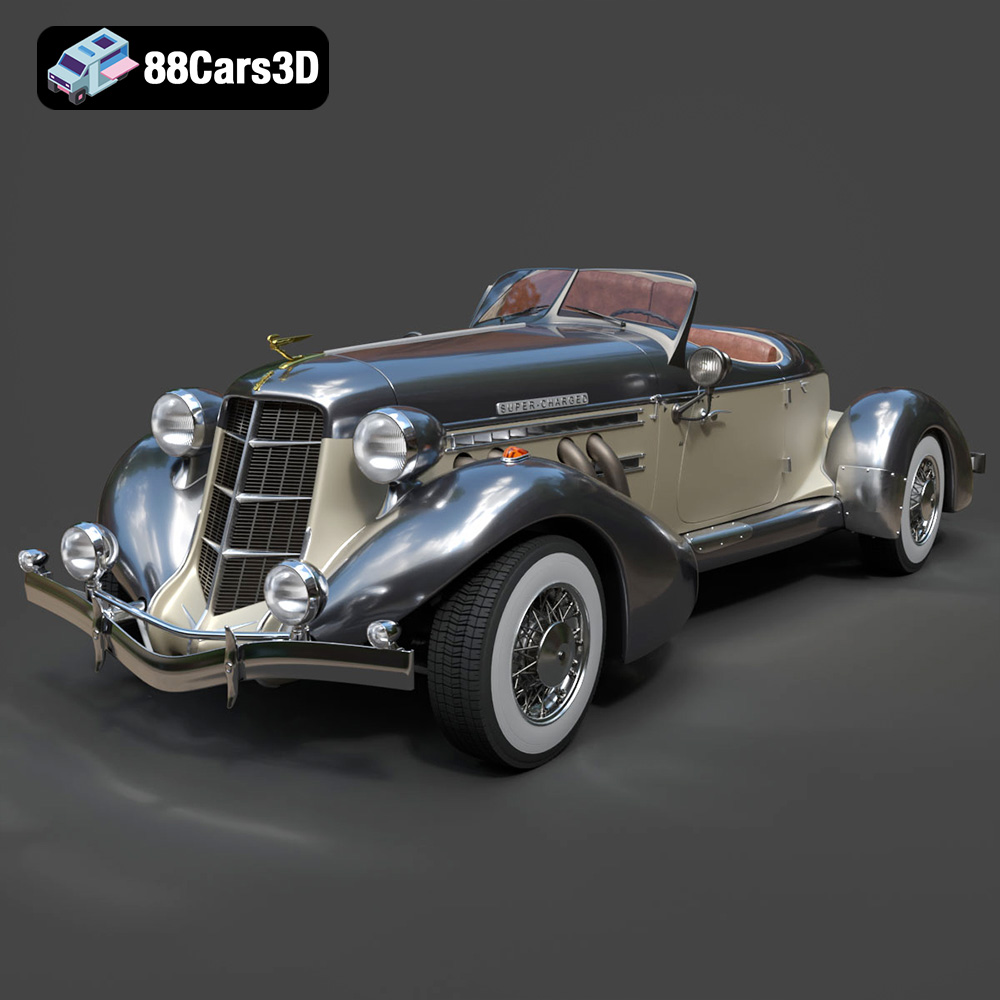
Texture: Yes | Material: Yes
Download the highly detailed, game-ready Auburn Speedster 851 3D Model. Features iconic boat-tail rear styling, exposed chrome exhaust pipes, and an authentic Art Deco cockpit. Includes .blend, .fbx, .obj, .glb, .stl, .ply, .unreal, and .max formats for game development, AR/VR, and rendering.
Price: $199.50
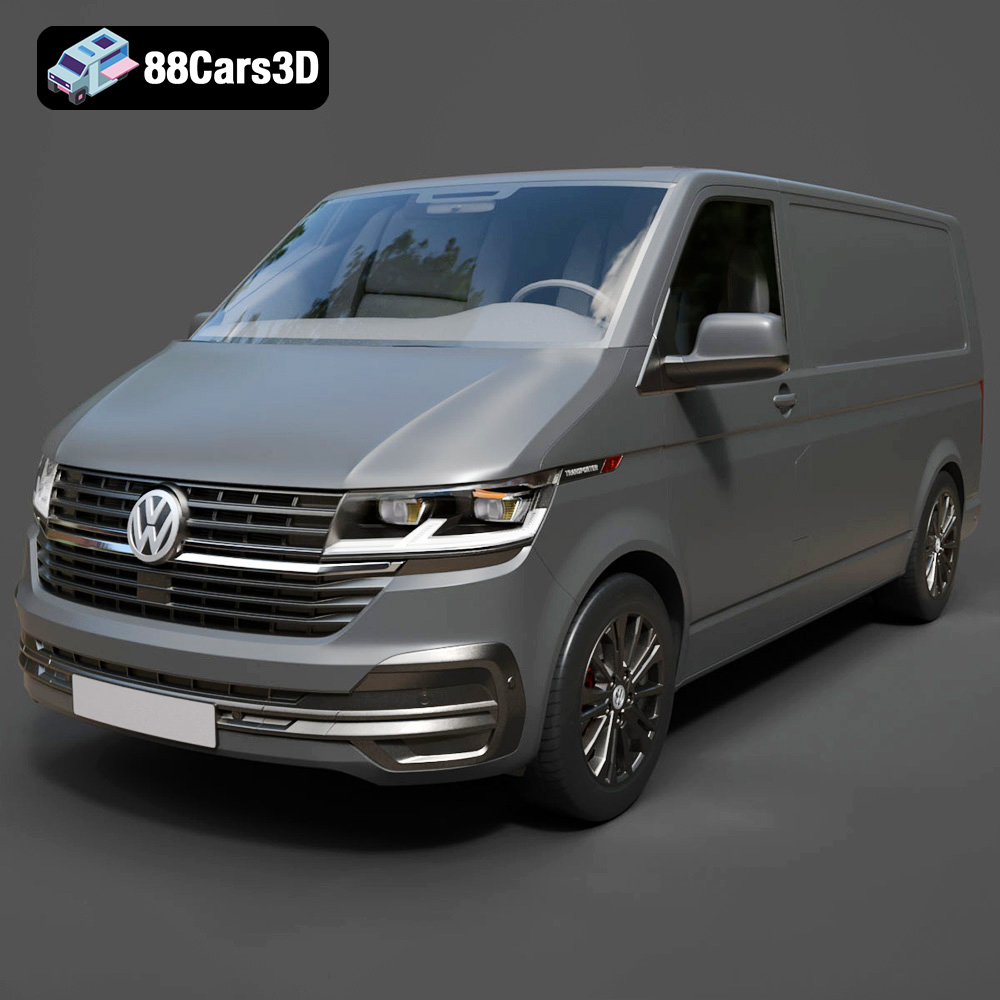
Texture: Yes | Material: Yes
Download the highly detailed, game-ready Volkswagen Transporter T6.1 Panelvan 2020 3D Model. Features authentic front grille styling, commercial panelvan body contours, and an accurately modeled cabin interior. Includes .blend, .fbx, .obj, .glb, .stl, .ply, .unreal, and .max formats for game development, AR/VR, and rendering.
Price: $264.50
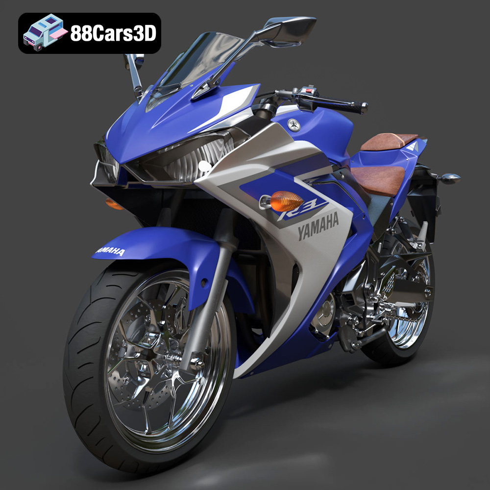
Texture: Yes | Material: Yes
Download the highly detailed, game-ready Yamaha YZF R3 2015 3D Model. Features aerodynamic supersport fairings, detailed parallel-twin engine, and high-fidelity cockpit. Includes .blend, .fbx, .obj, .glb, .stl, .ply, .unreal, and .max formats for game development, AR/VR, and rendering.
Price: $227.00
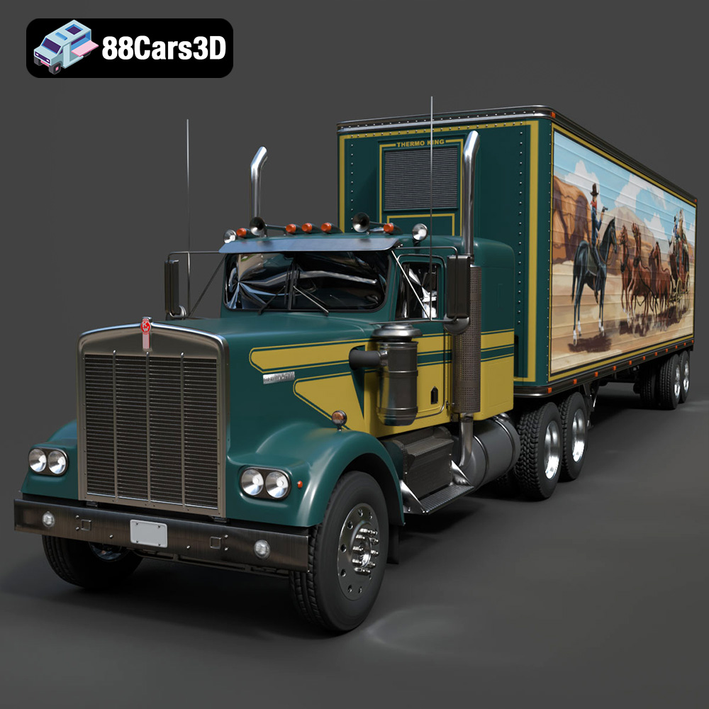
Texture: Yes | Material: Yes
Download the highly detailed, game-ready Kenworth W900 1974 3D Model. Features classic long-nose hood styling, detailed chrome exhaust stacks, and realistic dual tandem axles. Includes .blend, .fbx, .obj, .glb, .stl, .ply, .unreal, and .max formats for game development, AR/VR, and rendering.
Price: $299.50
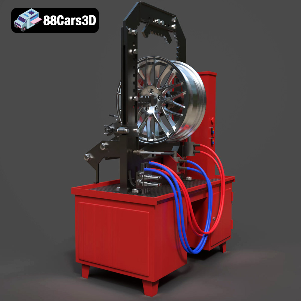
Texture: Yes | Material: Yes
Download the highly detailed, game-ready Stand for Straightening Alloy Wheels 3D Model. Features heavy-duty hydraulic press components, integrated lathe system, and realistic workshop controls. Includes .blend, .fbx, .obj, .glb, .stl, .ply, .unreal, and .max formats for game development, AR/VR, and rendering.
Price: $147.99
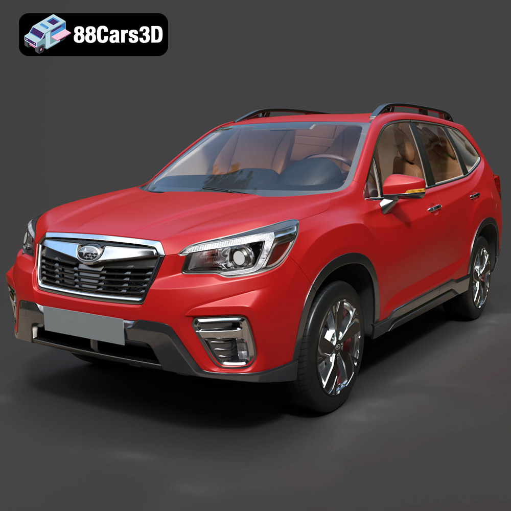
Texture: Yes | Material: Yes
Download the highly detailed, game-ready Subaru Forester 2019 3D Model. Features authentic crossover styling, detailed interior, and accurate exterior geometry. Includes .blend, .fbx, .obj, .glb, .stl, .ply, .unreal, and .max formats for game development, AR/VR, and rendering.
Price: $245.50
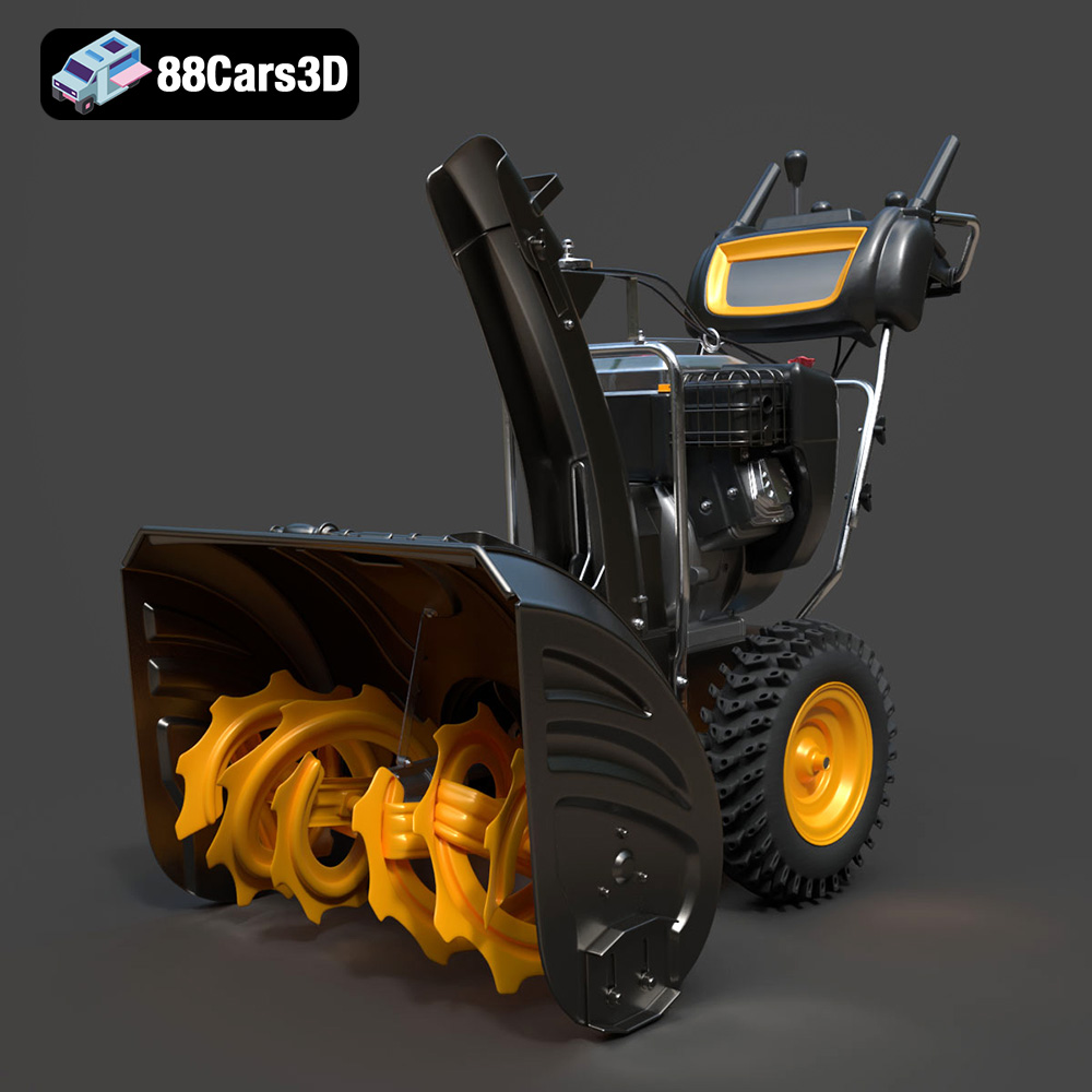
Texture: Yes | Material: Yes
Download the highly detailed, game-ready Husqvarna Snow Plow 3D Model. Features heavy-duty front plow blade, robust chassis, and realistic mechanical controls. Includes .blend, .fbx, .obj, .glb, .stl, .ply, .unreal, and .max formats for game development, AR/VR, and rendering.
Price: $145.50
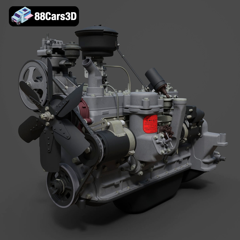
Texture: Yes | Material: Yes
Download the highly detailed, game-ready ZIL-157 Engine 3D Model. Features authentic inline-6 block geometry, intake and exhaust manifolds, and detailed carburetor assembly. Includes .blend, .fbx, .obj, .glb, .stl, .ply, .unreal, and .max formats for game development, AR/VR, and rendering.
Price: $203.50

Texture: Yes | Material: Yes
Download the highly detailed, game-ready Audi Q4 e-tron 2021 3D Model. Features sleek electric SUV styling, signature Singleframe grille, and detailed Matrix LED lighting. Includes .blend, .fbx, .obj, .glb, .stl, .ply, .unreal, and .max formats for game development, AR/VR, and rendering.
Price: $299.50
