
The sleek lines, reflective surfaces, and intricate details of a modern automobile present one of the most compelling challenges and rewarding achievements in 3D modeling. For 3D artists, game developers, automotive designers, and visualization professionals, mastering the art of creating photorealistic 3D car models is a cornerstone skill. This comprehensive guide delves deep into the world of hard surface modeling, specifically leveraging the power and flexibility of Blender, to craft stunning automotive assets. We’ll explore everything from foundational topology principles to advanced rendering techniques, ensuring your creations meet the demanding standards of professional applications, whether for high-fidelity renders, interactive game experiences, or cutting-edge AR/VR simulations.
Creating a truly convincing 3D car model isn’t just about recreating shapes; it’s about understanding the nuances of surface continuity, light reflection, and material behavior. This article will equip you with the technical knowledge and practical workflows necessary to tackle these complexities. From ensuring clean, animatable topology that captures every curve to crafting physically accurate materials that react realistically to light, we will meticulously unpack the processes involved. You’ll learn how to optimize your models for diverse platforms, prepare them for stunning visualizations, and ensure they are ready for production pipelines, much like the meticulously crafted 3D car models available on platforms like 88cars3d.com.
At the heart of every exceptional 3D car model lies impeccable topology and intelligent edge flow. These aren’t merely technical terms; they are the bedrock upon which realism, deformability, and optimization are built. Automotive surfaces are characterized by their vast, often subtly curved panels, sharp creases, and complex intersections. Achieving a photorealistic appearance hinges on how these surfaces interact with light, and this interaction is directly dictated by the underlying mesh structure. Poor topology can lead to pinching, unsightly reflections, and difficulties in UV mapping or animation. A clean, quad-based mesh is paramount, as it allows for predictable subdivision, crucial for capturing the smooth, continuous surfaces of a vehicle.
The concept of edge flow refers to the direction and continuity of polygon edges across the model. For automotive designs, maintaining edge loops that follow the natural contours of the car – around headlights, wheel wells, door seams, and body lines – is critical. This ensures that when subdivision surfaces are applied, the mesh smooths out gracefully, preventing unwanted bumps or dips. Proper edge flow also simplifies selecting components, making future modifications and detailing much more efficient. It’s a meticulous process that demands patience and a keen eye for subtle curves, but the payoff is a model that holds up under close scrutiny and various lighting conditions.
Blender, like most professional 3D software, thrives on quad-based geometry (four-sided polygons) for organic and hard-surface modeling, especially when subdivision surfaces are involved. Subdivision surface modifiers, such as Blender’s Subdivision Surface modifier, take a lower-resolution base mesh and mathematically smooth it by dividing each polygon into smaller ones, creating a high-resolution, curved surface. Quads ensure that this smoothing process is consistent and predictable, avoiding the artifacts and pinching often associated with triangles or N-gons in such workflows. For a 3D car model, this translates to perfectly smooth body panels that reflect light without distortion, mimicking real-world automotive finishes.
The way light bounces off a car’s surface is heavily influenced by its curvature. Imperfections in topology, even tiny ones, can become glaringly obvious as unsightly “dents” or “waves” in reflections. To counteract this, artists must meticulously sculpt the edge flow to guide the reflections smoothly across the car’s body. This often involves creating “control loops” – extra edge loops placed close to sharp creases or around holes – to maintain definition when subdivision is applied. For example, a crisp edge along a car’s fender requires several tightly spaced edge loops running parallel to that edge. These loops act as a “cage” that defines the sharp feature while the surrounding broader loops control the overall curvature. Furthermore, if the model is intended for animation (e.g., doors opening, wheels turning), a clean and logical edge flow facilitates rigging and deformation without collapsing or tearing the mesh.
Automotive design is replete with precise panel gaps and razor-sharp edges that define its aesthetic. Replicating these in 3D requires specific techniques. For panel gaps, a common approach involves creating separate mesh pieces for each panel. This allows for precise control over the gap width and ensures that each panel’s surface is independently smooth. For the edges that define these gaps, a combination of the Bevel modifier (with specific segment and profile settings) and careful edge weighting can create the desired sharpness when subdivision is applied. Alternatively, manual edge creasing or adding support loops very close to the edge can achieve similar results. The goal is to achieve a crisp, defined edge that doesn’t “melt” away when subdivided, while also ensuring the surrounding surfaces remain perfectly smooth. Achieving consistent gap widths and sharp details across the entire vehicle is a hallmark of professional 3D car modeling.
Blender offers a robust suite of tools perfectly suited for hard surface modeling, allowing artists to create intricate and precise automotive geometries. The key lies in understanding how to combine these tools effectively, often in a non-destructive workflow, to build complex shapes while maintaining flexibility for later adjustments. From foundational operations like extrusion and inset to powerful modifiers that automate complex tasks, Blender provides the means to tackle the most demanding car modeling projects. Proficiency with these tools not only speeds up the modeling process but also contributes significantly to the quality and technical integrity of the final 3D car model.
A non-destructive workflow is particularly valuable in automotive design, where subtle adjustments to curves or panel designs might be required late in the production cycle. By utilizing modifiers, which can be stacked and reordered, artists can experiment with different parameters without permanently altering the base mesh. This iterative approach allows for greater precision and efficiency, enabling the creation of high-quality assets that meet strict technical specifications. Understanding when and how to apply these tools, and when to commit them to the mesh, is a crucial skill for any hard surface artist.
Blender’s modifier stack is a game-changer for hard surface modeling. The Bevel modifier is indispensable for adding realistic fillets and chamfers to sharp edges, which are crucial for catching reflections convincingly. The Solidify modifier is excellent for giving thin panels realistic thickness, essential for door panels, hoods, and other body components. The Mirror modifier allows artists to model only half of the car, automatically mirroring the changes to the other side, ensuring perfect symmetry and saving countless hours. Other modifiers like Array, Boolean, and Shrinkwrap also play vital roles in creating complex mechanical components or conforming meshes to reference geometry. The power of these modifiers lies in their ability to be tweaked, enabled, disabled, or even removed at any stage of the modeling process without destroying the underlying mesh, facilitating rapid iteration and refinement.
Beyond modifiers, Blender’s core modeling tools form the backbone of hard surface creation. Extrude (E) is fundamental for pulling out new geometry from faces, edges, or vertices, forming the basis of many car parts. Inset (I) creates a new face inside a selected face, perfect for defining headlight housings or window frames. Loop Cut and Slide (Ctrl+R) adds new edge loops across a mesh, vital for refining topology, adding detail, and controlling subdivision surfaces. Slide Edge (GG) allows edges to be moved along existing geometry without changing the overall shape, invaluable for cleaning up spacing or adjusting edge flow. Combined with tools like Merge (M), Dissolve (X), and Rip (V), these form a powerful toolkit for precise, vertex-level control over the car’s geometry. Understanding how and when to use each of these tools effectively is key to efficient and clean hard surface modeling.
Even with perfect topology, shading artifacts can appear on hard surface models, especially on low-poly meshes or those with sharp angles that receive subdivision. This is where Custom Normals and Weighted Normals become critical. Normals dictate how light interacts with a surface, defining its perceived smoothness or sharpness. Weighted Normals, often applied via a modifier in Blender, calculate the average normal direction of faces, giving more weight to larger faces. This can result in incredibly smooth-looking surfaces even with relatively lower polygon counts, preventing visual discontinuities and achieving better consistency in reflections. For complex automotive surfaces, especially those with both sharp edges and broad, smooth areas, correct normal orientation and weighting are paramount for achieving a professional, artifact-free appearance. This is particularly important for game assets and real-time visualization, where every optimization counts. For more information, consult the Blender 4.4 manual section on Normals.
UV mapping is often perceived as a tedious yet unavoidable step in the 3D pipeline, but for complex subjects like 3D car models, it’s an art form unto itself. Without a well-thought-out UV layout, even the most exquisitely modeled car will fall flat when it comes to texturing. UVs (U and V being the axes on a 2D texture map) essentially flatten your 3D model’s surfaces onto a 2D plane, allowing you to paint or apply textures that wrap seamlessly around the object. For the expansive, often curved panels of a car, strategic seam placement and efficient use of texture space are crucial for achieving photorealistic results without visible stretching, seams, or resolution issues.
The goal of efficient UV mapping for automotive models is to minimize seams, avoid distortion, and maximize texel density. Texel density refers to the number of pixels per unit of 3D space. Achieving a consistent texel density across all visible parts of the car ensures that textures appear uniform in resolution and detail. This is particularly important for high-resolution renders and close-up shots where inconsistencies would be immediately apparent. A well-prepared UV map not only enhances visual quality but also streamlines the texturing process, making it more intuitive and less prone to errors.
The vast, smooth surfaces of a car’s body panels demand careful UV unwrapping. A common strategy is to treat each major panel (hood, roof, doors, fenders) as a separate UV island. Seams should be placed in areas that are naturally hidden or follow existing panel lines, minimizing their visibility. For example, the underside of a door or the edge where a fender meets the chassis are ideal places for seams. Blender’s UV editor provides tools like “Mark Seam” and various unwrapping methods (e.g., Smart UV Project, Cube Projection, Follow Active Quads) to help with this process. The “Follow Active Quads” method, in particular, is excellent for unwrapping strips of quads with a consistent flow, which is often the case for automotive body lines, creating neat, rectangular UV islands that are easy to texture.
One of the biggest challenges in UV mapping car models is dealing with highly curved surfaces without introducing texture stretching or visible seams. While seams are often unavoidable, strategic placement can make them almost invisible. For complex curves like those on a car’s front or rear bumper, a cylindrical or spherical projection might be a good starting point, followed by manual adjustment and pinning in the UV editor to minimize distortion. For more organic or complex curvatures, a ‘cut and flatten’ approach, where seams are carefully placed to allow the surface to unfold naturally, is essential. Regularly checking the UV distortion with Blender’s UV stretching overlay (accessed in the UV Editor’s View menu) is crucial to identify and correct problem areas before texturing begins.
Once individual UV islands are unwrapped, they need to be efficiently packed into a 0-1 UV space (the square area that represents your texture map). Blender’s UV packing algorithms can automatically arrange islands, but manual refinement is often necessary to maximize space utilization. The goal is to leave as little empty space as possible while maintaining adequate padding between islands to prevent texture bleed. More importantly, consistent texel density across all islands ensures visual uniformity. If a small, insignificant part has a higher texel density than a large, prominent body panel, you’re wasting valuable texture resolution. Tools like UV squares and manual scaling in the UV editor allow you to normalize texel density. For game assets, consolidating multiple car components into a single texture atlas further optimizes performance by reducing draw calls, making the model more efficient for real-time engines.
The realism of a 3D car model is ultimately defined by its materials. Physically Based Rendering (PBR) has revolutionized how we approach material creation, ensuring that digital surfaces react to light in a way that closely mimics their real-world counterparts. For automotive applications, this means meticulously crafting materials for everything from gleaming car paint to textured tires, reflective chrome, and transparent glass. Understanding the core principles of PBR and how to build complex shading networks in Blender’s Cycles or Eevee render engines is paramount for achieving a truly photorealistic vehicle.
PBR workflows are based on physically accurate properties: Albedo/Base Color, Metallic, Roughness, Normal, and optionally Specular and Ambient Occlusion. These maps work in concert to define how light is absorbed, reflected, and scattered by a surface. The beauty of PBR is its predictability; once materials are correctly set up, they will look consistent under varying lighting conditions. This consistency is vital for automotive visualization, where vehicles might be placed in studio environments, outdoor scenes, or even interactive real-time applications, all demanding a high degree of fidelity and accuracy.
At its core, PBR materials distinguish between dielectric (non-metallic) and metallic surfaces. Dielectric materials (like plastic, rubber, painted surfaces) have a base color and reflect light at varying degrees of roughness, while metallic materials (like chrome, aluminum) have their base color influenced by their reflective properties, appearing reflective even at grazing angles. The Roughness map is critical, defining how spread out reflections are – a smooth surface (low roughness) will have sharp, clear reflections, while a rougher surface will have diffuse, blurry reflections. The Normal map simulates fine surface detail without adding actual geometry, crucial for adding subtle textures to tires or intricate patterns to interior fabrics. Correctly calibrating these values and using high-quality texture maps are fundamental to PBR success. Blender’s Principled BSDF shader encapsulates many PBR properties into a single, intuitive node, simplifying the process.
Automotive paint is one of the most complex PBR materials to replicate due to its multi-layered nature. A typical car paint shader in Blender would involve several components:
Combining these elements within a shader network allows for incredible realism, capturing the depth and complexity of real car finishes.
Beyond paint, other car materials demand equally meticulous attention:
Each material requires careful balancing of PBR parameters and high-quality texture inputs to contribute to the overall photorealism of the 3D car model.
A beautifully detailed 3D car model destined for high-resolution renders may be far too heavy for a real-time game engine or an AR/VR experience. Optimization is a critical phase in the 3D pipeline, transforming a high-poly, render-ready asset into a performant model suitable for diverse applications. This involves a strategic reduction of polygon count, smart texture management, and careful preparation to ensure the model looks great while running smoothly on target hardware. Whether you’re supplying models to a marketplace like 88cars3d.com or integrating them into your own projects, understanding these optimization techniques is key to broadening their usability.
The core principle of optimization is to achieve the best possible visual quality with the lowest computational cost. This isn’t about compromising quality but about intelligently managing resources. Different applications have different constraints – game engines prioritize framerate, AR/VR demands extremely low latency, and 3D printing requires mesh integrity. Tailoring your optimization strategy to the specific end-use case is crucial for success.
For game development (Unity, Unreal Engine), optimization focuses on maintaining high framerates.
AR/VR applications have even tighter performance constraints than traditional games due to the need for high framerates (often 90fps or more per eye) to prevent motion sickness.
3D printing introduces a unique set of optimization requirements focused on physical integrity.
These rigorous checks ensure that the 3D printer can interpret the model correctly and produce a physically sound object.
After meticulously modeling, UV mapping, and texturing your 3D car, the final step is to bring it to life through high-quality rendering and strategic post-processing. This is where your hard work culminates in stunning visuals that can command attention in portfolios, marketing materials, or professional presentations. Blender’s Cycles and Eevee render engines offer powerful capabilities, from physically accurate global illumination to real-time feedback. Mastering the art of lighting, camera composition, and atmospheric effects, followed by careful compositing, transforms a static 3D model into a captivating image or animation.
Rendering is more than just hitting the “render” button; it’s about art direction. Just like a professional photographer sets up a shoot, a 3D artist must choreograph the lighting, camera angle, and environment to highlight the car’s best features and convey a specific mood. Post-processing then acts as the final polish, enhancing colors, adding atmospheric depth, and correcting any minor imperfections to achieve a truly professional finish that makes your 3D car model stand out, whether for a client showcase or a product listing on 88cars3d.com.
Effective lighting is the single most important factor in achieving photorealistic car renders.
Just like a real camera, Blender’s virtual camera offers settings that profoundly impact the final image.
Post-processing is the final crucial step to elevate your renders from good to exceptional.
The goal is to enhance, not create. Post-processing should subtly refine the render, giving it that final polished, professional touch.
Creating high-quality 3D car models in Blender is a journey that demands precision, technical understanding, and artistic vision. From the foundational principles of clean topology and efficient UV mapping to the intricate details of PBR material creation and the final flourish of expert rendering and post-processing, each stage plays a vital role in bringing a virtual vehicle to life. Mastering Blender’s powerful toolset, including its modifiers, modeling functions, and advanced shading capabilities, empowers artists to tackle even the most challenging automotive designs with confidence.
The skills honed in hard surface modeling for cars are incredibly versatile, applicable across a wide spectrum of industries—from captivating advertising visuals and immersive game environments to detailed automotive design prototypes and cutting-edge AR/VR experiences. By adhering to industry best practices in optimization, your models will not only look exceptional but will also perform flawlessly across various platforms. Remember, continuous learning, diligent practice, and an analytical eye for real-world details are your greatest assets. Whether you’re building a portfolio piece or preparing models for marketplaces like 88cars3d.com, applying these comprehensive techniques will ensure your 3D car models stand out as professional, visually stunning, and technically robust assets.
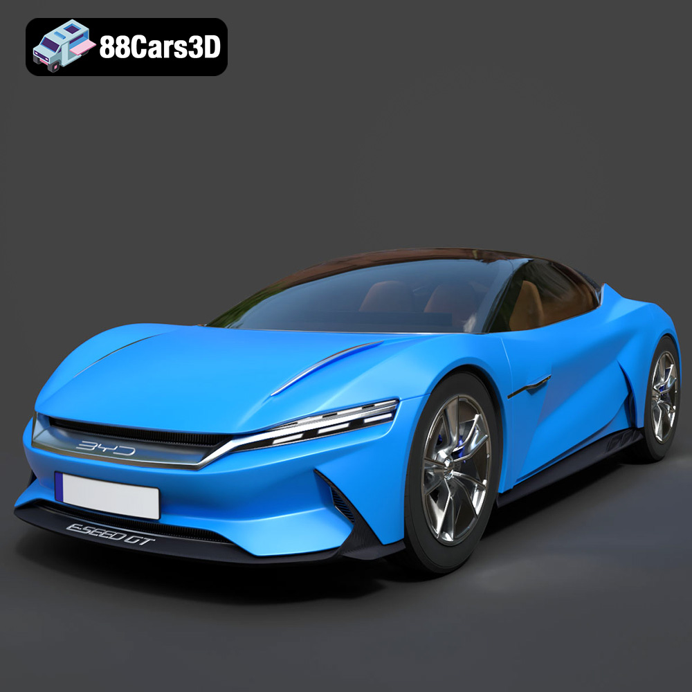
Texture: Yes | Material: Yes
Download the highly detailed, game-ready BYD e-SEED GT 2019 3D Model. Features futuristic gull-wing doors, sleek aerodynamic electric supercar silhouette, and detailed LED light strips. Includes .blend, .fbx, .obj, .glb, .stl, .ply, .unreal, and .max formats for game development, AR/VR, and rendering.
Price: $194.50
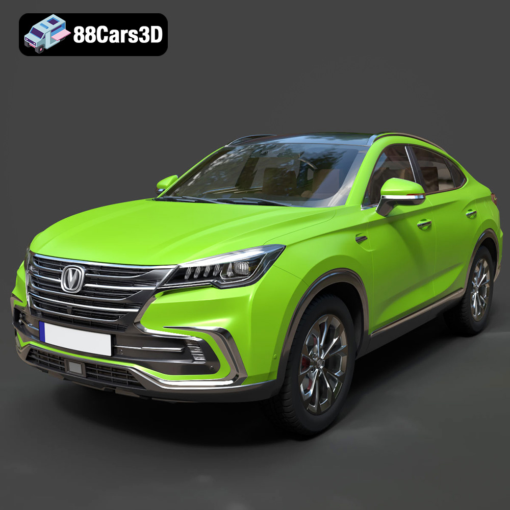
Texture: Yes | Material: Yes
Download the highly detailed, game-ready Changan CS85 Coupe 2019 3D Model. Features sleek fastback SUV styling, detailed front grille, and realistic lighting. Includes .blend, .fbx, .obj, .glb, .stl, .ply, .unreal, and .max formats for game development, AR/VR, and rendering.
Price: $275.00
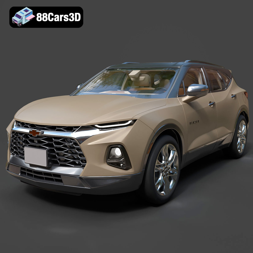
Texture: Yes | Material: Yes
Download the highly detailed, game-ready Chevrolet Blazer RS 2019 3D Model. Features bold blacked-out RS trim styling, sharp LED lighting signatures, and detailed interior geometry. Includes .blend, .fbx, .obj, .glb, .stl, .ply, .unreal, and .max formats for game development, AR/VR, and rendering.
Price: $132.50
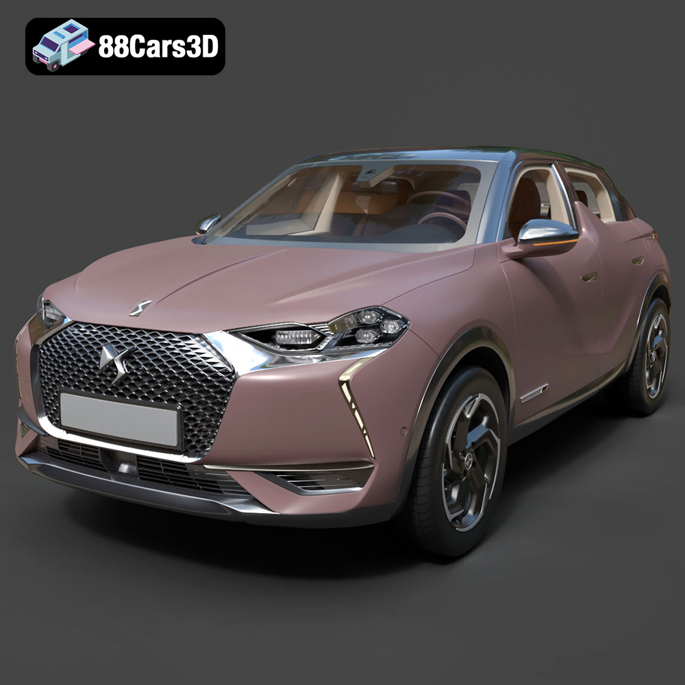
Texture: Yes | Material: Yes
Download the highly detailed, game-ready Citroen DS3 Crossback 2018 3D Model. Features signature diamond grid grille, flush door handles, and distinctive shark-fin B-pillars. Includes .blend, .fbx, .obj, .glb, .stl, .ply, .unreal, and .max formats for game development, AR/VR, and rendering.
Price: $276.00
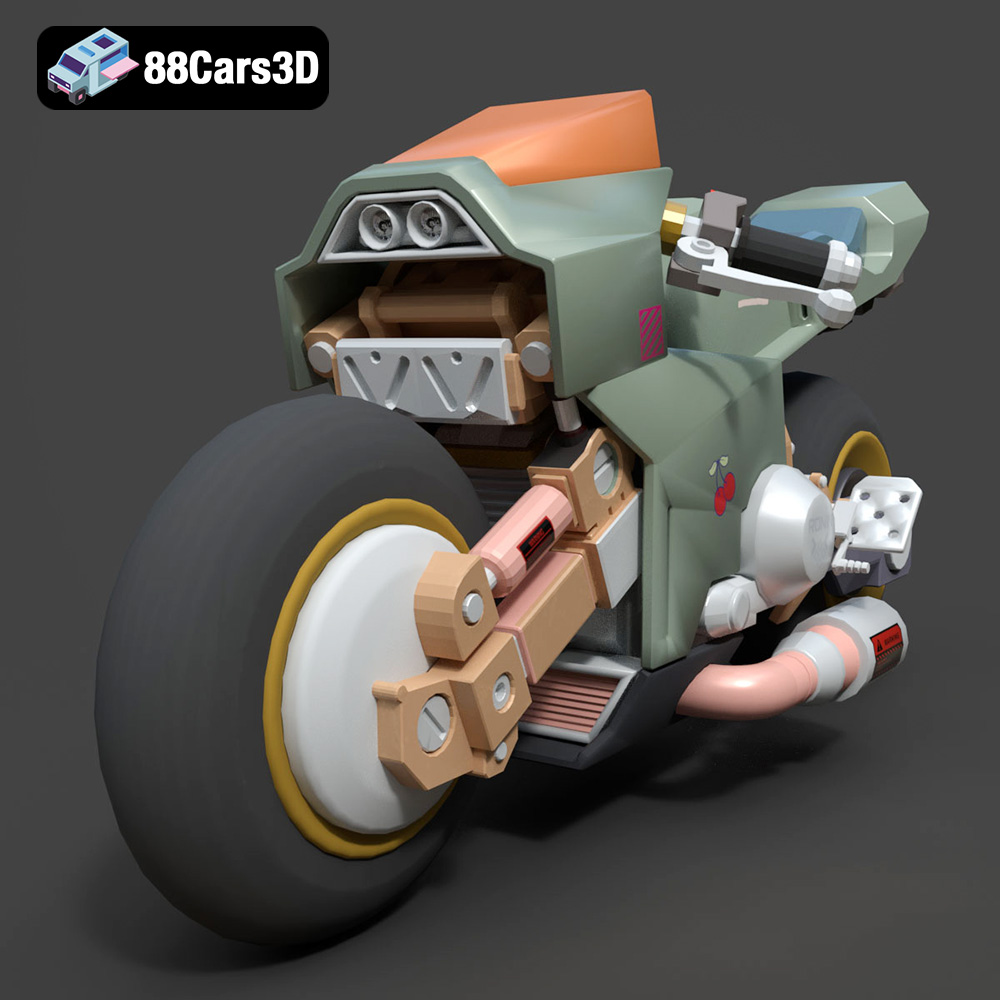
Texture: Yes | Material: Yes
Download the highly detailed, game-ready Cyber Bike 02 3D Model. Features futuristic sci-fi aesthetic, glowing LED lighting elements, and sleek aerodynamic paneling. Includes .blend, .fbx, .obj, .glb, .stl, .ply, .unreal, and .max formats for game development, AR/VR, and rendering.
Price: $99.99
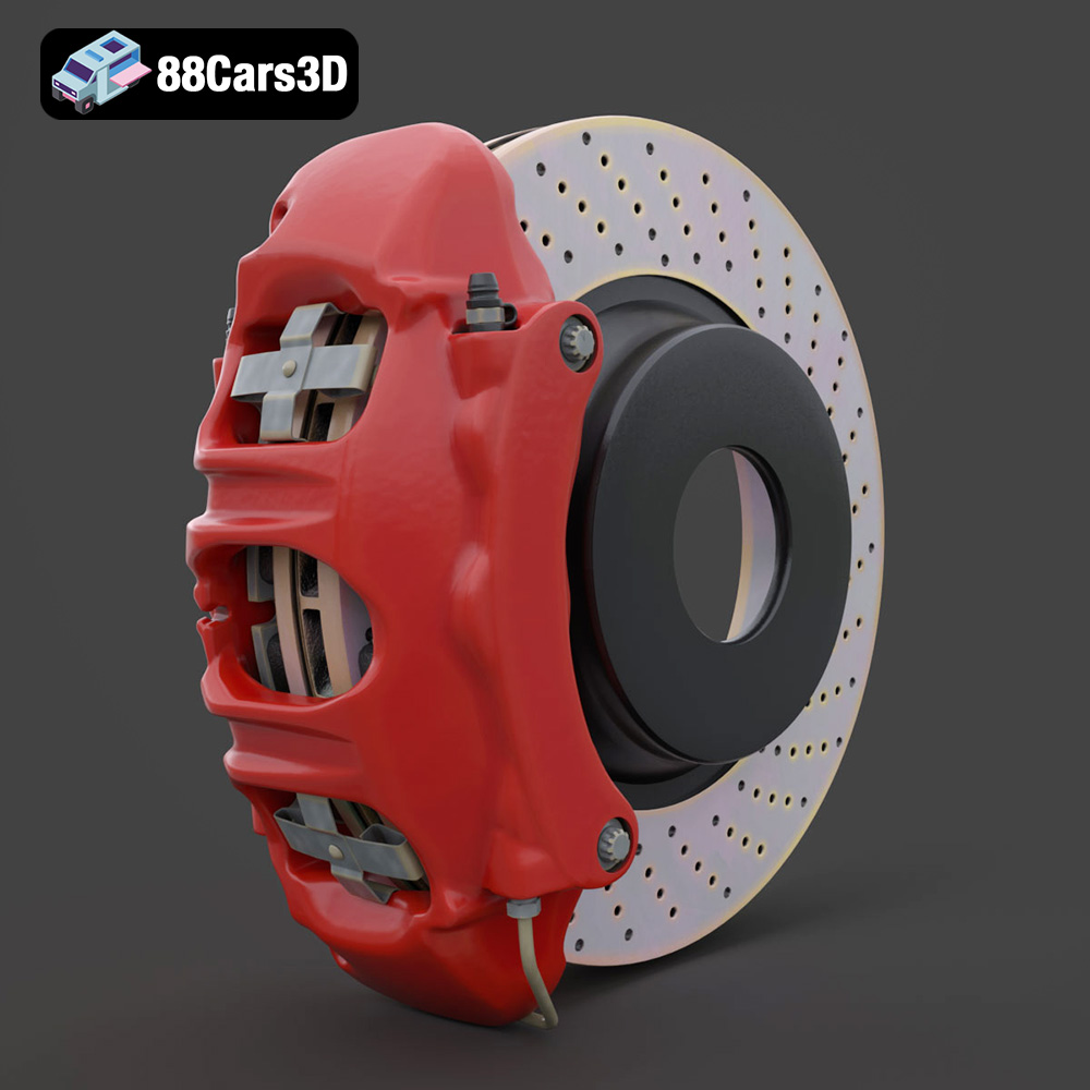
Texture: Yes | Material: Yes
Download the highly detailed, game-ready Brake Assembly 3D Model. Features a ventilated brake rotor, multi-piston caliper, and precision mounting hardware. Includes .blend, .fbx, .obj, .glb, .stl, .ply, .unreal, and .max formats for game development, AR/VR, and rendering.
Price: $104.99
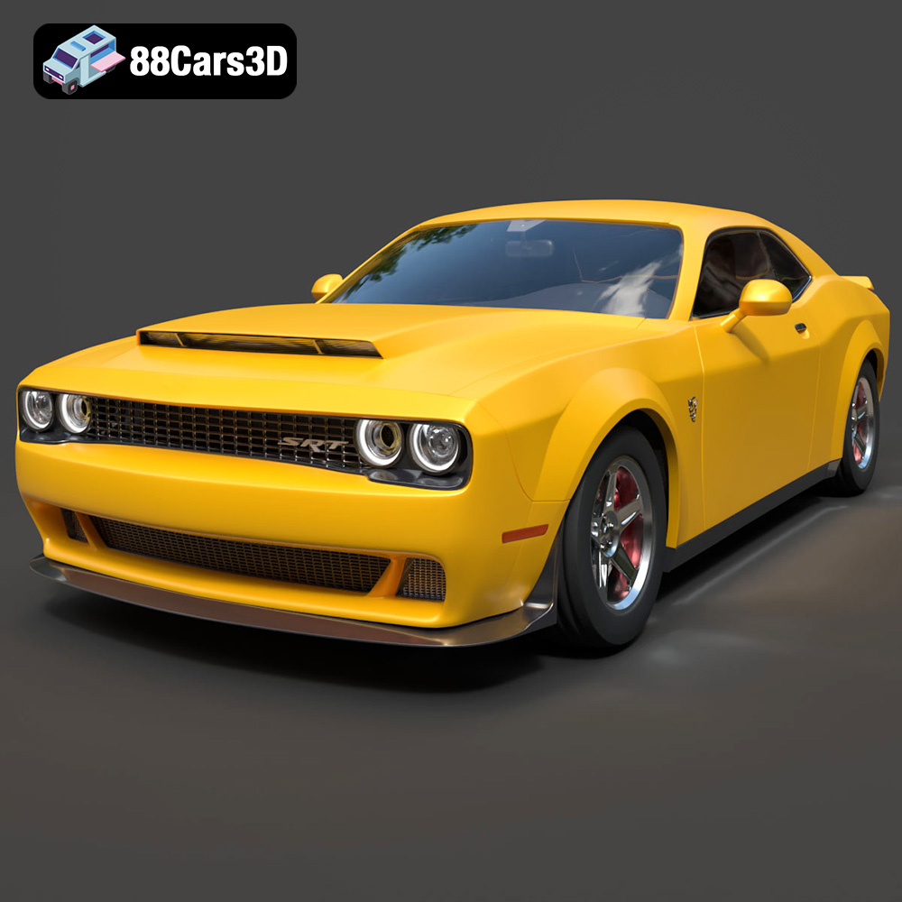
Texture: Yes | Material: Yes
Download the highly detailed, game-ready Dodge Demon SRT 3D Model. Features aggressive widebody styling, supercharged HEMI V8 details, and high-fidelity exterior details. Includes .blend, .fbx, .obj, .glb, .stl, .ply, .unreal, and .max formats for game development, AR/VR, and rendering.
Price: $279.99
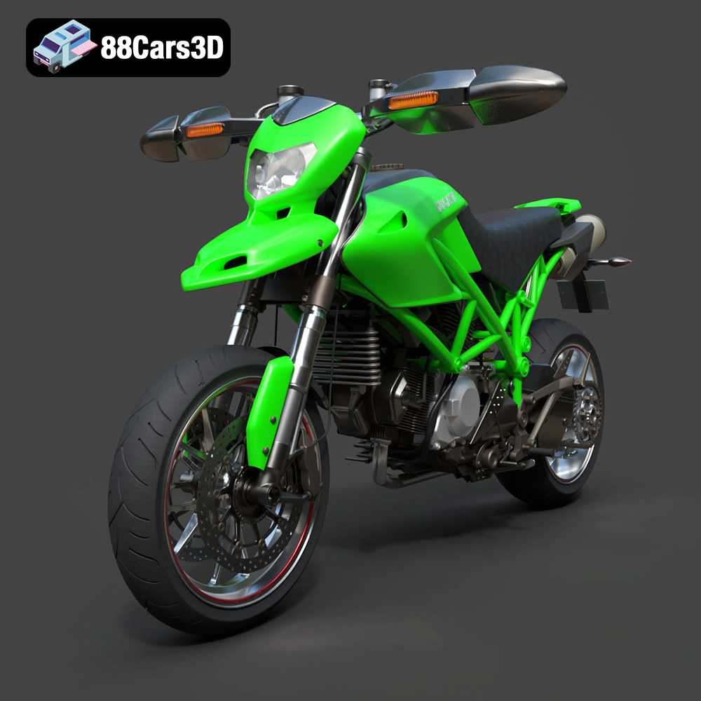
Texture: Yes | Material: Yes
Download the highly detailed, game-ready Ducati Hypermotard 1100 EVO 2011 3D Model. Features an iconic Desmodromic L-twin engine, trellis frame, and signature under-seat exhaust design. Includes .blend, .fbx, .obj, .glb, .stl, .ply, .unreal, and .max formats for game development, AR/VR, and rendering.
Price: $197.99
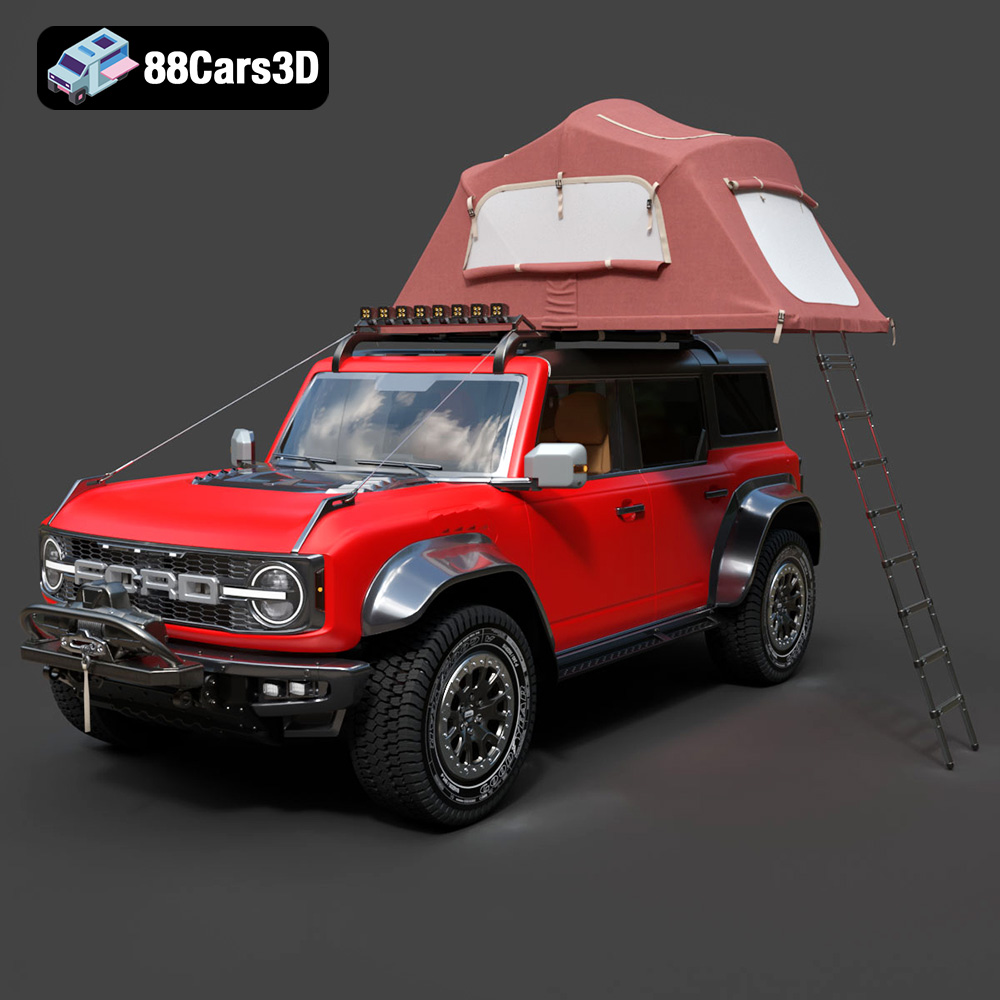
Texture: Yes | Material: Yes
Download the highly detailed, game-ready Ford Bronco Raptor Rooftop Tent 3D Model. Features aggressive widebody styling, detailed off-road suspension, and a fully modelled overland rooftop tent. Includes .blend, .fbx, .obj, .glb, .stl, .ply, .unreal, and .max formats for game development, AR/VR, and rendering.
Price: $299.50
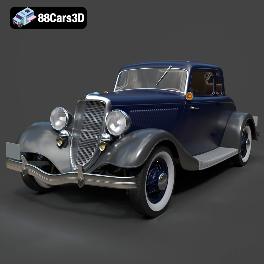
Texture: Yes | Material: Yes
Download the highly detailed, game-ready Ford Coupe 1934 3D Model. Features sweeping fenders, iconic 1930s grille design, and authentic vintage proportions. Includes .blend, .fbx, .obj, .glb, .stl, .ply, .unreal, and .max formats for game development, AR/VR, and rendering.
Price: $203.00
