
The world of 3D modeling for automotive design, rendering, and game asset development is a realm where precision, efficiency, and aesthetic appeal converge. At the heart of achieving truly professional results, especially for intricate subjects like cars, lies a critical process often overlooked by beginners but revered by veterans: **retopology**. Whether you’re aiming for a stunning cinematic render, an optimized game asset, or a precisely crafted model for AR/VR experiences, a clean, well-structured mesh is non-negotiable. This comprehensive guide will delve deep into the art and science of retopology within Blender, equipping you with the knowledge and workflows to transform high-detail sculpts into production-ready 3D car models.
Retopology is more than just reducing polygon count; it’s about reconstructing the surface of a high-resolution mesh with a new, optimized, and animation-friendly low-resolution mesh. This process ensures ideal edge flow, uniform polygon distribution (primarily quads), and a cleaner foundation for UV mapping, texturing, and rigging. Without proper retopology, even the most beautifully sculpted car can become a technical nightmare, leading to deformation issues, inefficient rendering, and bloated file sizes unsuitable for real-time applications. Join us as we navigate the essential Blender tools and techniques that will elevate your automotive 3D modeling skills to the next level, making your creations perfectly suited for platforms like 88cars3d.com and beyond.
The foundation of any high-quality 3D car model lies in its topology – the arrangement of vertices, edges, and faces that define the object’s surface. For automotive assets, which are characterized by sleek curves, sharp creases, and complex mechanical parts, an impeccable topology with intelligent edge flow is paramount. Bad topology can lead to pinching, shading artifacts, and difficulties in UV mapping and deformation. Therefore, before even touching retopology tools, it’s crucial to understand the principles that dictate a “good” mesh.
In 3D modeling, quadrilaterals (quads) are the preferred face type for most organic and hard-surface modeling, particularly when subdivision surface modifiers are involved. Quads subdivide predictably, maintaining smooth curves and surfaces. Triangles (tris) can be acceptable in flat, non-deforming areas or where polygon reduction is critical, but they can cause pinching and unpredictable subdivision patterns if not managed carefully. N-gons (faces with more than four vertices) are generally to be avoided in subdivision-ready meshes as they can lead to severe shading issues and complex, non-uniform triangulation upon export. For automotive models, which rely heavily on smooth, continuous surfaces, maintaining a predominantly quad-based topology is a golden rule. This ensures that reflections along the car’s body panels remain pristine and free from unsightly artifacts, which is vital for photorealistic rendering.
Optimal edge flow means that the edges of your mesh follow the natural contours and prominent features of your model. For a 3D car model, this translates to edge loops running smoothly along the body lines, around wheel wells, headlights, door seams, and over the hood and roof. These edge loops act as guides, dictating how the surface will deform and how light will reflect. Proper edge flow is especially critical around areas that will eventually be cut (like panel gaps) or receive high-resolution detail. When planning your retopology, visualize these primary contours first. Ensure that areas requiring sharp creases (e.g., fender edges) have a few tight edge loops running parallel to reinforce them, while areas needing smooth transitions (e.g., hood curvature) have evenly spaced quads that flow naturally. This meticulous planning in edge flow not only makes the model aesthetically pleasing but also simplifies future modifications and ensures that applied modifiers like Subdivision Surface perform optimally.
Blender offers a robust set of tools that can be leveraged for efficient and precise retopology. While the process often requires a degree of manual intervention, these tools significantly streamline the workflow, allowing artists to create clean, optimized meshes from high-resolution sculpts or scanned data. Understanding how to use these effectively is key to achieving professional results in automotive 3D modeling.
One of the most fundamental setups for retopology in Blender involves the snapping tools. To begin, ensure your high-resolution model is visible in the viewport. Then, create a new mesh object (e.g., a plane) that will serve as your retopology canvas. With this new object selected and in Edit Mode, activate “Snapping” (Shift + Tab) and set its type to “Face” (or “Face Project” for more advanced scenarios). Critically, also enable “Project Individual Elements” and set the “Snap With” option to “Active” or “Center” depending on your preference. This configuration ensures that as you model your low-poly mesh, its vertices will snap directly onto the surface of your high-poly reference, maintaining accurate surface detail. For a detailed overview of snapping options, refer to the official Blender 4.4 documentation on the 3D Viewport controls at https://docs.blender.org/manual/en/4.4/editors/3dview/controls/index.html. This allows you to quickly lay down new geometry that perfectly conforms to the complex shapes of a car body.
The Shrinkwrap modifier is an indispensable tool for retopology. It projects one object onto the surface of another, making it perfect for conforming a low-poly mesh to a high-poly sculpt. To utilize it:
1. Select your low-poly retopology mesh.
2. Go to the Modifier Properties tab and add a “Shrinkwrap” modifier.
3. Set the “Target” to your high-resolution car model.
4. Choose a “Mode” – “Project” is often ideal for retopology, with options for positive and negative directions to ensure projection from both sides. “Nearest Surface Point” is another solid choice.
5. Adjust the “Offset” value slightly if you need a tiny gap between your new mesh and the high-poly, which can be useful for baking.
This modifier will dynamically keep your retopologized mesh “stuck” to the high-poly surface as you work, providing instant visual feedback on how your new topology aligns with the original detail. It’s a powerful non-destructive method that can be toggled on and off as needed, making iterative adjustments much easier. The Shrinkwrap modifier is particularly effective for large, smooth panels of an automotive body, ensuring a uniform distance from the original mesh.
While modifiers offer automated assistance, manual control remains crucial for precise edge flow. Blender’s Poly Build tool (available in Edit Mode under the Toolbar) is a game-changer for manual retopology. This tool allows you to:
* Click and drag between existing edges to create new faces.
* Click on an edge and drag to extrude new edges.
* Click on a vertex to move it along the surface.
* Ctrl-click on an empty area to create a new quad, snapping it to the underlying surface.
This interactive and intuitive tool, combined with the aforementioned snapping settings, makes the process of building a clean quad mesh remarkably efficient. Start by outlining the major silhouette and hard edges of your car model, then fill in the larger surfaces with evenly spaced quads. For areas requiring precise detail, such as the intricate grilles or vents of an exotic car, you might switch to traditional extrusion (E), loop cuts (Ctrl + R), and merging (M) techniques, always relying on face snapping to ensure your new geometry adheres to the high-poly surface. The flexibility of Blender’s manual tools allows artists to tackle any topological challenge posed by complex automotive designs.
Retopologizing a basic vehicle shape is one thing; tackling the intricate details and functional components of a modern car, however, demands more sophisticated strategies. Automotive models often feature a blend of flowing organic curves and precise, hard-surface elements, each presenting its own set of challenges for maintaining clean topology and optimal edge flow.
Modern cars are replete with fine details: badges, grilles, intricate headlight assemblies, and detailed wheel designs. Directly retopologizing every minute detail can quickly inflate polygon counts to an unmanageable level, especially for game assets or real-time visualization. The key is to employ a smart combination of geometry and texture baking. For very fine, shallow details, it’s often more efficient to bake these details from the high-poly sculpt onto normal maps for your lower-poly retopologized mesh. This technique allows you to capture complex surface information without adding a single polygon. For slightly more pronounced details that still need some geometric definition, consider adding geometry only where it significantly contributes to the silhouette or is absolutely necessary for deformation. For example, a car grille might be a separate, optimized mesh with carefully crafted topology to mimic the structure, while the finest perforations are handled with normal maps and alpha textures. Always prioritize visible and functionally important details with geometry, and delegate less prominent or very fine details to texture maps.
If your 3D car model is destined for animation, such as opening doors, rolling wheels, or a suspension system, your retopology strategy must account for deformation. Joints and pivot points need specific edge flow to articulate smoothly without pinching or tearing the mesh. For instance, around a door hinge, you would need concentric edge loops that allow for clean rotation. Similarly, the areas around suspension components might require more density and carefully placed edge loops to prevent undesirable stretching or compression artifacts.
* **Door and Panel Gaps**: Ensure clean, defined edge loops along panel lines. These often require a slight bevel or a pair of tight loops to hold the sharp edge when subdivided. This is crucial for realistic gaps and reflections.
* **Wheel Wells and Tires**: These areas need radial edge flow to handle the curvature and eventual deformation of turning wheels. The tire tread, if modeled, also requires optimized flow to prevent excessive polygons.
* **Suspension and Interior Components**: For any moving part, isolate it into a separate mesh if possible, and retopologize it with its own clean topology that supports its specific range of motion. Think about the mechanical movements and place edge loops accordingly to ensure smooth pivots and bends.
When planning for animation, always consider the extreme poses or deformations the model will undergo and ensure your retopology supports those movements gracefully.
Accuracy is paramount in automotive design. Before embarking on retopology, meticulously set up your reference imagery and blueprints in Blender. This typically involves using “Empty” objects with image display properties in the 3D Viewport for front, side, top, and rear views of the car.
* **Setup**: Import your blueprint images into Blender, preferably as reference images or background images in separate viewports. Scale and align them precisely to ensure consistency across all views.
* **Orthographic Views**: Work predominantly in orthographic viewports (Numpad 5 to toggle) to prevent perspective distortion when placing vertices, ensuring your retopologized mesh adheres accurately to the blueprint proportions.
* **Symmetry**: For symmetrical car models, always enable Blender’s “Mirror” modifier from the start. This saves significant time and ensures perfect symmetry, which is a hallmark of good automotive modeling. Within Edit Mode, also enable X-axis mirror editing for real-time symmetrical manipulation of your mesh. This fundamental step simplifies the process and guarantees a balanced result.
By establishing a precise reference setup, you lay a solid groundwork for accurate retopology, ensuring your final 3D car model faithfully reproduces the original design. This attention to detail in the initial stages pays dividends throughout the entire production pipeline.
Creating a perfectly retopologized 3D car model is only half the battle; ensuring it performs optimally across various applications is the other. Different platforms and rendering engines have diverse requirements regarding polygon count, draw calls, and memory usage. Effective optimization is crucial for delivering versatile assets, whether for high-fidelity rendering or interactive real-time experiences.
Every project has a polygon budget, and understanding it is critical. A model destined for a high-end cinematic rendering might tolerate millions of polygons, whereas a mobile AR/VR application could struggle with more than 50,000-100,000 triangles for an entire vehicle. For game engines, main hero vehicles might range from 100,000 to 300,000 triangles, while background cars could be as low as 10,000-30,000. When retopologizing, aim to strike a balance between detail preservation and polycount reduction.
* **Strategic Reduction**: Identify areas where polygon density can be reduced without significantly impacting visual quality. Flat surfaces, for example, require fewer polygons than curved or highly detailed areas.
* **Triangulation for Export**: While you model in quads, remember that game engines ultimately triangulate meshes. Be mindful of how Blender’s triangulation (or the game engine’s) will affect your carefully crafted quads, especially in terms of shading. Sometimes, manually triangulating problematic areas in Blender (Ctrl+T in Edit Mode) can help predict and control the final outcome.
* **Asset Hierarchy**: Break down your car model into logical components (body, wheels, interior, lights). This allows for easier optimization, as different parts can have different polygon budgets based on their visibility and importance. For example, the car body will usually have the highest polygon count, while the intricate engine under the hood might be much lower if rarely seen.
Level of Detail (LOD) is a crucial optimization technique for real-time applications like game development and AR/VR. It involves creating multiple versions of a model, each with a progressively lower polygon count. The engine then automatically switches between these LODs based on the object’s distance from the camera, displaying high-detail models up close and low-detail models further away.
* **Creating LODs in Blender**:
1. Start with your fully retopologized, high-quality mesh (LOD0).
2. Duplicate this mesh (Shift+D).
3. Apply the **Decimate Modifier** to the duplicated mesh. This modifier, as explained in the Blender 4.4 documentation (specifically under `modeling/modifiers/generate/decimate.html`), allows you to reduce polygon count while trying to preserve mesh shape.
4. Experiment with different “Ratio” values or “Planar” settings to achieve desired polygon reductions (e.g., 50% for LOD1, 75% for LOD2, etc.).
5. For simpler objects or very distant LODs, you might use the “Collapse” or “Un-Subdivide” modes of the Decimate modifier.
6. Repeat this process to create several LOD levels (e.g., LOD0: 100%, LOD1: 50%, LOD2: 25%, LOD3: 10% of original polycount).
* **LOD Groups**: While Blender itself doesn’t have a direct “LOD Group” system like some game engines, you would manage these separate meshes by naming conventions (e.g., `CarBody_LOD0`, `CarBody_LOD1`) and then import them into your target engine (Unity, Unreal Engine) where you’d set up the LOD transitions. This workflow ensures that your models are not only visually appealing but also performant, leading to smoother frame rates and a better user experience.
Texture baking is the process of transferring surface details from a high-polygon model onto texture maps that can be applied to a low-polygon model. This is an essential step for game assets and real-time visualization, allowing you to achieve the visual fidelity of a high-poly sculpt without its performance cost.
* **Types of Maps to Bake**:
* **Normal Maps**: Capture surface curvature and fine details, making a low-poly mesh appear to have more geometric detail.
* **Ambient Occlusion (AO) Maps**: Simulate soft shadows where surfaces are close together, adding depth and realism.
* **Curvature Maps**: Useful for procedural texturing, highlighting edges and crevices.
* **Cavity Maps**: Similar to AO but often focusing on tighter crevices.
* **Thickness Maps**: Useful for subsurface scattering or edge wear.
* **Blender Baking Workflow (Cycles)**:
1. Ensure both your high-poly and low-poly models are in the same location, with the low-poly slightly outside the high-poly (using the Shrinkwrap offset is perfect for this).
2. Select your high-poly model, then your low-poly model (active selection).
3. In the “Render Properties” tab (with Cycles selected), navigate to “Bake.”
4. Choose the “Bake Type” (e.g., Normal, Ambient Occlusion).
5. Enable “Selected to Active” and adjust the “Max Ray Distance” and “Extrusion” settings. These values are crucial for accurate projection and will vary based on your model’s scale. Start with small increments (e.g., 0.01m) and increase as needed to capture all details.
6. Ensure your low-poly has a proper UV map and an active image texture node in its material for the baked map to be written to.
7. Click “Bake.”
This process allows you to maintain the intricate details of a high-resolution car model, even on a significantly reduced polygon count, making your assets incredibly versatile for various demanding 3D environments.
Once your automotive model has undergone meticulous retopology, the next crucial step in preparing it for rendering or game engines is UV mapping and the creation of Physically Based Rendering (PBR) materials. These processes are deeply intertwined, as a well-executed UV layout is the canvas upon which realistic PBR textures are painted.
UV mapping is the process of flattening the 3D surface of your model into a 2D space, allowing textures to be applied. For complex objects like cars, an efficient and clean UV layout is paramount to avoid texture distortion, maximize texel density (the resolution of textures across the model’s surface), and simplify the texturing process.
* **Strategic Seam Placement**: The placement of UV seams is critical. For car models, aim to hide seams where they are least visible, such as along natural panel lines, under the car, or within crevices. Think about how a real car is constructed and where its parts naturally separate. Use Blender’s “Mark Seam” (U > Mark Seam in Edit Mode) functionality to define these cuts.
* **Minimize Stretching and Overlap**: Use Blender’s UV editor tools to check for stretching (Viewport Overlays > Display Stretch) and overlap. Stretched UVs will result in distorted textures, while overlapping UVs (unless intentional for mirroring) will lead to incorrect texture baking and wasted texture space.
* **Texel Density Consistency**: Maintain a consistent texel density across all parts of your car. This means ensuring that areas of equal size in 3D space occupy roughly the same amount of space in your 2D UV layout. This prevents some parts of the car from appearing blurry while others are sharp, or vice-versa. Tools like “Pack Islands” (U > Pack Islands) can help optimize UV space, but manual adjustments are often necessary for custom layouts, particularly on prominent areas. For more details on UV unwrapping, consult the Blender 4.4 documentation on UVs and unwrapping at https://docs.blender.org/manual/en/4.4/modeling/meshes/uv/index.html. For a typical car model, a resolution of 4096×4096 pixels for the main body textures is common, with smaller textures (e.g., 2048×2048 or 1024×1024) for wheels, interior, and other sub-components.
Physically Based Rendering (PBR) materials are the industry standard for achieving realistic shading in 3D. They accurately simulate how light interacts with surfaces, resulting in predictable and consistent renders across different lighting conditions. In Blender, this primarily revolves around the **Principled BSDF shader**.
* **Key PBR Maps**:
* **Albedo/Base Color**: The pure color of the surface, without any lighting information.
* **Metallic**: Defines how metallic a surface is (0 for non-metal, 1 for metal).
* **Roughness**: Controls the microscopic surface irregularities, determining how sharp or blurry reflections are.
* **Normal Map**: Adds surface detail by faking high-poly geometry, as discussed in the baking section.
* **Emission**: For self-illuminating surfaces like headlights.
* **Opacity/Alpha**: For transparent or semi-transparent parts like windows.
* **Shader Network Setup**:
1. In the Shader Editor, add a **Principled BSDF** node.
2. Connect your baked or hand-painted texture maps to the corresponding inputs:
* Albedo/Base Color texture to the “Base Color” input.
* Metallic texture (grayscale) to the “Metallic” input.
* Roughness texture (grayscale) to the “Roughness” input.
* Normal Map texture (non-color data) to a “Normal Map” node, then connect the “Normal” output of the Normal Map node to the “Normal” input of the Principled BSDF.
3. Adjust the strength of normal maps and other parameters as needed. For accurate PBR, it’s crucial to ensure that texture maps are set to the correct color space (e.g., sRGB for Base Color, Non-Color for Metallic, Roughness, and Normal maps). This ensures that the engine interprets the pixel data correctly for physically accurate rendering.
Once your retopologized model is UV mapped and has its PBR materials set up, the final step is to export it in a format compatible with your target application. 88cars3d.com provides models in multiple formats, and understanding these is key for your own pipeline.
* **FBX (Filmbox)**: A widely supported format for game engines (Unity, Unreal Engine) and 3D software (3ds Max, Maya). It can store geometry, UVs, materials, animations, and armatures. When exporting from Blender (File > Export > FBX):
* Ensure “Selected Objects” is checked if you’re exporting only specific parts.
* Under “Geometry,” apply modifiers if you want the final mesh to have the subdivisions or deformations baked in. For LODs, export each LOD mesh separately.
* Under “Armature,” ensure “Deform Bones” is selected if your car is rigged.
* Check “Embed Media” if you want textures packed into the FBX file, though linking external textures is often preferred for better asset management.
* **OBJ (Wavefront Object)**: A universal format, widely compatible, but typically stores only geometry (vertices, normals, UVs) and basic material references (MTL file). Good for static meshes but less ideal for complex scenes with animations.
* **GLB/glTF 2.0 (GL Transmission Format)**: An open standard designed for efficient transmission and loading of 3D scenes and models by engines and applications. Increasingly popular for AR/VR and web-based 3D due to its compact size and ability to embed PBR materials and animations. Blender has excellent glTF 2.0 export options (File > Export > glTF 2.0).
* **USDZ (Universal Scene Description Zip)**: Apple’s proprietary format built on Pixar’s USD, specifically for AR applications on iOS. It packages 3D models and textures into a single file. Blender often requires specific add-ons or conversion steps through other software to generate USDZ files directly.
Always test your exported models in the target application to ensure that materials, UVs, and geometry are correctly interpreted. This final verification step is crucial for any professional workflow.
Even with the best tools and techniques, retopology can present its own set of challenges. Knowing how to identify and resolve common issues is a hallmark of an experienced 3D artist. Adopting best practices from the outset can save countless hours and ensure high-quality, efficient 3D car models.
Non-manifold geometry and overlapping vertices are common culprits behind shading errors, rendering issues, and problems during 3D printing or game engine import.
* **Non-Manifold Geometry**: This refers to geometry that cannot exist in the real world (e.g., edges connected to more than two faces, isolated vertices/edges, faces with zero thickness). In Blender, you can select non-manifold geometry by going into Edit Mode, selecting everything (A), then using “Select” > “Select All by Trait” > “Non Manifold” (Shift + Ctrl + Alt + M).
* **Solution**: Often, non-manifold geometry arises from accidental extrusions without moving, or from Boolean operations. Use “Merge by Distance” (M > By Distance) to remove duplicate vertices, or manually stitch/delete problematic faces and edges. The “Cleanup” menu in Edit Mode (Mesh > Cleanup) offers useful tools like “Delete Loose” and “Limited Dissolve” which can help.
* **Overlapping Vertices/Faces**: These occur when vertices or faces occupy the exact same spatial location, leading to Z-fighting (flickering) in renders and poor mesh integrity.
* **Solution**: “Merge by Distance” is your primary tool here. Adjust the merge distance threshold carefully to only target overlapping vertices without collapsing desired geometry. Visually inspect the model after merging, especially in tight areas.
Regularly checking your mesh for these issues during the retopology process, particularly after major operations, is a good habit.
Consistent quad density refers to having an even distribution of polygons across your mesh, avoiding areas of excessively dense or sparse geometry where not needed. This is vital for predictable subdivision surface results and for efficient UV unwrapping.
* **Even Spacing**: Aim for quads of roughly similar size where possible, especially on large, smooth surfaces of the car body. Uneven quads can lead to uneven stretching in textures and poor deformation.
* **Targeted Density**: Increase polygon density only in areas of high curvature or where fine detail needs to be preserved geometrically (e.g., around complex vents, intricate logos). Conversely, reduce density on flat surfaces or areas that will be mostly occluded.
* **Loop Cuts and Slides**: Use Blender’s “Loop Cut and Slide” tool (Ctrl + R) to evenly distribute edges or add density where needed. The “Edge Slide” tool (G, G) allows you to move edges along their existing loops without changing the mesh’s overall shape. This is invaluable for refining edge flow and density.
* **Decimate Modifier (Planar)**: For reducing polygon density on large, flat areas, the Decimate Modifier’s “Planar” mode can be very effective in simplifying geometry without sacrificing edge integrity on sharp angles.
While Blender’s native toolset is powerful, certain add-ons can significantly enhance and speed up the retopology process. It’s worth exploring the Blender community’s offerings, as many artists develop specialized tools to address specific workflow challenges.
* **Retopoflow**: A popular commercial add-on that provides a comprehensive suite of interactive retopology tools, including specialized brush-based workflows, dedicated polygon creation tools, and real-time surface snapping. It often makes the manual retopology process faster and more intuitive for complex shapes.
* **BSurface GPL Addon**: A free, built-in Blender add-on that enables drawing splines across a surface and automatically generating a quad mesh between them. It’s particularly useful for quickly laying down large patches of topology on organic or smoothly curved surfaces, which are abundant in car models. You can enable it in Blender’s Preferences under ‘Add-ons’ by searching for ‘Bsurface’.
* **F2 Add-on**: Another powerful, free, and often built-in add-on that enhances quad creation. It allows you to fill holes with quads more efficiently and extend edge loops with single key presses, significantly speeding up manual mesh construction.
While these add-ons can be powerful, always understand the fundamental Blender tools first. These build a solid understanding of retopology principles, which then allows you to effectively leverage the advanced features of any add-on. Investing time in mastering these core concepts ensures you can troubleshoot problems and achieve desired results even without specialized tools.
Mastering retopology in Blender is an indispensable skill for any 3D artist aiming to produce high-quality automotive models, whether for breathtaking visualizations, efficient game development, or innovative AR/VR experiences. From understanding the nuances of clean topology and precise edge flow to leveraging Blender’s powerful built-in tools like the Shrinkwrap modifier and Poly Build tool, every step contributes to a professional, optimized asset.
We’ve explored how careful planning, strategic detail management, and performance considerations like polygon budgets and Level of Detail (LOD) are crucial for delivering versatile models. The symbiotic relationship between retopology, clean UV mapping, and the setup of physically based rendering (PBR) materials ensures your 3D car models not only look stunning but also perform flawlessly across various platforms and rendering engines.
Remember that retopology is an iterative process requiring patience and an eye for detail. Regularly inspecting your mesh for non-manifold geometry, maintaining consistent quad density, and staying updated with Blender’s evolving toolset (including helpful add-ons) will refine your workflow. The investment in learning and perfecting these techniques will yield highly professional assets, ready for any demanding 3D production pipeline.
For artists and designers looking to jumpstart their projects with expertly crafted foundations, platforms like 88cars3d.com offer a curated selection of high-quality 3D car models, meticulously built with clean topology and realistic materials, ready for your creative vision. Continuous practice and a deep understanding of these principles will transform your high-poly sculpts into optimized, production-ready masterpieces. Dive in, experiment, and drive your 3D automotive artistry to new horizons!
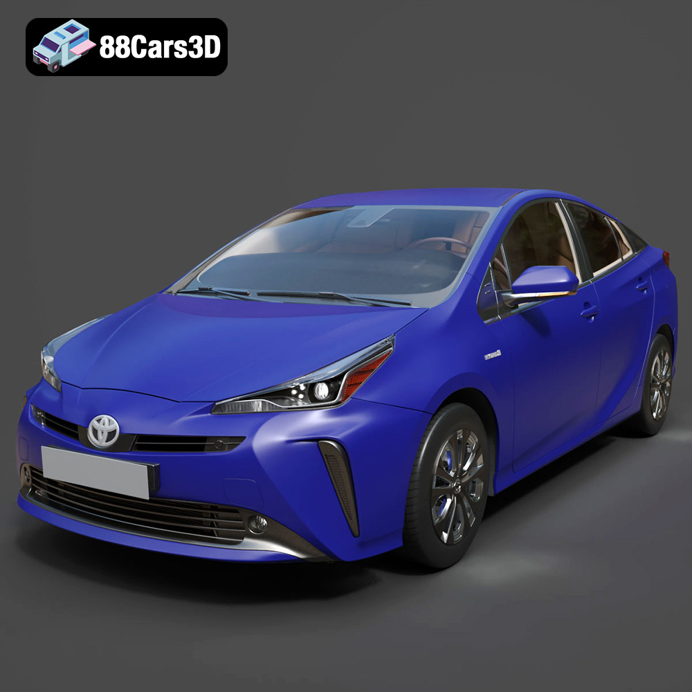
Texture: Yes | Material: Yes
Download the highly detailed, game-ready Toyota Prius 2019 3D Model. Features aerodynamic hybrid styling, precise exterior detailing, and modern interior cockpit. Includes .blend, .fbx, .obj, .glb, .stl, .ply, .unreal, and .max formats for game development, AR/VR, and rendering.
Price: $220.50
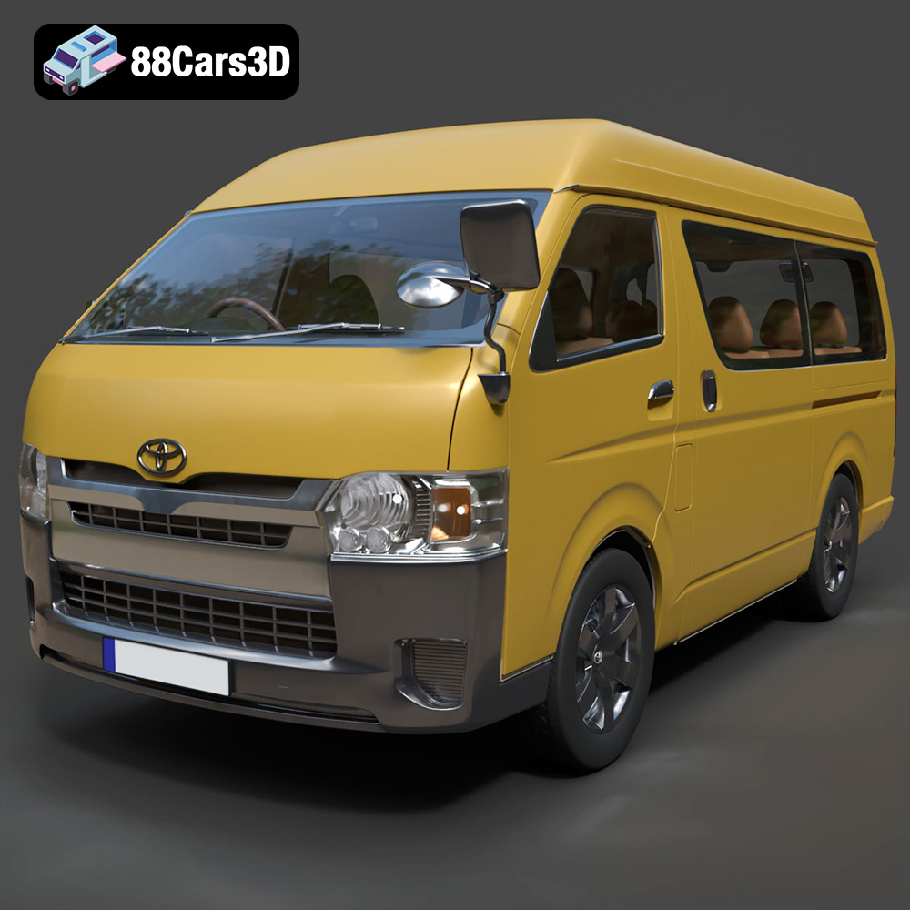
Texture: Yes | Material: Yes
Download the highly detailed, game-ready Toyota Hiace Passenger Van L1H3 DX 2013 3D Model. Features authentic high-roof van body proportions, detailed interior seating layout, and realistic exterior lighting. Includes .blend, .fbx, .obj, .glb, .stl, .ply, .unreal, and .max formats for game development, AR/VR, and rendering.
Price: $208.99
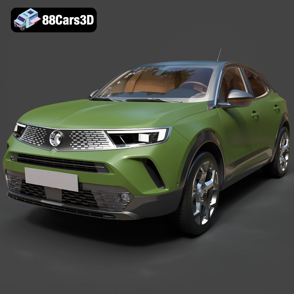
Texture: Yes | Material: Yes
Download the highly detailed, game-ready Vauxhall Mokka 2021 3D Model. Features signature Vizor front grille, sharp LED lighting, and modern digital interior elements. Includes .blend, .fbx, .obj, .glb, .stl, .ply, .unreal, and .max formats for game development, AR/VR, and rendering.
Price: $226.00
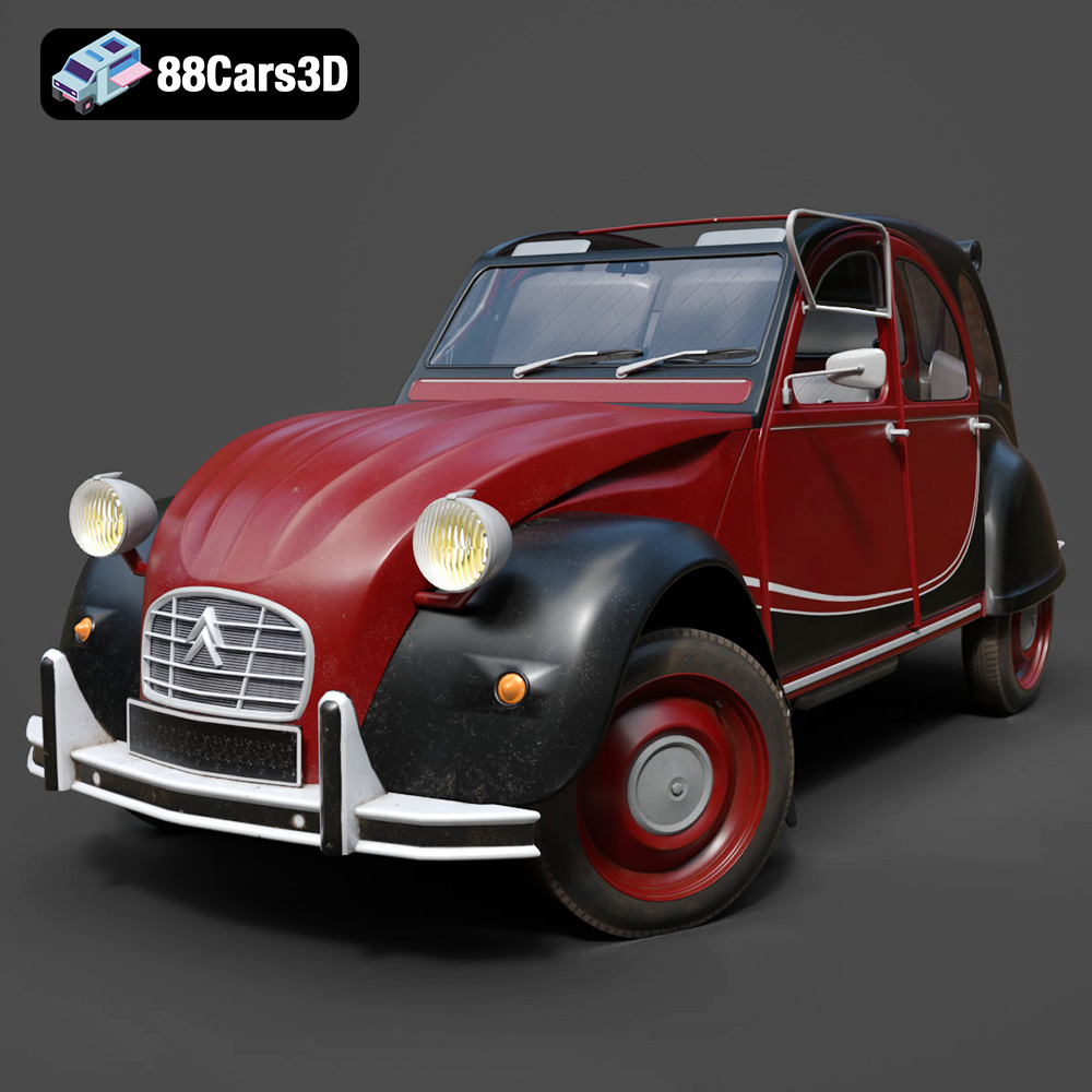
Texture: Yes | Material: Yes
Download the highly detailed, game-ready Citroën 2CV Charleston 1986 3D Model. Features two-tone retro livery, classic rounded wings, and signature canvas soft-top roof. Includes .blend, .fbx, .obj, .glb, .stl, .ply, .unreal, and .max formats for game development, AR/VR, and rendering.
Price: $99.99
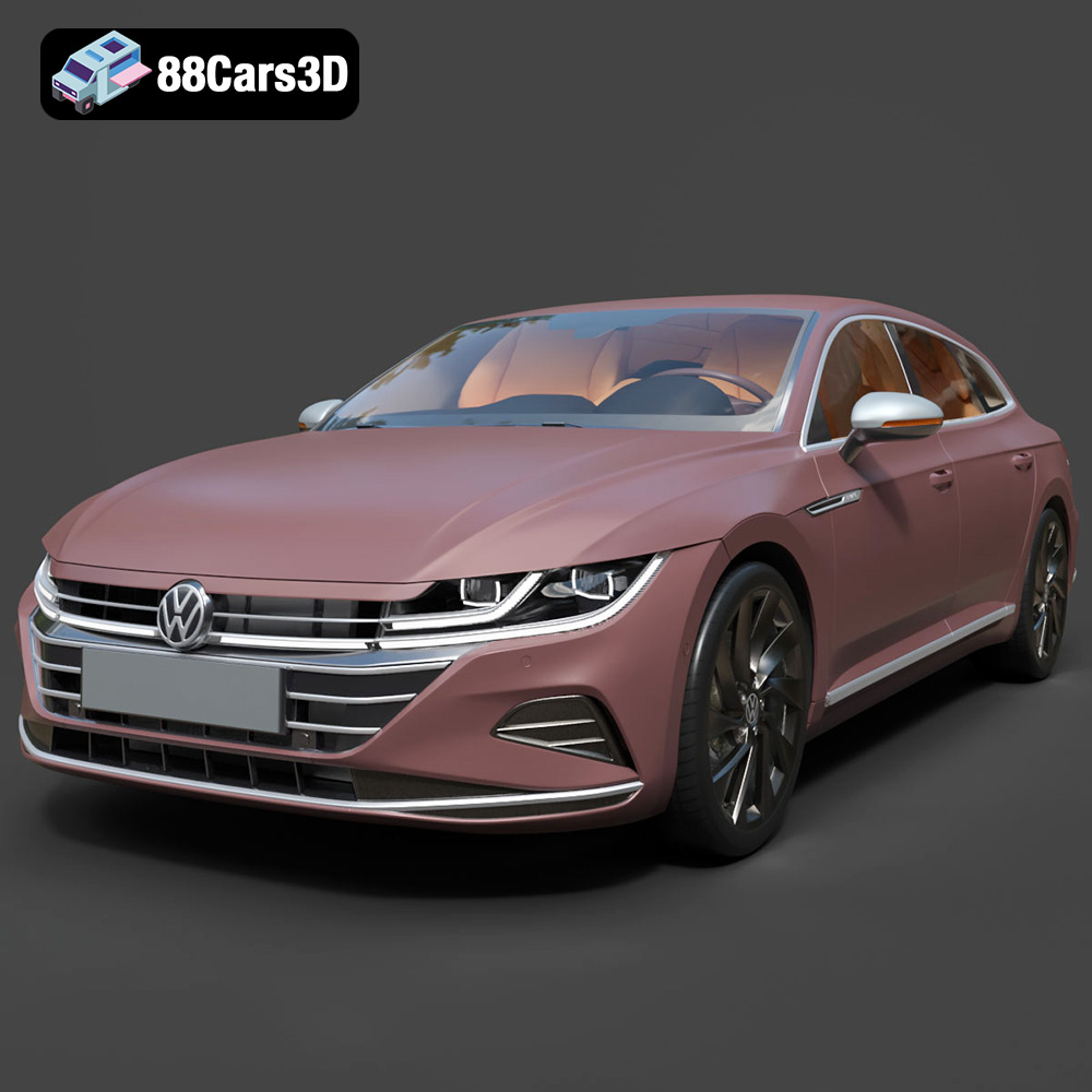
Texture: Yes | Material: Yes
Download the highly detailed, game-ready Volkswagen Arteon Shooting Brake Elegance 2021 3D Model. Features sleek wagon proportions, detailed LED headlights, and modern interior styling. Includes .blend, .fbx, .obj, .glb, .stl, .ply, .unreal, and .max formats for game development, AR/VR, and rendering.
Price: $225.50
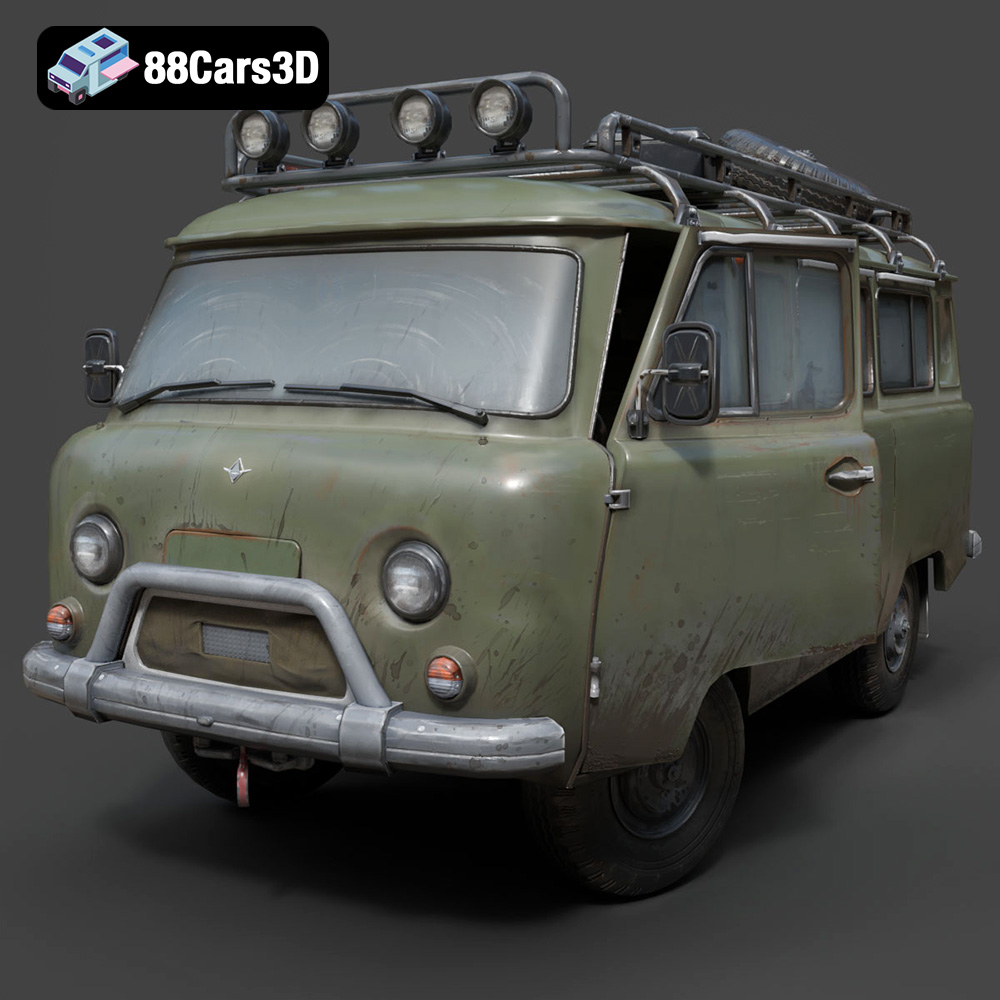
Texture: Yes | Material: Yes
Download the highly detailed, game-ready Soviet Vehicle Bukhanka 3D Model. Features iconic cab-over design, rugged utility styling, and detailed undercarriage. Includes .blend, .fbx, .obj, .glb, .stl, .ply, .unreal, and .max formats for game development, AR/VR, and rendering.
Price: $99.99
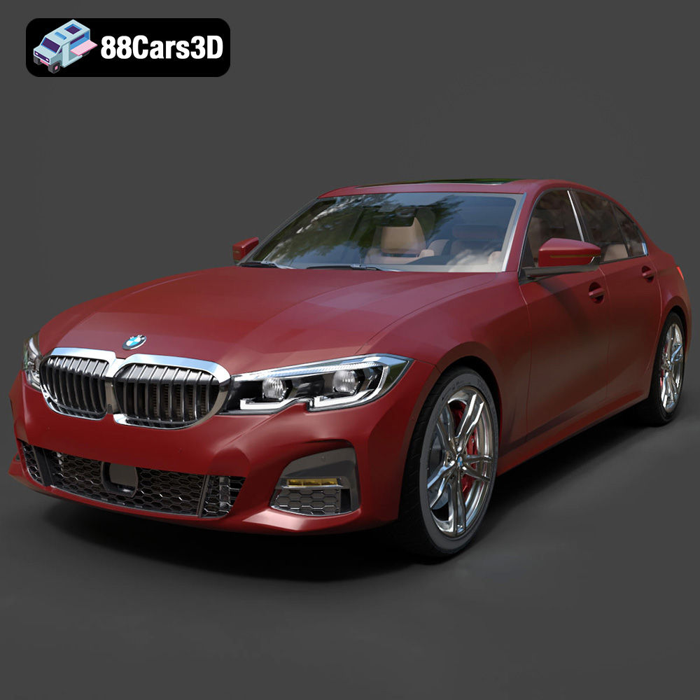
Texture: Yes | Material: Yes
Download the highly detailed, game-ready BMW 3er VII (G2x) 3D Model. Features iconic kidney grille geometry, detailed LED lighting, and precise interior cockpits. Includes .blend, .fbx, .obj, .glb, .stl, .ply, .unreal, and .max formats for game development, AR/VR, and rendering.
Price: $299.50
Texture: Yes | Material: Yes
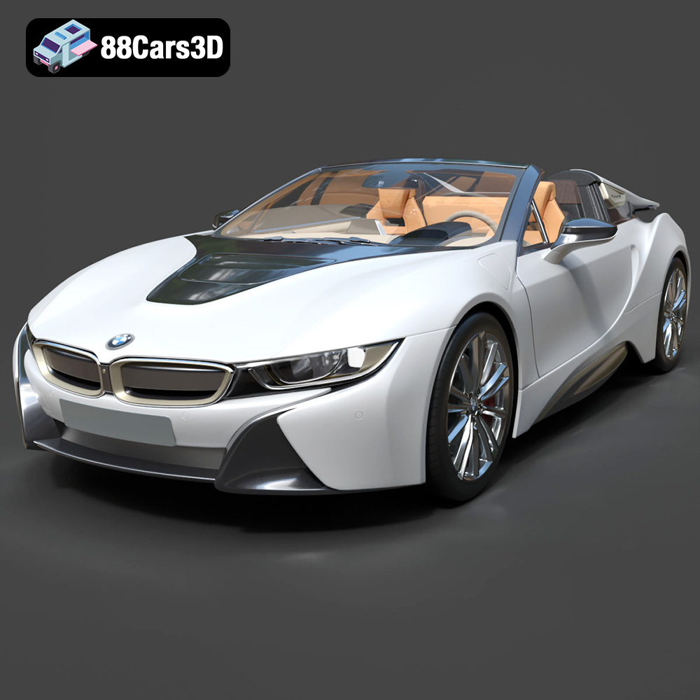
Download the highly detailed, game-ready BMW i8 Roadster 2019 3D Model. Features iconic butterfly doors, futuristic aerodynamic styling, and detailed hybrid sports car aesthetics. Includes .blend, .fbx, .obj, .glb, .stl, .ply, .unreal, and .max formats for game development, AR/VR, and rendering.
Price: $171.00
Texture: Yes | Material: Yes
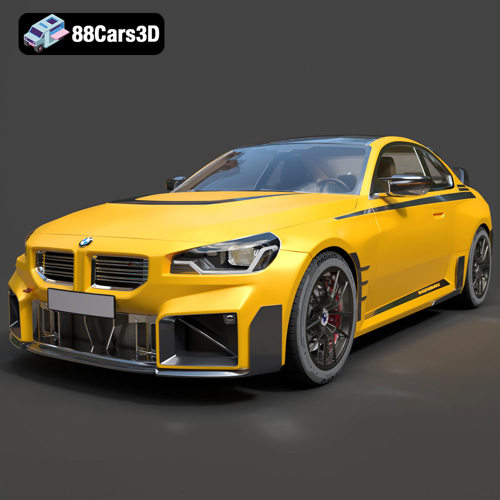
Download the highly detailed, game-ready BMW M2 M Performance 3D Model. Features aggressive M Performance aero parts, detailed interior, and signature front grille. Includes .blend, .fbx, .obj, .glb, .stl, .ply, .unreal, and .max formats for game development, AR/VR, and rendering.
Price: $299.50
Texture: Yes | Material: Yes
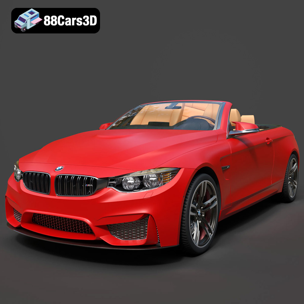
Download the highly detailed, game-ready BMW M4 F33 Convertible 2015 3D Model. Features aggressive M body styling, quad exhaust setup, and detailed M sport interior. Includes .blend, .fbx, .obj, .glb, .stl, .ply, .unreal, and .max formats for game development, AR/VR, and rendering.
Price: $225.99
