
Real-time automotive visualization has evolved from simple shaded previews to photorealistic, cinematic-grade rendering. With Unreal Engine leading the charge in virtual production, real-time car configurators, and architectural rendering, understanding the intricacies of Physically-Based Rendering (PBR) materials is crucial. Creating photorealistic vehicle surfaces requires more than applying basic textures; it demands an in-depth understanding of light transport, dual-specular lobes, anisotropic reflections, micro-detail blending, and shader graph optimization.
In this technical guide, we will explore advanced PBR workflows in Unreal Engine’s Material Editor specifically tailored for high-end automotive rendering. You will learn how to construct multi-layered metallic car paint with procedural flakes, author anisotropic carbon fiber, set up realistic glass and interior shaders, and structure modular material graphs optimized for real-time performance. Whether you are building real-time configurators, rendering cinematic shots, or developing interactive game environments, mastering these workflows will elevate the fidelity of your automotive assets.
—
Physically-Based Rendering relies on strict energy conservation principles: the total amount of light reflected by a surface cannot exceed the total light received. When building automotive materials in Unreal Engine, understanding how inputs like Base Color, Metallic, Roughness, and Specular interact is essential for maintaining physical accuracy across varying lighting environments.
Automotive surfaces consist of dielectric materials (paint clear coats, glass, plastics, leather) and metallic materials (bare aluminum, chrome, carbon trim accents). Managing these surface types requires a precise approach to channel data:
Specular = ((IOR - 1) / (IOR + 1))^2 / 0.08.The Fresnel effect dictates that reflection strength increases as the viewing angle approaches grazing angles (90 degrees relative to the surface normal). Unreal Engine calculates Fresnel automatically using Schlick’s approximation within its shading models. However, when building custom material functions or multi-layer shaders, preserving the relationship between specular reflection and diffuse absorption is critical.
When light hits a vehicle’s bodywork, a portion reflects off the surface boundary immediately, while the remainder penetrates into the substrate, undergoes subsurface scattering, and emerges as diffuse color. High surface reflections must naturally darken the underlying diffuse contribution to preserve energy conservation. You can study official workflow guidelines directly on the Unreal Engine Learning Hub to ensure your shader networks align with native engine rendering pipelines.
Standard assets rely on the Default Lit shading model, which provides a single specular lobe. However, automotive body panels consist of distinct structural layers: a primer, a pigment/flake base layer, and a top protective polyurethane clear coat.
To accurately render car paint, set the material’s Shading Model to Clear Coat. This model introduces two independent specular lobes:
To use independent normals for both layers, navigate to Project Settings > Engine > Rendering > Materials and enable Clear Coat Enable Second Normal. This allows high-frequency micro-detail (such as metallic flakes) on the base layer while preserving a smooth, glossy clear coat reflection on top.
—
Achieving realistic car paint and composite materials requires custom shader logic within the Unreal Engine Material Editor. Below, we break down the workflows for creating multi-layered metallic car paint and anisotropic carbon fiber.
Realistic metallic car paint requires three core visual phenomena: deep base color tint, specular metallic flake sparkle, and subtle surface imperfection (“orange peel”) in the clear coat surface layer.
Car Paint Layer Structure:
To simulate metallic flakes, high-frequency tiling normal maps or procedural noise algorithms are blended into the Clear Coat Bottom Normal input pin. To prevent visual noise and moiré patterns at distance, implement camera-distance fading using the CameraDepthFade or PixelDepth node:
// Pseudocode representation of Flake Normal Intensity Distance Fade
float Distance = Clamp((PixelDepth - FadeStart) / (FadeEnd - FadeStart), 0.0, 1.0);
float3 FinalFlakeNormal = Lerp(DetailedFlakeNormal, FlatNormal, Distance);
The clear coat “orange peel” effect is achieved by applying a subtle, large-scale Noise or Normal map directly to the primary Normal pin of the material while assigning the high-frequency flake normal to the Clear Coat Bottom Normal pin. This results in broad, organic reflection distortion on the outer layer while keeping the internal metallic flakes sharp.
Carbon fiber consists of woven strands of carbon filaments encased in resin. Because these woven fibers reflect light directional across their weave pattern, standard isotropic specular reflections look flat and incorrect. We must leverage Unreal Engine’s Anisotropy inputs.
0.0 (resin layer is dielectric) or 0.1 for specialized carbon coatings.-0.8 and 0.8) to the Anisotropy input pin to elongate specular highlights perpendicular to the weave direction.CustomRotator node linked to the UV space) to drive the vector direction of the anisotropic highlight along the 2D weave axes.When sourcing professional 3D car models from platforms like 88cars3d.com, the mesh geometry includes precise UV mapping, allowing anisotropic tangent vectors to follow the natural contour and weave directions of carbon fiber body components cleanly without seam distortion.
Certain high-end paints—such as “Candy Apple Red”—utilize clear coats infused with subtle dyes. In these paints, light traveling through the clear coat layer absorbs specific light wavelengths before reflecting off the base layer.
In Unreal Engine, this effect is recreated by modulating the Base Color dynamically using a Fresnel node as an interpolation alpha. At grazing angles, light travels through a thicker optical path of tinted resin, shifting the overall color output to a darker, more saturated hue. For complex pearl paints, dual-tone lerps controlled by a custom Fresnel exponent create smooth color shifts across curved body panels.
—
Vehicles feature diverse material types beyond body paint. Real-time automotive visualizers must handle refractive automotive glass, multi-element headlight enclosures, and mixed-fabric interior materials.
Unreal Engine offers two primary approaches for glass materials: Translucent and Thin Translucent.
| Feature | Standard Translucent | Thin Translucent |
|---|---|---|
| Best For | Thick glass blocks, solid objects | Thin automotive windshields, side windows |
| Lighting Support | Requires Forward Shading / Volumetric Translucency | Full physically-based light response natively |
| Refraction | Offset-based Index of Refraction (IOR) | Physically accurately scaled thin-shell refraction |
| Color Tinting | Modulated Opacity & Base Color | Driven via Transmission Color pin |
For modern real-time visualization, the Thin Translucent shading model is recommended for vehicle glass. Set the material’s Blend Mode to Thin Translucent, connect a specular tint color to the Transmission Color pin, and use a scalar value of 1.52 (the IOR of real-world glass) linked to the Refraction input pin.
To simulate subtle window tinting or heating grid lines, use secondary UV channels to tile detail masks across the opacity channel while maintaining clean reflections on the outer glass surface.
Modern headlights are complex optical assemblies consisting of outer plastic lenses, interior projector bulbs, LED light pipes, and parabolic chrome reflectors. Recreating these requires a structured material setup:
Vehicle interiors feature varied material textures, ranging from smooth leather to matte synthetic micro-fibers like Alcantara.
To author convincing Alcantara, standard PBR roughness maps are insufficient because micro-fibers scatter light across grazing angles. To achieve this look, use the Cloth shading model or construct a custom material graph incorporating the FuzzyShading Material Function. Set the Subsurface Color to a slightly lighter variant of the Base Color map to mimic micro-fiber rim lighting.
For perforated leather seats, use a BlendAngleCorrectedNormals node to blend high-resolution leather grain textures with a tileable perforation normal map, masking the perforation holes with zero specular output and high roughness values.
—
To keep complex vehicle assets manageable and efficient, avoid building monolithic shaders for individual meshes. Instead, adopt a modular, function-driven master material pipeline.
A master automotive material architecture relies on clean, reusable Material Functions (MF). These encapsulate recurring logic—such as flake generation, detail normal blending, or Fresnel color shifting—into single reusable nodes.
For example, a standardized MF_CarPaint_Flakes function can take inputs for Tiling Frequency, Flake Intensity, and Depth Fade Distance, outputting optimized Base Color adjustments and Clear Coat Bottom Normal maps across every vehicle asset in your project.
When working on dynamic vehicle configurators, artists and developers must interact with materials using Material Instances rather than editing master material graphs directly. Organize master material parameters logically using the Group attribute within node properties:
01 - Car Paint Setup (Base Color, Metallic, Specular, Roughness)02 - Clear Coat Controls (Clear Coat Coverage, Clear Coat Roughness, Orange Peel Normal Strength)03 - Flake Properties (Flake Color, Flake Scale, Flake Normal Intensity, Depth Blur)04 - Imperfections & Dirt (Dust Mask Tiling, Fingerprint Roughness Offset, Dirt Normal Blend)Pre-configured asset libraries sourced from marketplaces such as 88cars3d.com feature organized, logically grouped material slots and clean UV mapping out of the box. This modular design simplifies linking parameters directly to Unreal Engine Blueprints for runtime real-time material swapping.
Unreal Engine supports Material Layers and Material Layer Blends, allowing you to stack complete material definitions (such as clean car paint, mud, rust, and carbon fiber trim) using stackable layer stacks rather than duplicating complex math within a single material graph.
Using the Set Material Layer Parameter Values node in Blueprint, artists can adjust dirt accumulation levels or swap individual vehicle trim panels on the fly without triggering expensive shader re-compilations at runtime.
—
High visual fidelity must be balanced with real-time performance. Rendering complex material stacks at target frame rates (e.g., 60 FPS at 4K resolution) requires disciplined optimization of texture budgets, instruction counts, and engine rendering pipelines.
To minimize memory bandwidth consumption and reduce Draw Calls, pack single-channel grayscale maps into unified multi-channel RGBA textures, commonly known as ARM Maps (Ambient Occlusion, Roughness, Metallic):
Ensure packed maps use the Masks (no sRGB) compression setting within Unreal Engine’s Texture Properties to prevent gamma curve distortions on scalar data channels.
| Texture Type | Compression Setting | Target Resolution (Hero Vehicle) |
|---|---|---|
| Base Color / Tint | DXT1 / BC1 (sRGB Enabled) | 4096 x 4096 |
| Normal Map | DXT5 / BC5 (Normalmap) | 4096 x 4096 |
| Packed ARM Map | Masks (No sRGB / VectorDisplacement) | 2048 x 2048 |
| Detail Normals / Flakes | DXT5 / BC5 (Normalmap) | 1048 x 1048 (High Tiling) |
Keep pixel shader instruction counts manageable by reducing mathematical complexity inside master materials. In the Material Editor viewport, select View Mode > Shader Complexity (or press Alt + 8) to evaluate performance costs visually across your model surfaces.
Static Switch Parameters. These evaluate at compile time, eliminating unnecessary instruction branches for material instances that do not require those features.Unreal Engine 5 introduced Nanite Virtualized Geometry and Lumen Global Illumination and Reflections, altering how materials interact with rendering engines:
Nanite Geometry Compatibility: As of Unreal Engine 5.1+, Nanite supports Masked materials and dual-side rendering, as well as Programmable Rasterization for opacity maps. However, fully transparent/translucent materials (such as vehicle glass) still require standard non-Nanite pipeline fallbacks or hybrid mesh configurations. When importing models from 88cars3d.com, vehicle meshes are split logically by material type, enabling you to apply Nanite to high-poly chassis and engine components while keeping glass windows on traditional rendering passes.
Lumen Reflections and Hardware Ray Tracing: Clear coat paints rely heavily on accurate environment reflections. To optimize Lumen for dual-layer automotive shaders:
—
Follow this step-by-step assembly process to construct a production-ready, optimized metallic car paint master material in Unreal Engine:
M_CarPaint_Master. Set the Shading Model to Clear Coat in the Details panel.Vector Parameter named Base Color. Multiply this parameter by a subtle color variation driven by a Fresnel node to simulate pigment shift across oblique angles.Scalar Parameter named ClearCoat_Strength (default = 1.0) and connect it to the Clear Coat input pin. Create a second scalar named ClearCoat_Roughness (default = 0.02) and connect it to Clear Coat Roughness.Texture Coordinate node multiplied by a Scalar Parameter named Flake_Tiling. Multiply the normal map’s XY channels by a Scalar Parameter named Flake_Bump_Strength. Connect the result to the Clear Coat Bottom Normal input pin.Scalar Parameter named OrangePeel_Intensity. Connect this normal tree directly to the primary Normal input pin.M_CarPaint_Master and select Create Material Instance. Assign the instance to your target vehicle model and fine-tune parameters in real time using the viewport preview.—
Mastering advanced PBR workflows in Unreal Engine’s Material Editor requires a balance between real-world physics and real-time graphics optimization. By utilizing dual-layer Clear Coat shading models, implementing physical anisotropic reflections for carbon fiber, constructing clean Thin Translucent glass networks, and organizing modular shader graphs with optimized ARM texture packing, you can achieve photorealistic automotive visuals smoothly in real time.
Whether you are building dynamic interactive car configurators, rendering virtual production scenes on LED walls, or creating immersive real-time gaming environments, having clean 3D assets mapped with organized material IDs is critical to a fast rendering pipeline. Explore the production-ready catalog at 88cars3d.com to source high-poly, impeccably textured 3D car models optimized for seamless integration with Unreal Engine’s advanced material workflows.
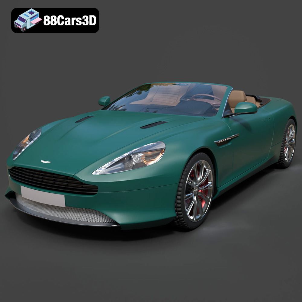
Texture: Yes | Material: Yes
Download the highly detailed, game-ready Aston Martin Virage Volante 2012 3D Model. Features sleek open-top GT design, iconic front grille, and detailed luxury interior trim. Includes .blend, .fbx, .obj, .glb, .stl, .ply, .unreal, and .max formats for game development, AR/VR, and rendering.
Price: $9
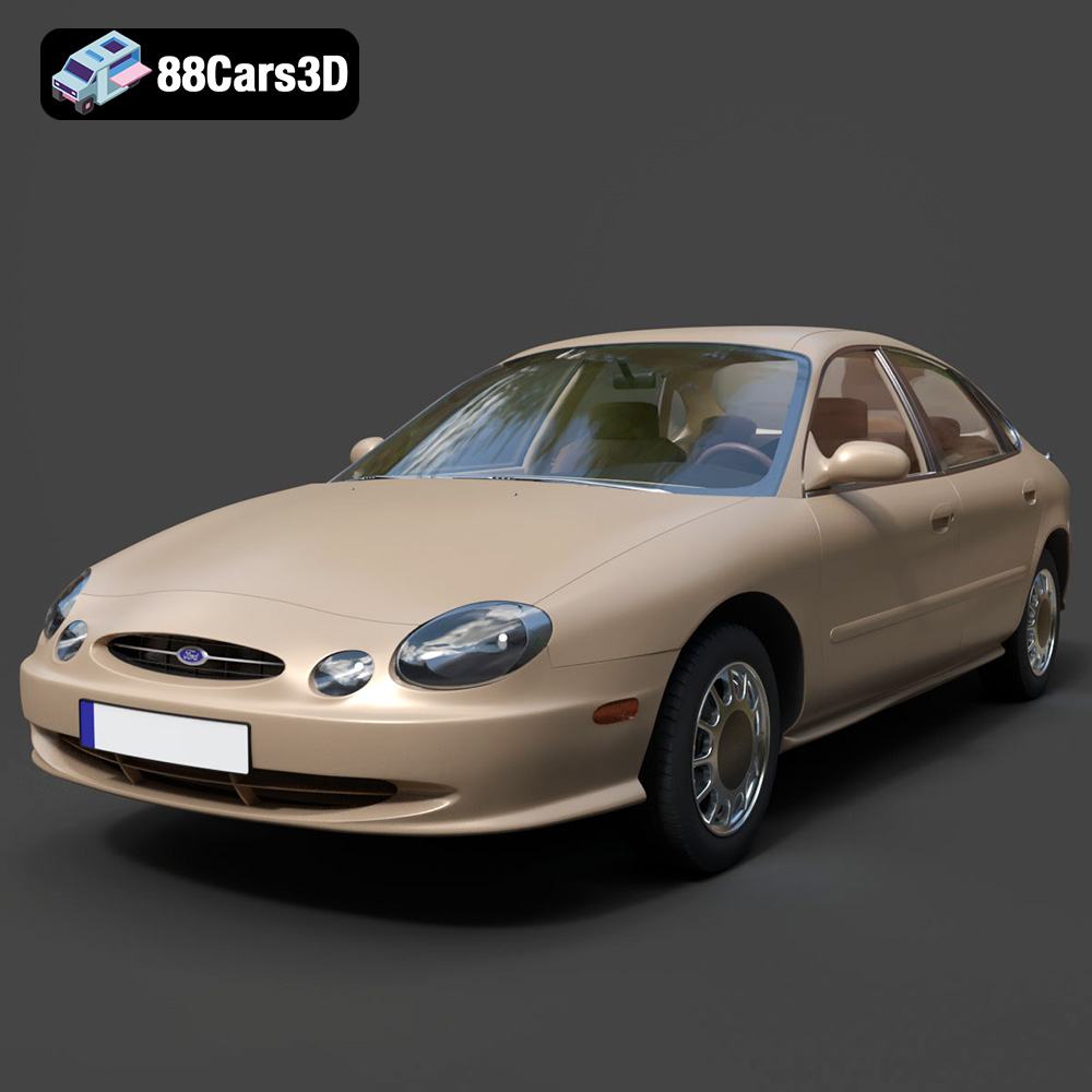
Texture: Yes | Material: Yes
Download the highly detailed, game-ready Ford Taurus 1996 3D Model. Features revolutionary oval exterior styling, detailed interior, and accurate chassis geometry. Includes .blend, .fbx, .obj, .glb, .stl, .ply, .unreal, and .max formats for game development, AR/VR, and rendering.
Price: $9
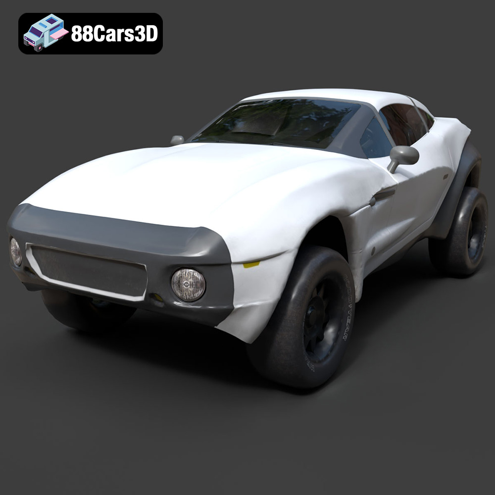
Texture: Yes | Material: Yes
Download the highly detailed, game-ready Local Motors Rally Fighter 3D Model. Features aggressive off-road long-travel suspension, detailed interior cockpit, and high-clearance body styling. Includes .blend, .fbx, .obj, .glb, .stl, .ply, .unreal, and .max formats for game development, AR/VR, and rendering.
Price: $99.99
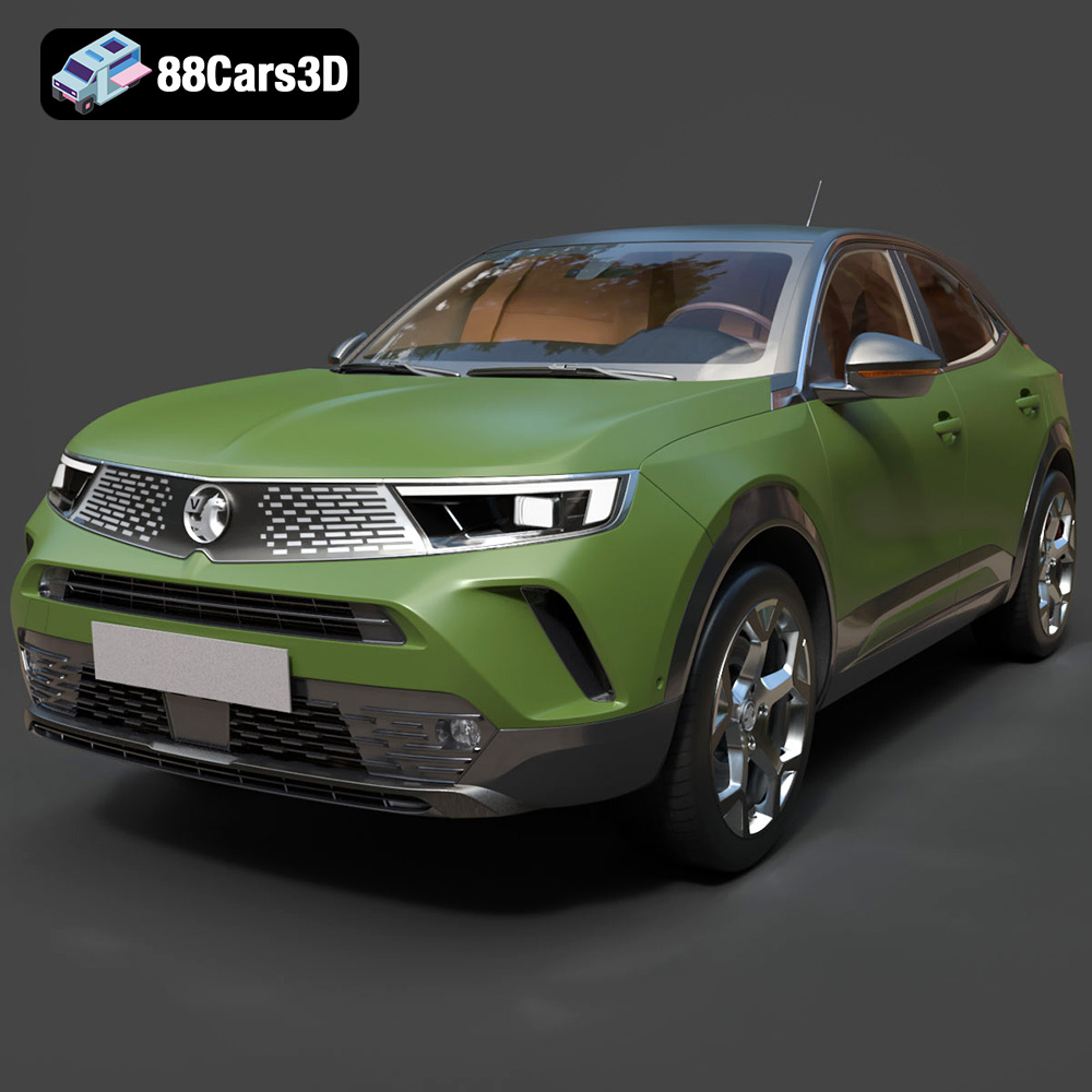
Texture: Yes | Material: Yes
Download the highly detailed, game-ready Vauxhall Mokka 2021 3D Model. Features signature Vizor front grille, sharp LED lighting, and modern digital interior elements. Includes .blend, .fbx, .obj, .glb, .stl, .ply, .unreal, and .max formats for game development, AR/VR, and rendering.
Price: $9
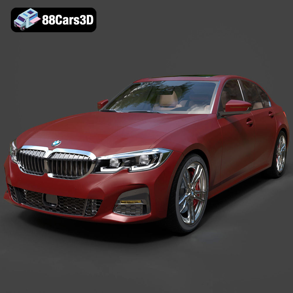
Texture: Yes | Material: Yes
Download the highly detailed, game-ready BMW 3er VII (G2x) 3D Model. Features iconic kidney grille geometry, detailed LED lighting, and precise interior cockpits. Includes .blend, .fbx, .obj, .glb, .stl, .ply, .unreal, and .max formats for game development, AR/VR, and rendering.
Price: $9
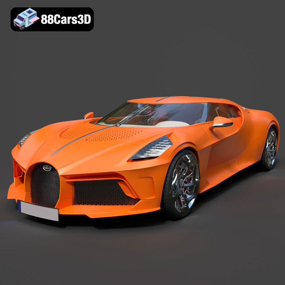
Texture: Yes | Material: Yes
Download the highly detailed, game-ready Bugatti La Voiture Noire 2019 3D Model. Features seamless jet-black carbon bodywork, distinctive six-tailpipe exhaust, and continuous LED light strip. Includes .blend, .fbx, .obj, .glb, .stl, .ply, .unreal, and .max formats for game development, AR/VR, and rendering.
Price: $9
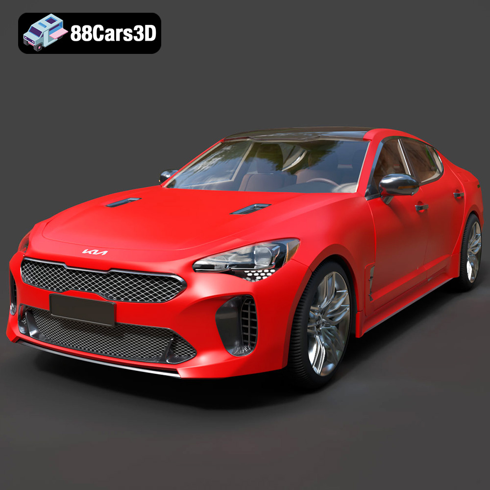
Texture: Yes | Material: Yes
Download the highly detailed, game-ready Kia Stinger 2021 3D Model. Features tiger-nose grille styling, quad exhaust tips, and high-fidelity interior details. Includes .blend, .fbx, .obj, .glb, .stl, .ply, .unreal, and .max formats for game development, AR/VR, and rendering.
Price: $9
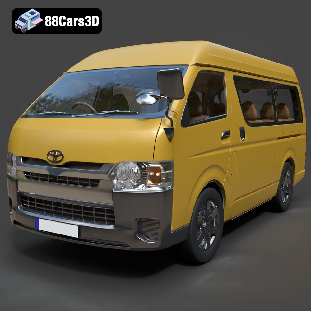
Texture: Yes | Material: Yes
Download the highly detailed, game-ready Toyota Hiace Passenger Van L1H3 DX 2013 3D Model. Features authentic high-roof van body proportions, detailed interior seating layout, and realistic exterior lighting. Includes .blend, .fbx, .obj, .glb, .stl, .ply, .unreal, and .max formats for game development, AR/VR, and rendering.
Price: $9
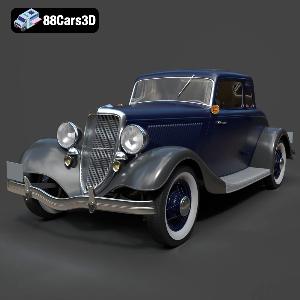
Texture: Yes | Material: Yes
Download the highly detailed, game-ready Ford Coupe 1934 3D Model. Features sweeping fenders, iconic 1930s grille design, and authentic vintage proportions. Includes .blend, .fbx, .obj, .glb, .stl, .ply, .unreal, and .max formats for game development, AR/VR, and rendering.
Price: $9
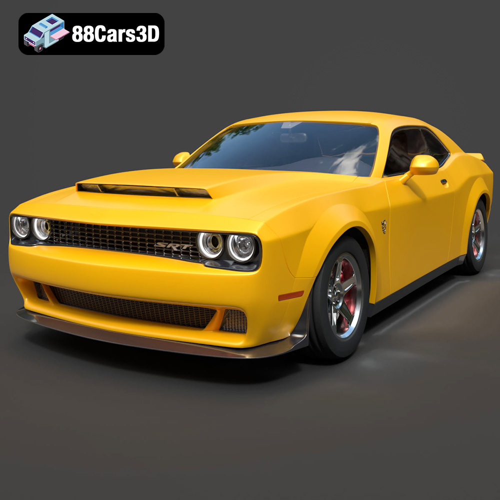
Texture: Yes | Material: Yes
Download the highly detailed, game-ready Dodge Demon SRT 3D Model. Features aggressive widebody styling, supercharged HEMI V8 details, and high-fidelity exterior details. Includes .blend, .fbx, .obj, .glb, .stl, .ply, .unreal, and .max formats for game development, AR/VR, and rendering.
Price: $9
